
MM33X1BLK - Flat screen mount Middle Atlantic - Free user manual and instructions
Find the device manual for free MM33X1BLK Middle Atlantic in PDF.
User questions about MM33X1BLK Middle Atlantic
0 question about this device. Answer the ones you know or ask your own.
Ask a new question about this device
Download the instructions for your Flat screen mount in PDF format for free! Find your manual MM33X1BLK - Middle Atlantic and take your electronic device back in hand. On this page are published all the documents necessary for the use of your device. MM33X1BLK by Middle Atlantic.
USER MANUAL MM33X1BLK Middle Atlantic
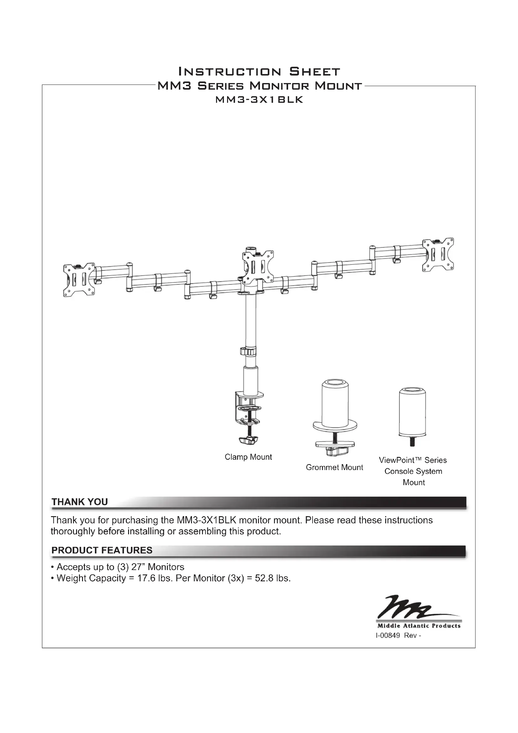
THANK YOU
Thank you for purchasing the MM3-3X1BLK monitor mount. Please read these instructions thoroughly before installing or assembling this product.
PRODUCT FEATURES
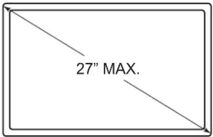
- Accepts up to (3) 27" Monitors
- Weight Capacity = 17.6 lbs. Per Monitor (3x) = 52.8 lbs.
IMPORTANT SAFETY INSTRUCTIONS
- Read these instructions.
- Heed all warnings.
- Clean only with dry cloth.
- Keep these instructions.
- Follow all instructions.
- Only use attachments/accessories specified by the manufacturer.

DANGER HAZARDOUS VOLTAGE: The lightning flash with the arrowhead symbol, within an equilateral triangle is intended to alert the user to the presence of uninsulated dangerous voltage within the product's enclosure that may be of sufficient magnitude to constitute a risk of electric shock to persons.

WARNING: A warning alerts you to a situation that could result in serious personal injury or death.

CAUTION: A caution alerts you to a situation that may result in minor personal injury or damage to the product and/or property.
NOTE: A note is used to highlight procedures pertaining to the installation, operation, or maintenance of the product.

WARNING: Failure to read, understand and follow the following information can result in serious personal injury, damage to the equipment or voiding of the warranty. It is the responsibility of the Installer/User to ensure that this product is loaded according to specifications.

WARNING: Exceeding the weight capacity may result in personal injury or equipment damage. The combined weight of all components attached to the mount must not exceed weights listed on page 3.

WARNING: Death or serious injury may occur when children climb on audio and/or video equipment furniture. A remote control or toys placed on the furnishing may encourage a child to climb on the furnishing and as a result the furnishing may tip over on the child.

WARNING: Relocating audio and/or video equipment to furniture not specifically designed to support audio and/or video equipment may result in death or serious injury due to the furnishing collapsing or over turning onto a child.

WARNING: Be aware of pinch points and do not place fingers in between moving parts.

WARNING: Use this product for its intended use and only use attachments recommended by the manufacturer.

WARNING: Do not use a damaged product. Return damaged products to a qualified service center for repair.

WARNING: Not intended for outdoor use.
INSTRUCTIONS IMPORTANTES SUR LA SÉCURITÉ
- Lire ces instructions.
| Model Weight Rating | |
| MM3-3X1BLK 17.6 lbs. Per Monitor | (3x) = 52.8 lbs. |
SUPPLIED COMPONENTS AND HARDWARE
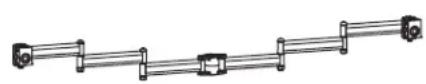
Arm Assembly A

Pole B
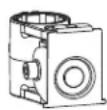
Monitor Mount
Knuckle
C
(3x)
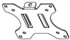
Display Mount
Bracket
D

Adapter Plate
E
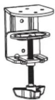
Clamp
Assembly
F

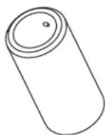
Cup Mount Plate G
Pole
Base
H

(3x)
Plate
Screw
J

(6x)
Arm Cable Clip
(K)
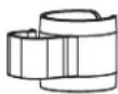
Cable Management
Clip
L

Grommet
Plate
M

(4x)
Flat Head
Screw
N

Short Carriage Bolt P

Long
Carriage
Bolt
R

(5x)
Adhesive Pad
S

Knob
T
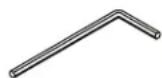
6mm Hex Key
U
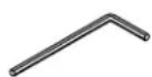
5mm Hex Key
V
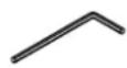
4mm Hex Key
W
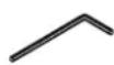
3mm Hex Key
X
MONITOR HARDWARE

(12x)
M4x12 Pan
Head Screw
M-A

(12x)
M4x16 Pan
Head Screw
M-B

(12x)
M5x12 Pan
Head Screw
M-C

(12x)
M5x16 Pan
Head Screw
M-D

(12x)
Washer
M-E

(12x)
Spacer
M-F
NOTE: Additional hardware is included that may not be required for your installation.
REQUIRED TOOLS
• #2 Phillips Head Screwdriver
• #4 Slotted Screwdriver
- Standard Socket Set
- 5/16" Socket

WARNING: Use tools with caution and follow all necessary safety protocols.
- Insert carriage bolt (R) through adapter plate (E) as shown. (FIGURE A)
- Attach adapter plate (E) to pole base (H) using (4x) flat head screws (N) and tighten using 4mm hex key (W) as shown.
- Apply (4x) adhesive pads (S) around the bottom of adapter plate (E) evenly spaced.
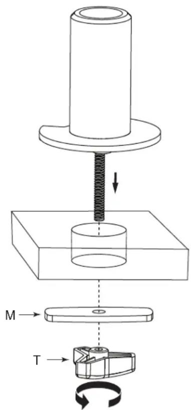
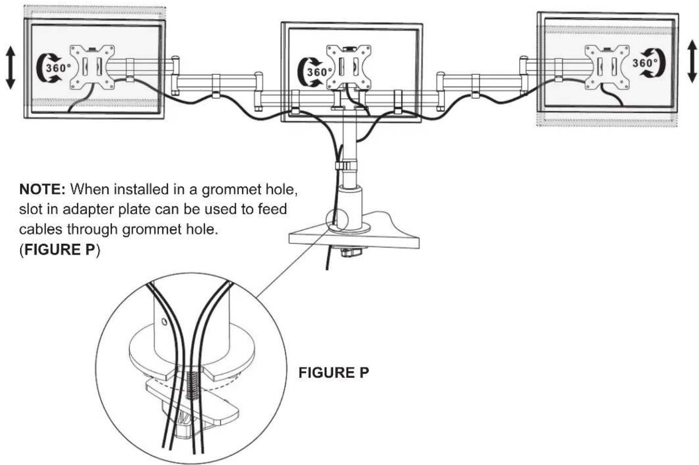
- Insert pole base assembly into grommet hole in work surface. Use grommet plate (M) and knob (T), to tighten base securely to work surface.
NOTE: If using grommet hole for wire management, position assembly with cutout in line with wires before tightening assembly in place.
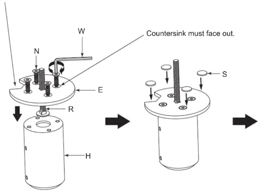
FIGURE A
MOUNTING THE BASE (CONTINUED)
CLAMP MOUNTING
- Attach pole base (H) to clamp assembly (F) using (4x) flat head screws (N) and tighten using 4mm hex key (W) as shown. (FIGURE B)
- Apply (4x) adhesive pads (S) around the bottom of clamp assembly (F) evenly spaced.
- Slide assembly over work surface and tighten securely in place.
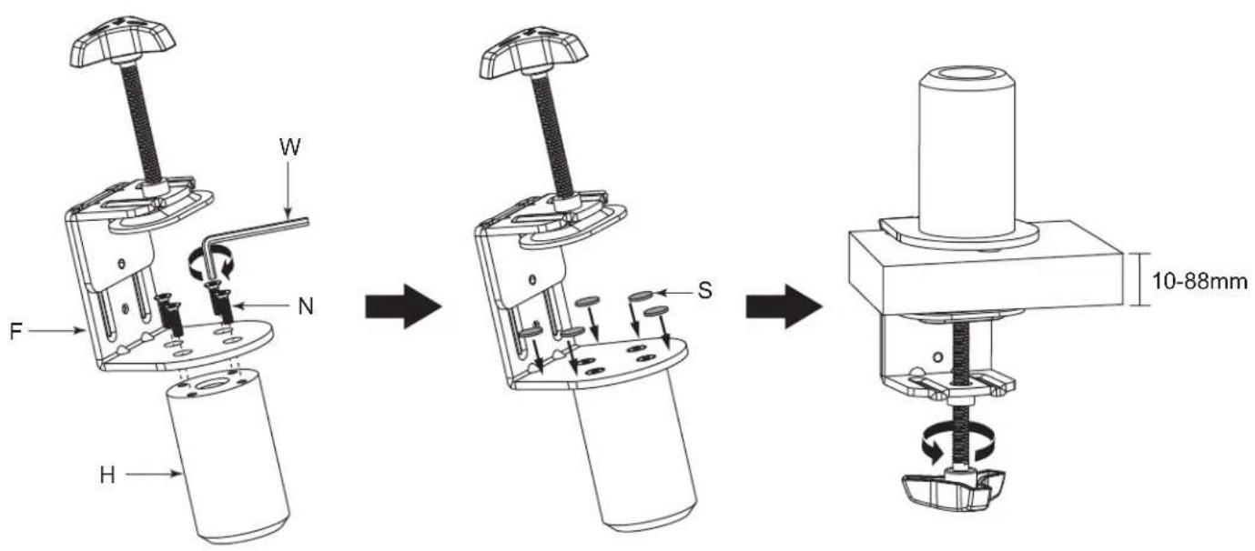
FIGURE B
MOUNTING THE BASE (CONTINUED)
VIEWPOINT CONSOLE MOUNTING
- Insert short carriage bolt (P) into cup mount plate (G) as shown. (FIGURE C)
- Attach cup mount plate (G) to pole base (H) using (4x) flat head screws (N) and tighten using 4mm hex key (W) as shown.
- Apply (4x) adhesive pads (S) over each screw head.
- Select the mount location along the back of the ViewPoint console frame and remove protective dustcap nearest to your desired mount position. Thread the base assembly into frame tightening base down securely. (FIGURE C)
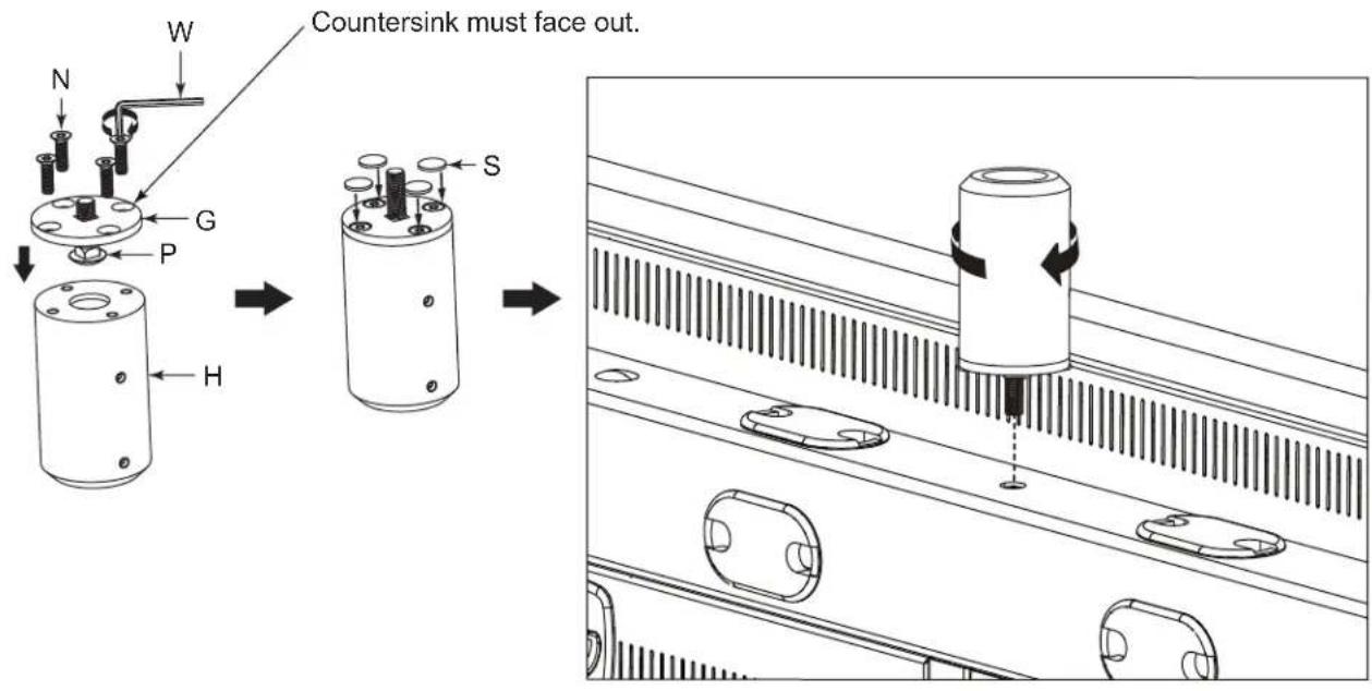
FIGURE C
ASSEMBLING POLE TO BASE
- Slide cable management clip (L) onto pole (B) as shown. (FIGURE D)
- Loosen set screws in pole base (H) and push onto pole (B) until it bottoms out.
- Using 3mm hex key (X), tighten set screws to lock pole onto base.
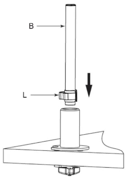

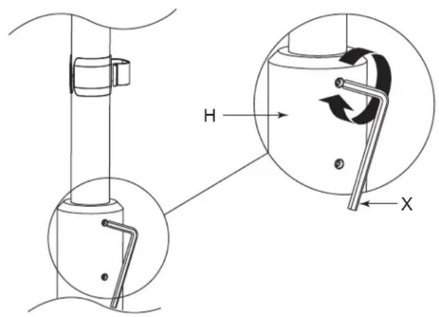
FIGURE D
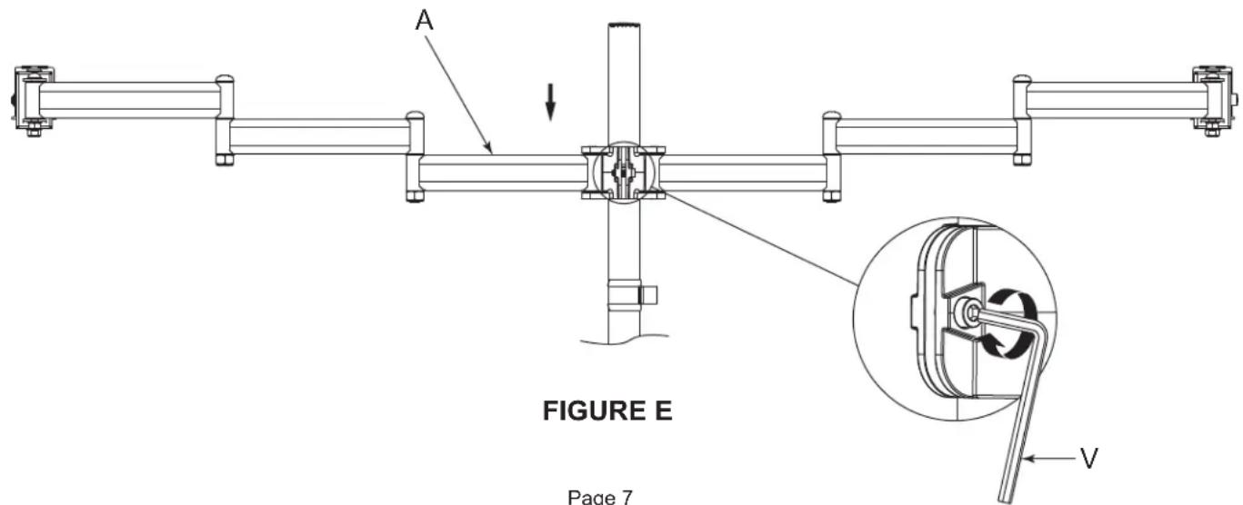
MOUNT ASSEMBLY
- Slide arm assembly (A) onto pole (B) as shown. (FIGURE E)
- Set assembly to desired height and tighten clamp screw to secure using 5mm hex key (V).
NOTE: If arm height is not known at this point, assembly can be moved by loosening the clamp screw.
MOUNT ASSEMBLY (CONTINUED)
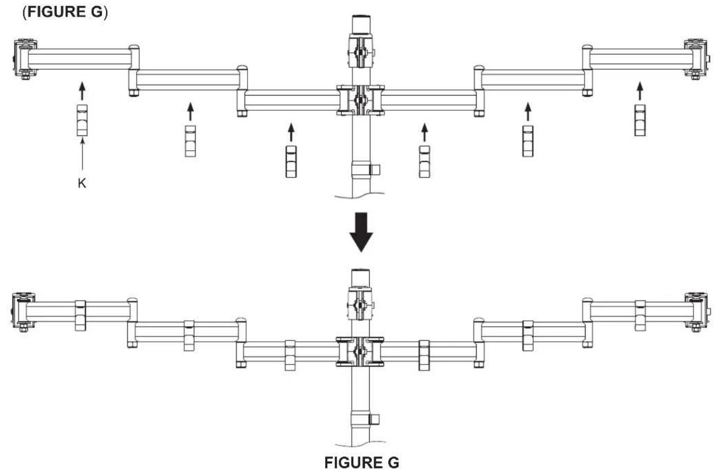
- Slide monitor mount knuckle (C) onto pole (B) as shown. (FIGURE F)
- Align monitor mount knuckle (C) with knuckles on arm assembly (A) adjust to dimension shown and tighten clamp screw to secure using 5mm hex key (V).
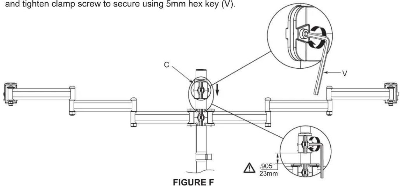
- Install (6x) arm cable clips (K) by snapping over each section of arm assembly as shown.
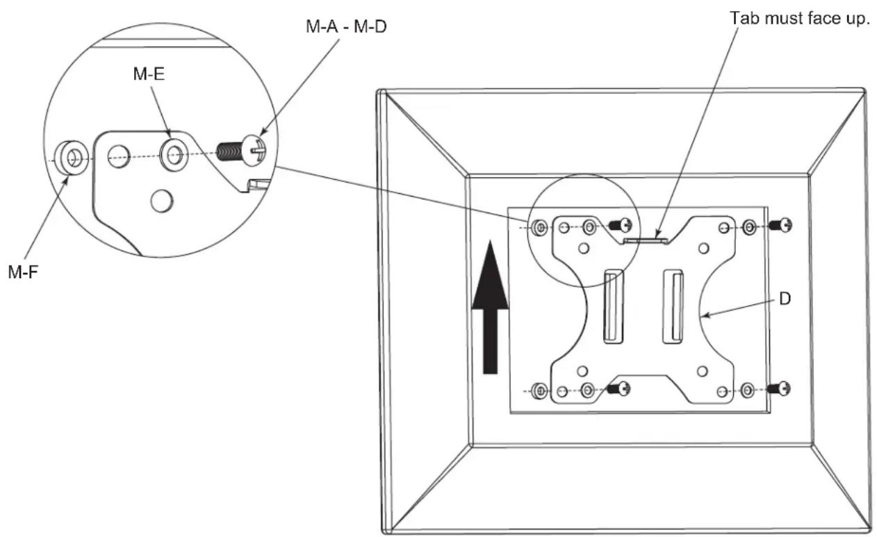
FLUSH DISPLAY MOUNT BRACKET INSTALLATION
- Using supplied display mount screws, select the appropriate screw size and length ensuring screw does not bottom out in mounting hole, or damage to display may occur.
NOTE: If you feel resistance, stop immediately and try a shorter screw. If supplied screws are still too long, use supplied spacers to take up slack.
- Align display mount bracket (D) with mounting holes on the back of display. Use (4x) display mount screws (M-A - M-D) and (4x) washers (M-E) to secure the display mount brackets to your display.
(FIGURE H)
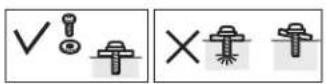
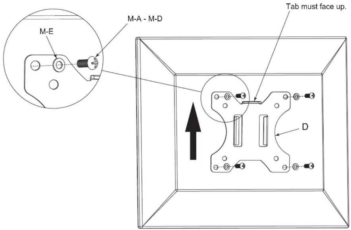
FIGURE H
RECESSED OR RAISED BACK DISPLAY MOUNT BRACKET INSTALLATION
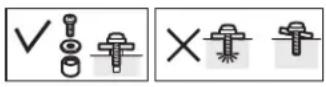
- Using supplied display mount screws, select the appropriate screw size and length ensuring screw does not bottom out in mounting hole, or damage to display may occur.
NOTE: If you feel resistance, stop immediately and try a shorter screw. If supplied screws are still too long, use supplied spacers to take up slack.
- Align display mount bracket (D) with mounting holes on the back of display. Use (4x) display mount screws (M-A - M-D), (4x) washers (M-E), and (4x) spacers (M-F) to secure the display mount brackets to your display. (FIGURE J)
MONITOR INSTALLATION
- With monitor attached, slide display mount hooks onto arm assembly knuckle plate as shown. Repeat for each monitor. (FIGURE K)
- Using (3x) thumb screws (J), secure display mount to each arm assembly.
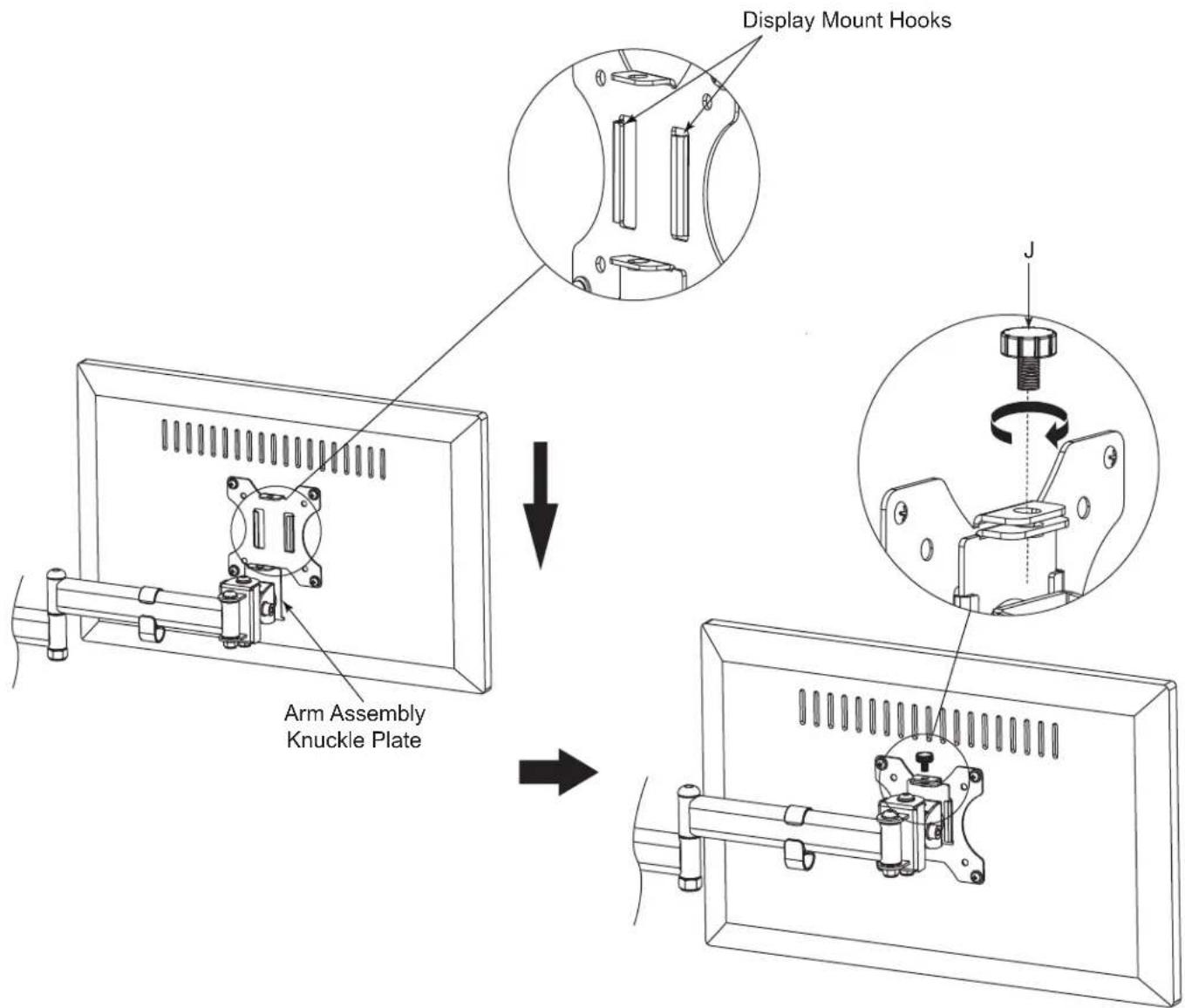
FIGURE K
ADJUSTMENT AND CABLE MANAGEMENT
- To adjust display angle, loosen socket cap screws on the side of the monitor mount knuckle using 6mm hex key (U) and retighten when desired angle is set. (FIGURE L)
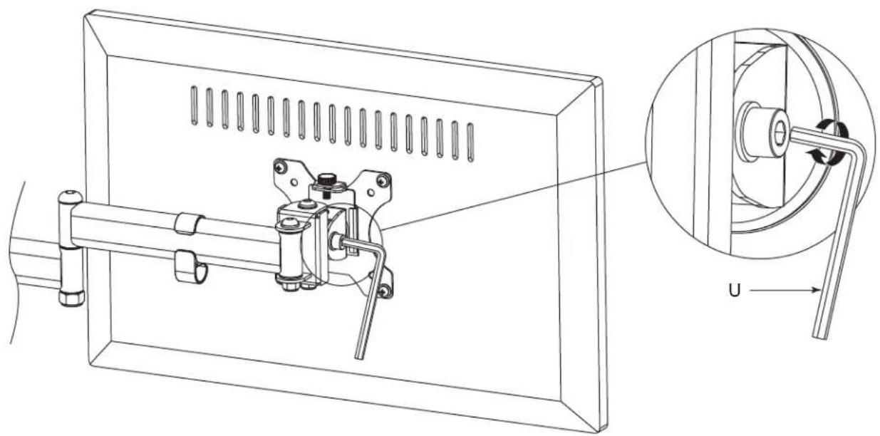
natural_image
Technical line drawing of a mechanical assembly with a magnified inset showing a rotating component (no text or symbols)FIGURE L
- Route cables through cable management clip (L). (FIGURE M)
NOTE: Cable management clip provides storage for supplied hex keys for future adjustment.
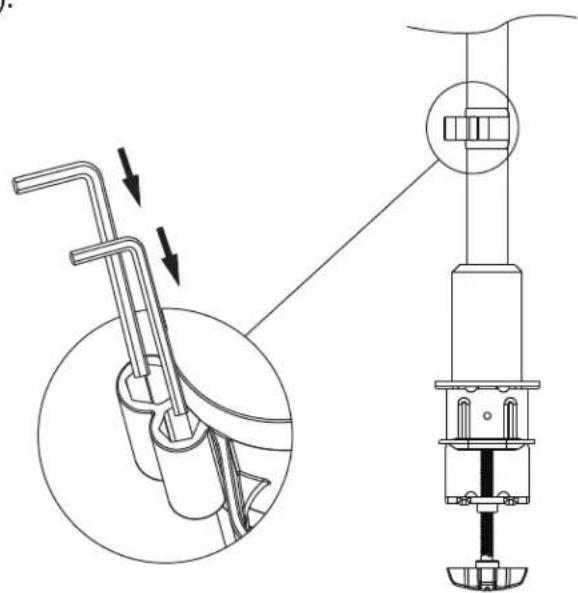
FIGURE M
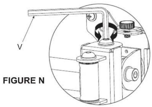
ADJUSTMENT AND CABLE MANAGEMENT (CONTINUED)
- To micro-adjust monitor heights, rotate button head screw on top of arm knuckle to raise or lower each monitor for alignment using 5mm hex key (V). (FIGURE N)
WARRANTY
For warranty information, refer to http://www.middleatlantic.com/company/about-us.aspx#warranty
Corporate Headquarters
Corporate Voice: 973-839-1011 - Fax: 973-839-1976 / International Voice: +1 973-839-8821 -
Middle Atlantic Canada
Voice: 613-836-2501 - Fax: 613-836-2690 / ca.middleatlantic.com -
customerservicecanada@middleatlantic.ca
Factory Distribution
USA: NJ - CA - IL Canada: ON - BC
At Middle Atlantic Products we are always listening. Your comments are welcome.
Middle Atlantic Products is an ISO 9001 and ISO 14001 Registered Company.

Middle Atlantic Products
what great systems are built on™
middleatlantic.com ■ 800.266.7225