
VIR1CF - Food Processor Vulcan - Free user manual and instructions
Find the device manual for free VIR1CF Vulcan in PDF.
| Product Type | Professional Gas Broiler |
| Brand | Vulcan |
| Model | VIR1CF |
| Category | Appliance |
| Gas Supply | Natural gas or propane |
| Electrical Supply | Required for some components (grounding mandatory) |
| Gas Pressure (Natural) | 1.49 kPa (6 inches of water column) |
| Gas Pressure (Propane) | 2.49 kPa (10 inches of water column) |
| Main Material | Stainless steel |
| Functions | Grilling, baking (depending on model) |
| Grilling Temperature | Reached in 90 seconds |
| Daily Cleaning | Mild soapy water or degreaser (do not use Dawn) |
| Stainless Steel Cleaning | Regular soap, rinse with hot water, wipe with a soft cloth |
| Burner Maintenance | Periodic cleaning by authorized technician |
| Lubrication | No lubrication required |
| Safety | Cut electrical power before cleaning, lockout/tagout |
| Minimum Clearances | Back: 152 mm (6 in) / Sides: 254 mm (10 in) / Floor: 152 mm (6 in) |
| Installation | Compliant with local codes, ANSI Z223.1, CSA B149.1 |
| Replacement Parts | Vulcan-Hart Service: 1 800 814-2028 |
| Maintenance Service | Contact Vulcan-Hart service or visit www.vulcanhart.com |
| First Use | Burn off protective oils at maximum power for 1 hour |
| Usage Tip | Turn off burners between cooking cycles to extend their lifespan |
Frequently Asked Questions - VIR1CF Vulcan
User questions about VIR1CF Vulcan
0 question about this device. Answer the ones you know or ask your own.
Ask a new question about this device
Download the instructions for your Food Processor in PDF format for free! Find your manual VIR1CF - Vulcan and take your electronic device back in hand. On this page are published all the documents necessary for the use of your device. VIR1CF by Vulcan.
USER MANUAL VIR1CF Vulcan
natural_image
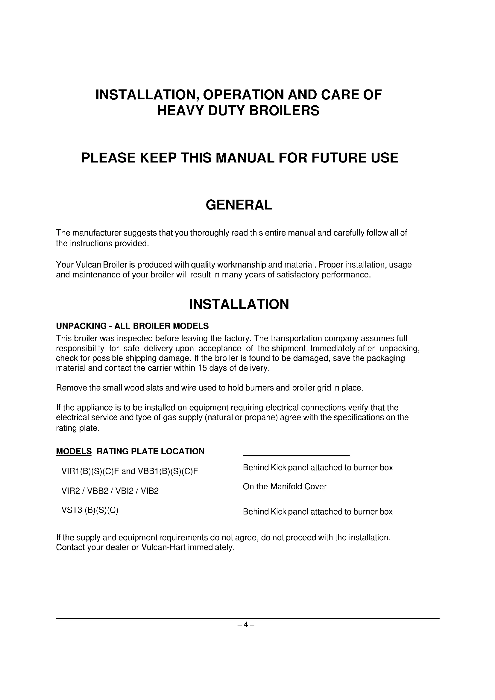
Line drawing of a multi-tiered stainless steel oven with cooling unit and side-mounted rack (no text or symbols)OPERATIONS MANUAL
V-SERIES HDR BROILERS
IR BURNER MODELS
VIR1 (B)(S)(C) F VIR2
VBB (B)(S)(C) F VBB2
RADIANT BURNER MODELS
VBI2 VIB2
VST3 (B)(S)(C)
**For Oven Operations and Installation Information refer to the "V Series HDR" Operations Manual F-37403
- NOTICE -
This manual is prepared for use by trained service technicians and should not be used by those not properly qualified. If you have attended a service school for this product, you may still be qualified to perform the procedures described in this manual. This manual is not intended to be all encompassing. If you have not attended a service school for this product, you should read, in its entirety, the repair procedure you wish to perform to determine if you have the necessary tools, instruments and skills required to perform the procedure. Procedures for which you do not have the necessary tools, instruments and skills should be performed by a trained service technician.
For additional information on Vulcan- Hart or to locate an authorized parts and service provider in your area, visit our website at www.VulcanEquipment.com.
VULCAN-HART
DIVISION OF ITW FOOD EQUIPMENT GROUP, LLC
3600 NORTH POINT BLVD.
BALTIMORE, MD 21222
IMPORTANT FOR YOUR SAFETY
THIS MANUAL HAS BEEN PREPARED FOR PERSONNEL QUALIFIED TO INSTALL GAS EQUIPMENT, WHO SHOULD PERFORM THE INITIAL FIELD START-UP AND ADJUSTMENTS OF THE EQUIPMENT COVERED BY THIS MANUAL.
POST IN A PROMINENT LOCATION THE INSTRUCTIONS TO BE FOLLOWED IN THE EVENT THE SMELL OF GAS IS DETECTED. THIS INFORMATION CAN BE OBTAINED FROM THE LOCAL GAS SUPPLIER.
IMPORTANT
IN THE EVENT A GAS ODOR IS DETECTED, SHUT DOWN UNITS AT MAIN SHUTOFF VALVE AND CONTACT THE LOCAL GAS COMPANY OR GAS SUPPLIER FOR SERVICE.
FOR YOUR SAFETY
DO NOT STORE OR USE GASOLINE OR OTHER FLAMMABLE VAPORS OR LIQUIDS IN THE VICINITY OF THIS OR ANY OTHER APPLIANCE.
WARNING: IMPROPER INSTALLATION, ADJUSTMENT, ALTERATION, SERVICE OR MAINTENANCE CAN CAUSE PROPERTY DAMAGE, INJURY OR DEATH. READ THE INSTALLATION, OPERATING AND MAINTENANCE INSTRUCTIONS THOROUGHLY BEFORE INSTALLING OR SERVICING THIS EQUIPMENT.
IN THE EVENT OF A POWER FAILURE, DO NOT ATTEMPT TO OPERATE THIS APPLIANCE. IN THE EVENT OF POWER FAILURE, SHUT OFF GAS TO ALL BURNERS TO PREVENT THE FLOW OF UN-IGNITED GAS TO BURNERS WHEN POWER IS RESTORED. PILOTS REQUIRING MANUAL LIGHTING WILL HAVE TO BE RE-LIT WHEN POWER WHEN GAS FLOW IS RESTORED AFTER A POWER FAILURE.
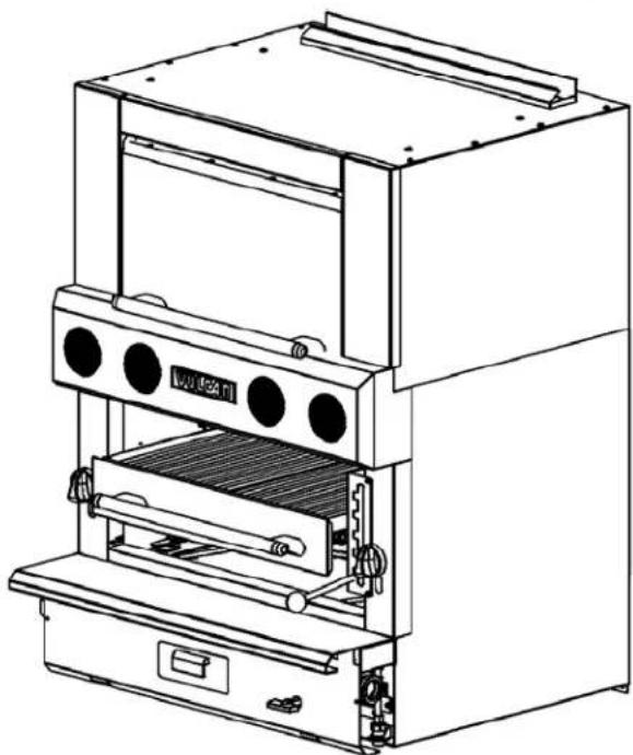
STOP BOLTS
natural_image
Close-up of a metallic industrial machine with a grid-patterned base and metal frame (no visible text or symbols)IMPORTANT
STOP BOLTS MUST BE IN POSITION FOR SAFE OPERATION OF GRID. IF DAMAGED OR MISSING, REPLACE AT ONCE. DO NOT OPERATE GRID WITHOUT BOLTS.
INSTALLATION, OPERATION AND CARE OF HEAVY DUTY BROILERS
PLEASE KEEP THIS MANUAL FOR FUTURE USE
GENERAL
The manufacturer suggests that you thoroughly read this entire manual and carefully follow all of the instructions provided.
Your Vulcan Broiler is produced with quality workmanship and material. Proper installation, usage and maintenance of your broiler will result in many years of satisfactory performance.
INSTALLATION
UNPACKING - ALL BROILER MODELS
This broiler was inspected before leaving the factory. The transportation company assumes full responsibility for safe delivery upon acceptance of the shipment. Immediately after unpacking, check for possible shipping damage. If the broiler is found to be damaged, save the packaging material and contact the carrier within 15 days of delivery.
Remove the small wood slats and wire used to hold burners and broiler grid in place.
If the appliance is to be installed on equipment requiring electrical connections verify that the electrical service and type of gas supply (natural or propane) agree with the specifications on the rating plate.
MODELS RATING PLATE LOCATION
VIR1(B)(S)(C)F and VBB1(B)(S)(C)F
VIR2 / VBB2 / VBI2 / VIB2
VST3 (B)(S)(C)
Behind Kick panel attached to burner box
On the Manifold Cover
Behind Kick panel attached to burner box
If the supply and equipment requirements do not agree, do not proceed with the installation. Contact your dealer or Vulcan-Hart immediately.
LOCATION
The equipment area must be kept free and clear of combustible substances.
This broiler is design certified for installation with the following minimum clearances from combustible and noncombustible adjacent wall construction:
| ALL MODELS: | Combustible | Non-Combustible | |
| Back | 6 in | 6 in | |
| VIR1(B)(S)(C)F and VBB1(B)(S)(C)F | RH Side | 10 in | 0 in |
| VIR2 / VBB2 / VBI2 / VIB2 | LH Side | 10 in | 0 in |
| VST3 (B)(S)(C) | Floor | 6 in | 6 in |
The installation location must allow adequate clearances for servicing and proper operation. A minimum front clearance of 35" (889 mm) is required.
Ensure the appliance area is kept free and clear from combustibles.
Do not obstruct the flow of combustion and ventilation air. Adequate clearance for air openings into the combustion chamber must be provided. Make sure there is an adequate supply of air in the room to replace air taken by ventilating systems and allow for combustion gas at the broiler burners.
IMPORTANT INSTALLATION NOTE: For any countertop device, please additionally use instructions provided in document 962928 COUNTERTOP RANGE INSTALLATION.
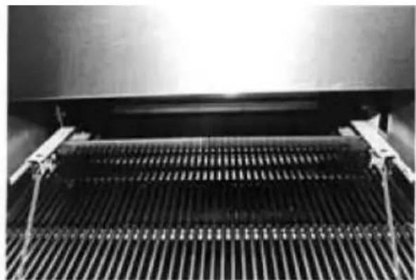
CERAMIC RADIANT BRICK INSTALLATION
VBB and VST models are shipped with radiant ceramic bricks in a separate box packed inside the broiler or oven sections. Remove this box and unpack bricks. Handle bricks carefully as the ceramic is fragile and easily cracked.
There are 18 total bricks and should be placed on the rails alongside the burners as shown.
When properly installed, there should be three bricks on each rail, and they should be placed so as to be centered on the rail.
natural_image
3D rendering of three industrial machinery units mounted on a conveyor belt system (no visible text or symbols)INSTALLATION CODES AND STANDARDS - ALL BROILER MODELS
Your broiler must be installed in accordance with:
In the United States:
-
State and local codes.
-
National Fuel Gas Code, ANSI/Z223.1/NFPA #54 (latest edition). Copies may be obtained from The American Gas Association, Accredited Standards Committee Z223 @ 400 N. Capital St. NW, Washington, DC 2001 or the Secretary Standards Council, NFPA, 1 Batterymarch Park, Quincy, MA 02169-7471.
NOTE: In the Commonwealth of Massachusetts, All gas appliances vented through a ventilation hood or exhaust system equipped with a damper or with a power means of exhaust shall comply with 248 CMR.
-
Vapor Removal From Cooking Equipment, NFPA #96 (latest edition). Copies may be obtained from The National Fire Protection Association, Batterymarch Park, Quincy MA 02169-7471.
-
National Electrical Code, ANSI/NFPA-70 (latest edition). Copies may be obtained from The National Fire Protection Association, Batterymarch Park, Quincy, MA 02169-7471.
In Canada:
-
Local codes.
-
CSA B149.1 Natural Gas and Propane Installation Code.
-
CSA C22.1 Canadian Electrical Code (latest edition). The above are available from The Canadian Standard Association, 5060 Spectrum Way, Suite 100, Mississauga, Ontario, Canada L4W 5N6.
BROILERS MOUNTED ON CASTERS
Broilers mounted on casters must use a flexible connector (not supplied by Vulcan) that complies with the Standard for Connectors for Movable Gas Appliances, ANSI Z21.69 • CSA 6.16 and a quick-disconnect device that complies with the Standard for Quick -Disconnect Devices for Use With Gas Fuel, ANSI -Z21.41 • CSA 6.9. In addition, adequate means must be provided to limit movement of the appliance without depending on the connector and the quick-disconnect device or its associated piping to limit appliance movement. Attach the restraining device at the rear of the broiler.
If disconnection of the restraint is necessary, turn off the gas supply before disconnection. Reconnect this restraint prior to turning the gas supply on and returning the broiler to its installation position.
Separate instructions for installing casters to the broiler are included with the casters.
Note: If the broiler is installed on casters and is moved for any reason, it is recommended that the broiler be re-leveled front to back and side to side.
LEVELING AND CONNECTING MANIFOLDS - ALL MODELS
-
Place the broiler in its exact position or battery lineup.
-
Using a carpenter level, level the broiler from front to rear and from side to side. Unless the broilers are level, they will not give proper cooking results, and equipment being battered will not draw up tight.
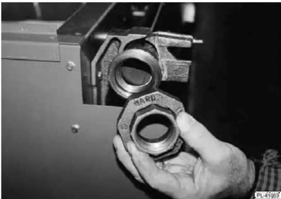
If you are installing a new battery appliance to an existing field appliance, the union on the existing field appliance must be checked against the union being used on the new range. The union manufacturer's name around the face surface of the union nut must match.
natural_image
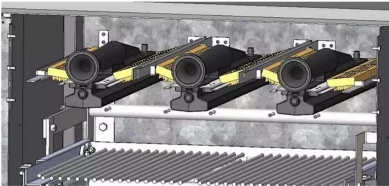
Close-up of a hand holding a metallic mechanical component, no visible text or symbolsFig. 15
-
Engage union nut on manifold pipe of the broiler with the male fitting on the next unit, and draw up union hand-tight. Be sure units butt both front and rear.
-
Continue to level up and connect manifold pipe until all broilers in the battery are connected, then tighten all manifold unions gas-tight.
Questions or concerns regarding the installation procedures may be addressed by calling the Vulcan-Hart Service Department 1-800-814-2028.
GAS CONNECTIONS
CAUTION: All gas supply connections and any pipe joint compound used must be resistant to the action of propane gases.
Connect gas supply to the broiler(s). Make sure the pipes are clean and free of obstructions, dirt and piping compound.
Codes require that a gas shutoff valve be installed in the gas line ahead of the broiler.
Natural gas broilers and propane gas broilers are equipped with fixed orifices and no adjustment is necessary.
Pressure regulators are required on all Vulcan Broilers. Regulators must have an outlet pressure of 6" (1.49 mb) Water Column for natural gas supply and 10" (2.49 mb) Water Column for propane gas.
Unless the manifold pressure on all connected appliances is the same, a separate pressure regulator must be supplied for each appliance(s) having a different manifold pressure(s).
The regulators must have:
• C.S.A. design certification.
• Enough regulation capacity for the total connected gas load.
- Pressure adjustment range to allow adjustment for the manifold pressure marked on the rating plate.
WARNING: PRIOR TO LIGHTING, CHECK ALL JOINTS IN THE GAS SUPPLY LINE FOR LEAKS. USE SOAP AND WATER SOLUTION. DO NOT USE AN OPEN FLAME.
Ensure that burner heads are connected to burner base.
After piping has been checked for leaks, all piping receiving gas should be fully purged to remove air.
TESTING THE GAS SUPPLY SYSTEM
When test pressures exceed 12 psig (3.45 kPa), the broiler and its individual shutoff valve must be disconnected from the gas supply piping system.
When test pressures are 12 psig (3.45 kPa) or less, the broiler must be isolated from the gas supply system by closing its individual manual shutoff valve.
FLUE CONNECTIONS
DO NOT obstruct the flow of flue gases from the flue duct located on the rear of the broiler. It is recommended that the flue gases be ventilated to the outside of the building through a ventilation system installed by qualified personnel.
From the termination of the broiler flue vent to the filters of the hood venting system, an 18" (457 mm) minimum clearance must be maintained.
Information on the construction and installation of ventilating hoods may be obtained from the standard for "Vapor Removal from Cooking Equipment," NFPA No. 96 (latest edition), available from the National Fire Protection Association, Batterymarch Park, Quincy, MA 02269.
ELECTRICAL CONNECTIONS
WARNING: ELECTRICAL AND GROUNDING CONNECTIONS MUST COMPLY WITH THE APPLICABLE PORTIONS OF THE NATIONAL ELECTRICAL CODE AND/OR OTHER LOCAL ELECTRICAL CODES.
WARNING: DISCONNECT THE ELECTRICAL POWER TO THE MACHINE AND FOLLOW LOCKOUT / TAGOUT PROCEDURES
WARNING: APPLIANCES EQUIPPED WITH A FLEXIBLE ELECTRIC SUPPLY CORD ARE PROVIDED WITH A THREE-PRONG GROUNDING PLUG. IT IS IMPERATIVE THAT THIS PLUG BE CONNECTED INTO A PROPERLY GROUNDED THREE-PRONG RECEPTACLE. IF THE RECEPTACLE IS NOT THE PROPER GROUNDING TYPE, CONTACT AN ELECTRICIAN. DO NOT REMOVE THE GROUNDING PRONG FROM THIS PLUG.
Do not connect broiler to electrical supply until after gas connections have been made.
For OVEN SECTION LIGHTING INSTRUCTIONS see Operations and Maintenance Manual Lighting Instructions Section (F-37403).
LIGHTING INSTRUCTIONS - BROILER SECTIONS
- Ensure that gas supply to appliance (lower chrome handle) and IR broiler burners (round chrome knobs) are OFF.
- Turn ON gas supply to appliance.
- Turn ON gas supply to broiler.
- Turn ON broiler burner valves to purge air.
- Turn OFF broiler burner valves and gas supply to broiler.
- Wait 30 seconds, turn ON gas supply to broiler.
- Using a taper or wand, light the pilots.
- If pilot fails to light, shut off all gas, wait 5 minutes and repeat steps 1-7.
- Turn broiler burner valves on full to light main burner.
OPERATION
WARNING: THE BROILER AND ITS PARTS ARE HOT. USE CARE WHEN OPERATING, CLEANING, AND SERVICING THE BROILER.
CONTROLS
Finishing Oven Door Option and Handle
Grid Positioning Handle
— Counterbalanced for easy opening. To open, lift the door handle up. To close the door, pull the handle straight down.
— Allows grid assembly to be adjusted to the proper level depending on the product being prepared. The higher the positioning of the grid, the closer the product will be to the burner flame.
To relocate the grid position, grasp the grid lever arm and push the handle to the right of the index plate. Glide the arm up or down to the desired location. Push the lever arm handle to the left location. Push the lever arm and lock the arm into the proper slot.
Broiler Grid Handle
— Allows the operator to pull the grid clear of the heat zone, but does not allow the grid to be completely removed from the broiler. When the product is to be removed from the heat zone, pull the grid handle straight out. The grid assembly, which is on roller bearings, will slide out until it locks into place. To return the grid assembly to the broiling compartment, pull the grid handle slightly up and push straight back (Fig. 22).
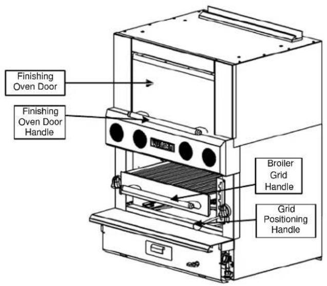
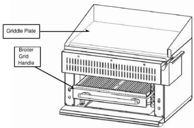
Fig. 22
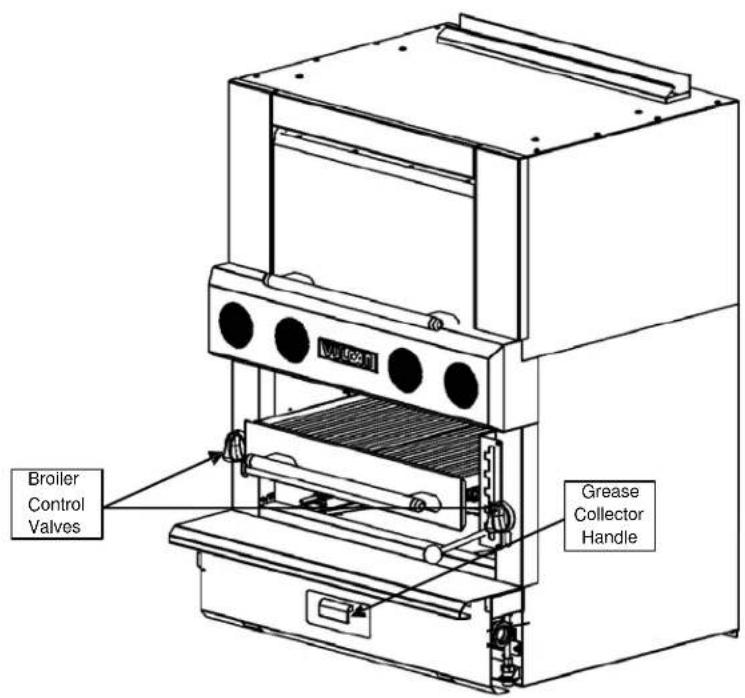
Broiler Control Valve
— Regulates the flow of gas to the broiler burner. To operate the valve, turn it counterclockwise. Turn the knob clockwise to the OFF position to shut burners down.
Grease Collector Handle —
The grease pan must be checked frequently and emptied when it is about 3/4 full. To check or empty the grease collector pan, pull the grease collector handle straight out until the pan is partially exposed. If the grease pan is being emptied, carefully remove the grease pan completely from the broiler. Dispose of the grease and return the pan to the broiler before continuing to broil.
BEFORE FIRST USE
Burn off protective grid oils before cooking food products. With grid in full-up position, operate broiler at full output for approximately 1 hour or until smoking stops. The burning will cause a somewhat unpleasant odor; this is normal.
COOKING
Preheat broiler for approx. 15 minutes. Burner life will be extended if the burners are turned off between cooking periods.
Select the desired grid position and gas setting. It is recommended that gas input be reduced first when lower grid temperatures are desired. Further reduction in grid temperatures, if necessary, can then be obtained by lowering the grid position to any one of the several grid positions.
Pull the broiler grid handle straight out to slide the grid assembly out for loading. After loading product, pull the grid handle slightly up and push straight back to return the grid assembly to the cooking chamber.
USING THE BROILER
Initiation of the cooking cycle and shutdown procedures are as follows:
To Start
- Turn left and/or right gas valve on.
Nightly Shutdown
- Turn the left and/or right valve OFF.
Complete Shutdown
Perform Steps 1 of nightly shutdown instructions, and then turn incoming gas valve to OFF position.
CLEANING
WARNING: DISCONNECT THE ELECTRICAL POWER TO THE MACHINE AND FOLLOW LOCKOUT / TAGOUT PROCEDURES.
Daily
Exterior
Clean the exterior finish of the broiler with a mild soap solution or similar grease-dissolving material. DO NOT use Dawn Dish Detergent.
Broiler
Clean the broiler and doors, especially if fruit pies or tomato sauce were baked or meats roasted, or if there have been any spillovers.
Stainless Steel
Routine cleaning of stainless steel may be done with ordinary soap or detergent and water. DO NOT use Dawn Dish Detergent. To prevent water spots and streaks, rinse the broiler thoroughly with warm water and wipe dry with a soft, clean cloth. The addition of a rinsing agent will also help prevent spotting.
When scraping off heavy deposits of grease or oil from stainless steel broilers, use stainless steel, wood, plastic or rubber tools. Never use ordinary steel scrapers, knives or plain steel wool.
Fingerprints may be minimized by applying a cleaner that will leave a thin, oily or waxy film. Wipe the cleaner on and remove the excess with a soft, dry cloth. Subsequent fingerprints will usually disappear when wiped lightly with a soft, dry cloth containing a little of the cleaner. If the surface is especially dirty to start with, wash first with soap or detergent and water.
Soaking with hot, soapy water will help greatly to remove burned- on foods and grease. Stubborn deposits can be removed with scouring powder mixed into a paste and applied with stainless steel wool or sponges. Do not use ordinary steel wool because particles that remain can eventually rust and cause unsightly spots and stains. Rub in the direction of the polish lines.
Straw -colored or slightly darkened areas may appear on stainless steel appliances where temperatures reach 500^ F ( 260^ C) or more. This "heat tint" is caused by a slight oxidation of the stainless steel and is not harmful.
To control or minimize this condition, never use more heat than is absolutely necessary. Do not use oversize pots where whipping of the flames will occur.
Heat tint can be partially removed by scouring vigorously with stainless steel wool and a paste made of scouring powder or stainless cleaner. Rub in the direction of the polish lines.
MAINTENANCE
WARNING: THE BROILER AND ITS PARTS ARE HOT. USE CARE WHEN OPERATING, CLEANING, AND SERVICING THE BROILER.
WARNING: DISCONNECT THE ELECTRICAL POWER TO THE MACHINE AND FOLLOW LOCKOUT / TAGOUT PROCEDURES.
The efficient operation of this broiler depends upon a rather delicate balance between the volume of gas and the supply of air. Unless complete combustion of the gas is achieved, poor operating characteristics and excessive gas consumption can occur.
Periodic cleaning of the burners by an authorized servicer is recommended.
LUBRICATION
No lubrication is needed.
TROUBLESHOOTING
CHECKS TO BE MADE BEFORE CALLING THE SERVICER
- Ensure main gas supply is on to the unit.
- Ensure pilot light is lit.
SERVICE AND PARTS INFORMATION
To obtain service and parts information concerning this charbroiler, contact the Authorized Service Agency in your area (refer to our website, www.vulcanhart.com for a complete listing of Authorized Service and Parts depots) or contact 1-800-814-2028 for Technical Service and Parts Assistance.
When calling for service, the following information must be available: model number, serial number, manufactures date (MD) and voltage.
This manual should be retained for future reference.
NOTES
NOTES
ENTRETIEN
AVERTISSEMENT : LE GRILLOIR ET SES COMPOSANTS SONT CHAUDS. EXERCER UNE EXTRÊME PRUDENCE LORS DE L'EXPLOITATION, DU NETTOYAGE ET DE L'ENTRETIEN DE CET APPAREIL.
AVERTISSEMENT : COUPER L'ALIMENTATION ÉLECTRIQUE DE L'APPAREIL ET SUIVRE LES PROCÉDURES DE VERROUILLAGE ET D'ÉTIQUETAGE.
RACCORDEMENT DU CONDUIT D'ÉVACUATION
natural_image
Close-up of a hand holding a metallic mechanical component, no visible text or symbolsFig. 15
natural_image
3D rendering of industrial conveyor systems with three cylindrical components mounted on metal frames (no visible text or symbols)EMPLACEMENT
VIR1(B)(S)(C)F and VBB1(B)(S)(C)F
natural_image
Close-up of a metallic industrial machine with a grid-patterned base and metal frame (no visible text or symbols)IMPORTANT
LES BOULONS D'ARRÊT DOIVENT ÊTRE EN PLACE POUR QUE LA GRILLE PUISSE FONCTIONNER EN TOUTE SÉCURITÉ.
S'ILS SONT ENDOMMAGÉS OU MANQUANTS, LES REMPLACER IMMÉDIATEMENT.
NE PAS FAIRE FONCTIONNER LA GRILLE SANS CES BOULONS.
MESURES DE SÉCURITÉ IMPORTANTES
CE MANUEL A ÉTÉ PRÉPARÉ À L'INTENTION D'UN PERSONNEL QUALIFIÉ ET AUTORISÉ À INSTALLER DES APPAREILS FONCTIONNANT AU GAZ ET À EFFECTUER LE DÉMARRAGE INITIAL CHEZ LE CLIENT DE MÊME QUE LE RÉGLAGE DES APPAREILS CONCERNÉS DANS CE MANUEL
AFFICHER À UN ENDROIT VISIBLE LES PREMIERS SOINS À ADMINISTRER À TOUTE PERSONNE AYANT RESPIRÉ LES GAZ QUE CET APPAREIL DÉGAGE. ON PEUT SE PROCURER CES INFORMATIONS CHEZ LE FOURNISSEUR DE GAZ LE PLUS PRÈS.
IMPORTANT
EN CAS D'ODEURS DE GAZ, ÉTEINDRE L'APPAREIL PAR LE ROBINET D'ARRÊT PRINCIPAL ET COMMUNIQUER AVEC LA COMPAGNIE DE GAZ LA PLUS PRÈS OU AVEC LE FOURNISSEUR DE GAZ ATTITRÉ POUR L'ENTRETIEN.
MESURE DE SÉCURITÉ
NE PAS RANGER NI UTILISER DE L'ESSENCE NI TOUT AUTRE LIQUIDE OU VAPEUR INFLAMMABLE À PROXIMITÉ DE CET APPAREIL OU DE TOUT AUTRE APPAREIL.
AVERTISSEMENT
L'INSTALLATION, LE RÉGLAGE, LA MODIFICATION ET L'ENTRETIEN INCORRECTS DE CET APPAREIL PEUVENT CAUSER DES DOMMAGES MATÉRIELS, DES BLESSURES ET MÊME LA MORT. LIRE LES INSTRUCTIONS D'INSTALLATION, DE FONCTIONNEMENT ET D'ENTRETIEN AVANT DE PROCÉDER À TOUTE INSTALLATION OU TOUT ENTRETIEN.
EN CAS DE PANNE DE COURANT, NE PAS FAIRE FONCTIONNER CET APPAREIL. FERMER LE ROBINET DE GAZ DE TOUS LES BRÛLEURS POUR PRÉVENIR LE DÉBIT DE GAZ ACCUMULÉ AUX BRÛLEURS LORSQUE L'ALIMENTATION SERA RÉTABLIE. APRÈS UNE PANNE DE COURANT, LES VEILLEUSES QUI EXIGENT UN ALLUMAGE MANUEL DEVORNT ÊTRE ALLUMÉES À NOUVEAU LORSQUE LE DÉBIT DE GAZ SERA RÉTABLI.
natural_image
Line drawing of a multi-tiered stainless steel oven with cooling unit and side-mounted rack (no text or symbols)GRILLOIRS HDR
DE LA SÉRIE V
INFRAROUGE MODELES
VIR1 (B)(S)(C) F
VIR2
VBB (B)(S)(C) F
VBB2
RAYONNANT MODELES
VBI2
VIB2
VST3 (B)(S)(C)
- OPERATIONS MANUAL
- V-SERIES HDR BROILERS
- - NOTICE -
- IMPORTANT FOR YOUR SAFETY
- IMPORTANT
- FOR YOUR SAFETY
- STOP BOLTS
- INSTALLATION, OPERATION AND CARE OF HEAVY DUTY BROILERS
- PLEASE KEEP THIS MANUAL FOR FUTURE USE
- GENERAL
- INSTALLATION
- UNPACKING - ALL BROILER MODELS
- MODELS RATING PLATE LOCATION
- LOCATION
- CERAMIC RADIANT BRICK INSTALLATION
- INSTALLATION CODES AND STANDARDS - ALL BROILER MODELS
- In the United States:
- In Canada:
- BROILERS MOUNTED ON CASTERS
- LEVELING AND CONNECTING MANIFOLDS - ALL MODELS
- GAS CONNECTIONS
- CAUTION: All gas supply connections and any pipe joint compound used must be resistant to the action of propane gases.
- TESTING THE GAS SUPPLY SYSTEM
- FLUE CONNECTIONS
- ELECTRICAL CONNECTIONS
- LIGHTING INSTRUCTIONS - BROILER SECTIONS
- OPERATION
- CONTROLS
- Broiler Control Valve
- Grease Collector Handle —
- BEFORE FIRST USE
- COOKING
- USING THE BROILER
- To Start
- Nightly Shutdown
- Complete Shutdown
- CLEANING
- Daily
- Exterior
- Broiler
- Stainless Steel
- MAINTENANCE
- LUBRICATION
- TROUBLESHOOTING
- CHECKS TO BE MADE BEFORE CALLING THE SERVICER
- SERVICE AND PARTS INFORMATION
- NOTES
- ENTRETIEN
- RACCORDEMENT DU CONDUIT D'ÉVACUATION
- EMPLACEMENT
- MESURES DE SÉCURITÉ IMPORTANTES
- MESURE DE SÉCURITÉ
- AVERTISSEMENT
- GRILLOIRS HDR
- DE LA SÉRIE V
- INFRAROUGE MODELES
- RAYONNANT MODELES
Brand : Vulcan
Model : VIR1CF
Category : Food Processor