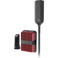
weBoost Drive Reach RV - TV signal amplifier Wilson - Free user manual and instructions
Find the device manual for free weBoost Drive Reach RV Wilson in PDF.


| Technical Features | TV signal amplifier for recreational vehicles, compatible with 4G LTE and 3G networks. |
|---|---|
| Range | Up to 50 miles range to capture TV signals. |
| Supported Frequencies | Supports frequency bands from 600 MHz to 6 GHz. |
| Installation | Easy installation with included mounting kit, designed for outdoor use. |
| Power Supply | Powered by AC adapter or via cigarette lighter socket. |
| Usage | Ideal for motorhomes, caravans, and other recreational vehicles. |
| Maintenance | Regularly check connections and clean antennas for optimal operation. |
| Safety | Follow electrical safety standards during installation and use. |
| Warranty | 2-year limited warranty against manufacturing defects. |
| General Information | Compatible with most TVs and TV receivers, check compatibility before purchase. |
Frequently Asked Questions - weBoost Drive Reach RV Wilson
User questions about weBoost Drive Reach RV Wilson
0 question about this device. Answer the ones you know or ask your own.
Ask a new question about this device
Download the instructions for your TV signal amplifier in PDF format for free! Find your manual weBoost Drive Reach RV - Wilson and take your electronic device back in hand. On this page are published all the documents necessary for the use of your device. weBoost Drive Reach RV by Wilson.
USER MANUAL weBoost Drive Reach RV Wilson
ENGLISH | FRANÇAIS Installation Guide
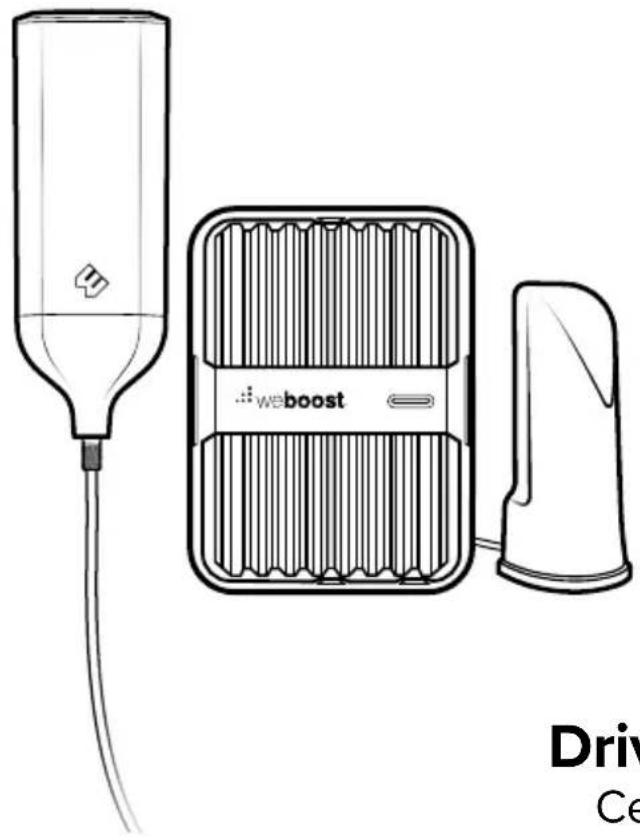
Drive Reach RV
Cell Signal Booster
Index
Package Contents 1
STEP 1 Mount Outside Antenna & Route Cable 2
STEP 2 Connect Cable to Outside Antenna 6
STEP 3 Inside Antenna Location 6
STEP 4 Booster Location & Connect Cables 7
STEP 5 Connect Power Supply to Booster 7
Booster Light Patterns 8
Troubleshooting 10
Safety Guidelines 12
Specifications 15
Warranty. 16
Package Contents
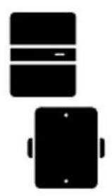
Drive Reach Signal Booster & Bracket
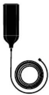
Outside Antenna & 7.6 m RG-6 Cable

Inside Antenna
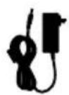
Power Supply
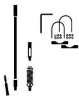
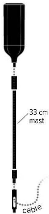
33 cm Mast Extension, Side-Exit Adapter, Spring, L-Bracket Mount & Thread Lock Pack
STEP 1 Mount Outside Antenna & Route Cable
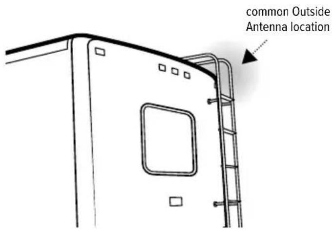
Determine where you want the Outside Antenna on your RV. Mount Outside Antenna to a ladder or pole so that the entire Outside Antenna is above the roof line of the RV and clear of other metal obstructions.
Important
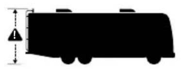
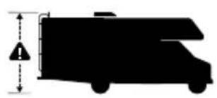
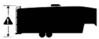
NOTE: Keep in mind to stay below the maximum height limit allowed by law in your area (generally 4.1m to 4.2m ).
STEP 1 cont.)
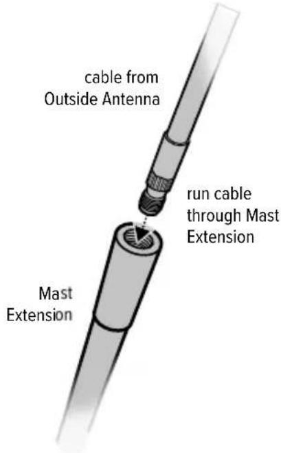
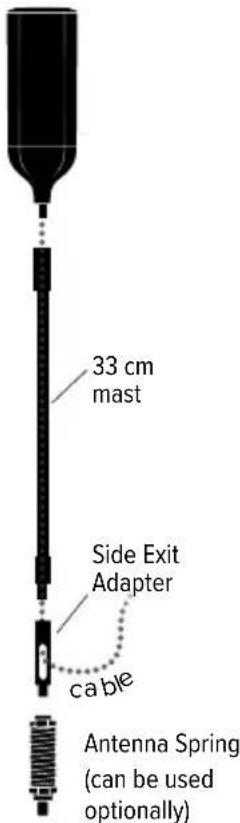
To assemble the Outside Antenna, insert cable through Mast Extension then through Side Exit Adapter.
NOTE: Antenna Spring can be used optionally.
ENGLISH
STEP 1 cont.)
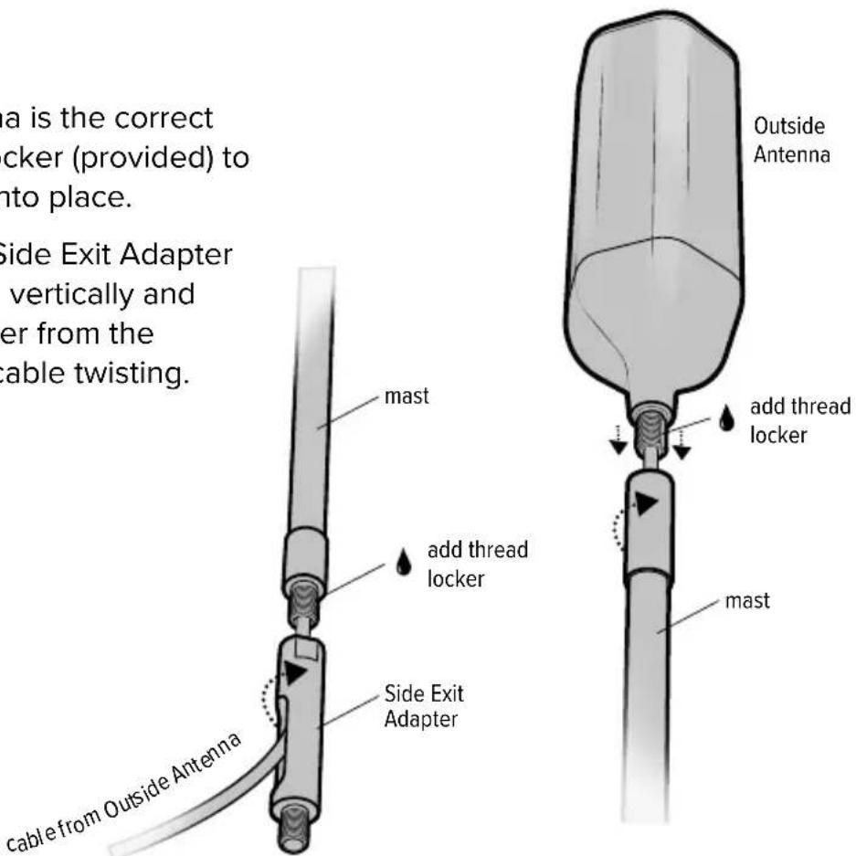
Verify the Outside Antenna is the correct height, if so, use thread locker (provided) to thread points and screw into place.
NOTE: When adding the Side Exit Adapter hold the Outside Antenna vertically and screw the Side Exit Adapter from the bottom up. This reduces cable twisting.
STEP 1 cont.)
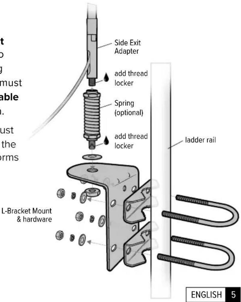
Mount Outside Antenna. L-Bracket Mount and hardware is provided to mount to ladder or pole. If installing with Spring, the Side Exit Adapter must be used. Then route 7.6 m RG-6 cable from inside RV to Outside Antenna.
NOTE: Outside Antenna location must be within reach of the booster with the 7.6m coax cable. The system performs best with maximum vertical and horizontal separation.
STEP 2 Connect Cable to Outside Antenna
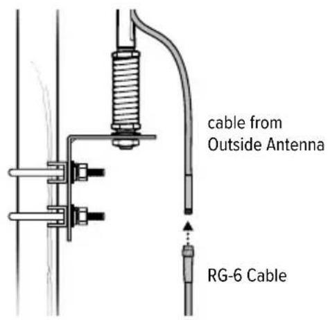
After routing the RG-6 Cable into the RV, connect the cable to the Outside Antenna.
STEP 3 Inside Antenna Location
Place Inside Antenna where stronger signal is desired in the RV.
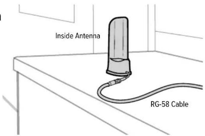
6 ENGLISH
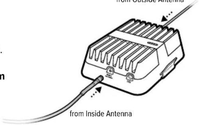
STEP4 Booster Location & Connect Cables
Find a location to place the Drive Reach Booster and secure it with provided Bracket. Connect cable from Outside Antenna to labeled booster port and connect cable from Inside Antenna to labeled booster port.
from Outside Antenna
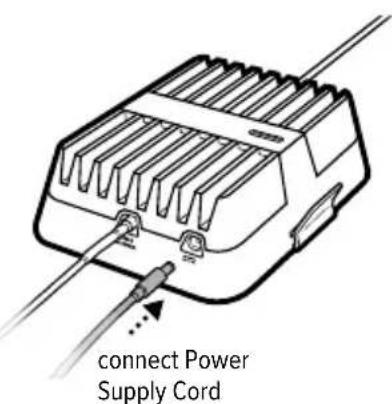
STEP5 Connect Power Supply to Booster
Connect the power supply cord to the end of the Booster, labeled “ ”, and connect into a 110V wall plug. Enjoy your boosted signal!

ENGLISH
Booster Light Patterns
SOLID GREEN
This indicates that your Drive Reach Booster is functioning properly and there are no issues with installation.
SOLID RED
Band has shutoff. This is due to a feedback loop condition called oscillation. This is a built in safety feature that causes a band to shut off to prevent harmful interference with a nearby cell tower. Refer to Troubleshooting section.
BLINKING RED, THEN SOLID GREEN
This indicates that one or more of the booster bands has reduced power due to a minor feedback loop condition called oscillation. This is a built in safety feature to prevent harmful interference with a nearby cell tower. If you are already experiencing the desired signal boost, then no further adjustments are necessary. If you are not experiencing the desired boost in coverage then refer to the Troubleshooting section.
Light Off
If the Drive Reach Signal Booster's light is off, verify your Power Supply has power.
(Booster Light Patterns cont.)
NOTE: The Signal Booster can be reset by disconnecting and reconnecting the Power Supply.
After troubleshooting you must initiate a new power cycle by disconnecting and then reconnecting power to the Booster.
Troubleshooting
FIXING BLINKING OR RED LIGHT ISSUES
This section is only applicable if the Booster is red or blinking red and you are not experiencing the desired signal boost.
1 Unplug the Booster's power supply.
2 Relocate the inside and outside antenna further from each other. The objective is to increase the separation distance between them, so that they will not create this feedback condition discussed before.
3 Plug Power Supply back in.
4 Monitor the indicator light on your Booster. If, after a few seconds of 'power on', a solid or blinking red light appears, repeat steps 1 through 3. Increase the separation distance until the condition is corrected and/or desired coverage area is achieved. Note: Horizontal separation of the two antennas typically requires a shorter separation distance than vertical separation.
If you are having any difficulties while testing or installing your Booster, contact our weBoost Customer Support team for assistance (866.294.1660).
(Troubleshooting cont.)
FREQUENTLY ASKED QUESTIONS
How can I contact customer support?
Customer Support can be reached Monday thru Friday by calling 866.294.1660, or through our support site at support.webost.com.
Why do I need to create distance between the booster and the antenna?
Antennas connected to a Booster create spheres of signal. When these spheres overlap, a condition called oscillation occurs. Oscillation can be thought of as noise, which causes the Booster to scale down it's power or shut down to prevent damage. The best way to keep these spheres of signal from overlapping is to maximize separation between the Inside and Outside Antennas.
866.294.1660
www.webost.ca
support@weboot.com
ENGLISH
Safety Guidelines
Use only the power supply provided in this package. Use of a non-weBoost product may damage your equipment.
Connecting this signal booster directly to the cell phone with use of an adapter will damage the cell phone.
RF Safety Warning: Any antenna used with this device must be located at least 20~cm from all persons.
AWS Warning: The Outside Antenna must be installed no higher than 10 meters above ground.
This is a CONSUMER device.
BEFORE USE, you MUST meet all requirements set out in CPC-2-1-05.
You MUST operate this device with approved antennas and cables as specified by the manufacturer. Antennas MUST NOT be installed within 20~cm of any person.
You MUST cease operating this device immediately if requested by the ISED or a licensed wireless service provider.
WARNING. E911 location information may not be provided or may be inaccurate for calls served by using this device.
(Safety Guidelines cont.)
FOR MORE INFORMATION ON REQUIREMENTS SET OUT IN ISED CPC-2-1-05, SEE BELOW:
http://www.ic.gc.ca/eic/site/smt-gst.nsf/eng/sf08942.html
Antenna Info
The following accessories are certified to be used with the Drive Reach Booster.
This radio transmitter 4726A-460061 has been approved by innovation, Science and Economic Development Canada to operate with the antenna types listed below, with the maximum gain indicated. Antenna types not included in this list that have a gain greater than the maximum gain indicated for any type listed are strictly prohibited for use with this device.
| BAND 12/17 BAND 13 BAND 5 | BAND 4 BAND 25/2 | |||
| Outside antenna maximum permissible antenna gain (dBi) 50Ω | 1.2 1.2 1.108 0.4 | |||
| Inside antenna maximum permissible antenna gain (dBi) 50Ω | 2.1 2.6 3.202.1 2.7 |
| MOBILE INSIDE ANTENNA KIT OPTIONS | ||||
| Kit # | Coax Type | Ln(m) | Antenna Type | Ω |
| 314401 | LMR-100 | 3 | 4G Slim Low Profile SMA | 50 |
| 314419 | LMR-100 | 3 | 4G Slim Low Profile SMB | 50 |
| 311160 | RG-58 | 3.9 | Desktop | 50 |
| MOBILE OUTSIDE ANTENNA KIT OPTIONS | ||||
| Kit # | Coax Type | Ln(m) | Antenna Type | Ω |
| 311215 | LMR-100 | 3 | Mini-Mag SMB | 50 |
| 311229 | RG-58 | 4.5 | 4G Trucker | 50 |
| 311230 | RG-6 | 7.6 | 4G RV OTR | 75 |
| 314405 | RG-58 | 4.2 | 4G NMO | 50 |
Specifications
| Drive Reach Cell Signal Booster | |||||
| Model | 470061 | ||||
| IC | 4726A-460061 | ||||
| Connectors | SMB-Jack | ||||
| Antenna Impedence | 50 Ohms | ||||
| Frequency | 698-716 MHz, 728-756 MHz, 777-787 MHz, 824-894 MHz, 1850-1995 MHz, 1710-1755/2110-2155 MHz | ||||
| Power output for single cell phone (Uplink) dBm | 700 MHz B12/1725.4 | 700 MHz B1325.6 | 800 MHz B525.6 | 1700 MHz B426.7 | 1900 MHz B226.9 |
| Power output for single cell phone (Downlink) dBm | 4.8 4.8 4.8 | 4.6 4.5 | |||
| Noise Figure | 5 dB (nominal) | ||||
| Isolation | >90 dB | ||||
| Power Requirements | 5V, 4.5A | ||||
The term "IC" before the radio certification number only signifies that Industry Canada technical specifications were met.

2 YEAR WARRANTY
weBoost Signal Boosters are warranted for two (2) years against defects in workmanship and/or materials. Warranty cases may be resolved by returning the product directly to the reseller with a dated proof of purchase.
Signal Boosters may also be returned directly to the manufacturer at the consumer's expense, with a dated proof of purchase and a Returned Material Authorization (RMA) number supplied by weBoost. weBoost shall, at its option, either repair or replace the product.
This warranty does not apply to any Signal Boosters determined by weBoost to have been subjected to misuse, abuse, neglect, or mishandling that alters or damages physical or electronic properties.
Replacement products may include refurbished weBoost products that have been recertified to conform with product specifications.
RMA numbers may be obtained by contacting Customer Support.
DISCLAIMER: The information provided by weBoost is believed to be complete and accurate. However, no responsibility is assumed by weBoost for any business or personal losses arising from its use, or for any infringements of patents or other rights of third parties that may result from its use.
Notes

866.294.1660

www.webost.ca

support@webost.com
ENGLISH

A Wilson Electronics Brand


3301 East Deseret Drive, St. George, UT
1-866-294-1660 www.weboost.ca
Copyright © 2020 weBoost. All rights reserved. weBoost products covered by U.S. patent(s) and pending application(s) For patents go to: webost.com/us/patents
NOT AFFILIATED WITH WILSON ANTENNA

A Wilson Electronics Brand


3301 East Deseret Drive, St. George, UT

1-866-294-1660 www.weboost.ca