9565HR - Grinder MAKITA - Free user manual and instructions
Find the device manual for free 9565HR MAKITA in PDF.
Download the instructions for your Grinder in PDF format for free! Find your manual 9565HR - MAKITA and take your electronic device back in hand. On this page are published all the documents necessary for the use of your device. 9565HR by MAKITA.
USER MANUAL 9565HR MAKITA
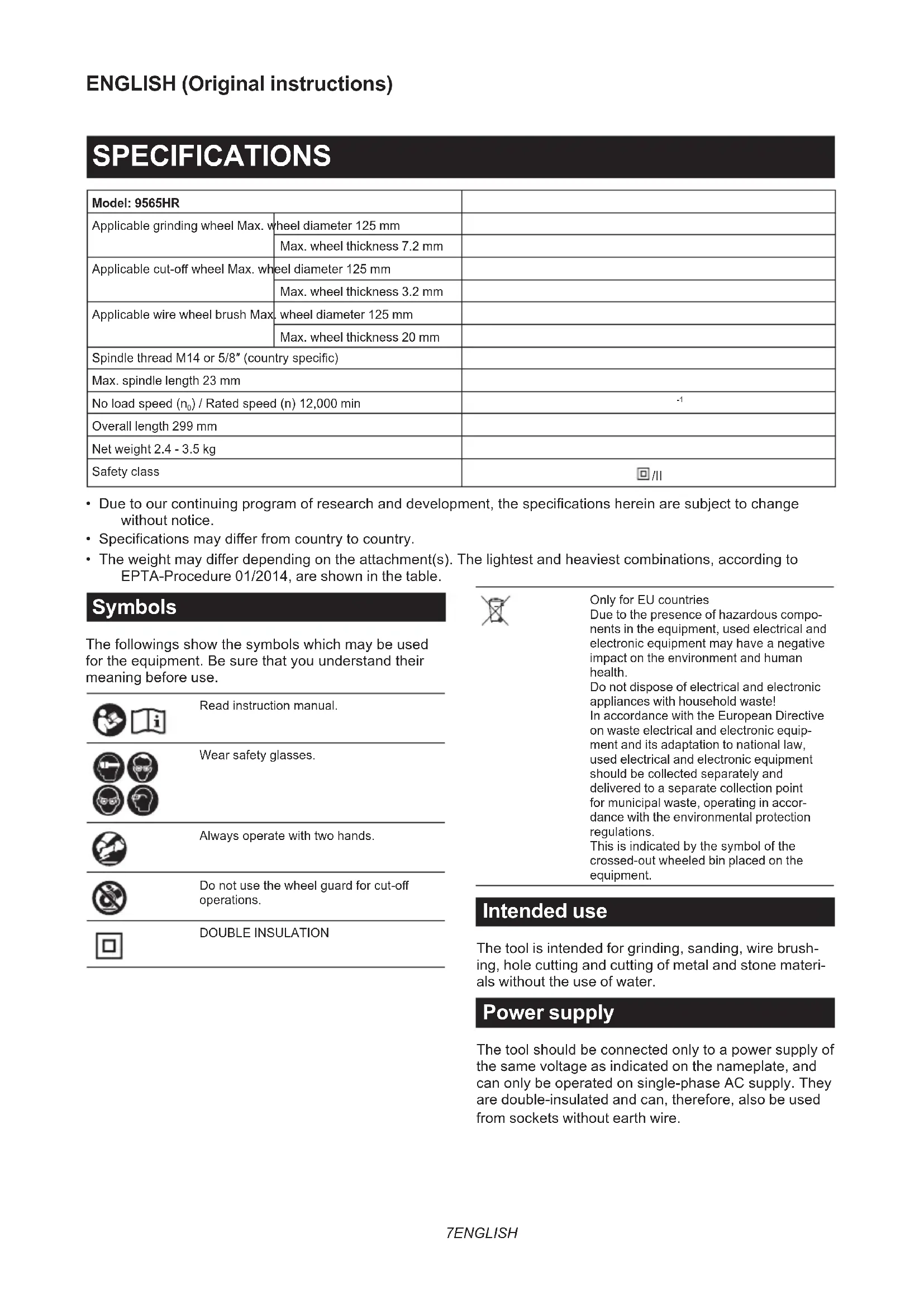
Fig.337 ENGLISH ENGLISH (Original instructions) SPECIFICATIONS Model: 9565HR Applicable grinding wheel Max. wheel diameter 125 mm Max. wheel thickness 7.2 mm Applicable cut-o wheel Max. wheel diameter 125 mm Max. wheel thickness 3.2 mm Applicable wire wheel brush Max. wheel diameter 125 mm Max. wheel thickness 20 mm Spindle thread M14 or 5/8″ (country specic) Max. spindle length 23 mm No load speed (n
- Due to our continuing program of research and development, the specications herein are subject to change without notice.
- Specications may dier from country to country.
- The weight may dier depending on the attachment(s). The lightest and heaviest combinations, according to EPTA-Procedure 01/2014, are shown in the table. Symbols The followings show the symbols which may be used for the equipment. Be sure that you understand their meaning before use. Read instruction manual. Wear safety glasses. Always operate with two hands. Do not use the wheel guard for cut-o operations. DOUBLE INSULATION Only for EU countries Due to the presence of hazardous compo- nents in the equipment, used electrical and electronic equipment may have a negative impact on the environment and human health. Do not dispose of electrical and electronic appliances with household waste! In accordance with the European Directive on waste electrical and electronic equip- ment and its adaptation to national law, used electrical and electronic equipment should be collected separately and delivered to a separate collection point for municipal waste, operating in accor- dance with the environmental protection regulations. This is indicated by the symbol of the crossed-out wheeled bin placed on the equipment. Intended use The tool is intended for grinding, sanding, wire brush- ing, hole cutting and cutting of metal and stone materi- als without the use of water. Power supply The tool should be connected only to a power supply of the same voltage as indicated on the nameplate, and can only be operated on single-phase AC supply. They are double-insulated and can, therefore, also be used from sockets without earth wire.8 ENGLISH Noise The typical A-weighted noise level determined according to EN62841-2-3: Model Sound pressure level (L
) : (dB(A)) Uncertainty (K) : (dB(A)) 9565HR 87 95 3 NOTE: The declared noise emission value(s) has been measured in accordance with a standard test method and may be used for comparing one tool with another. NOTE: The declared noise emission value(s) may also be used in a preliminary assessment of exposure.
WARNING: Wear ear protection.
WARNING: The noise emission during actual use of the power tool can dier from the declared val-
ue(s) depending on the ways in which the tool is used especially what kind of workpiece is processed.
WARNING: Be sure to identify safety measures to protect the operator that are based on an estimation
of exposure in the actual conditions of use (taking account of all parts of the operating cycle such as the times when the tool is switched o and when it is running idle in addition to the trigger time).
WARNING: Grinding thin sheets of metal or other easily vibrating structures with a large surface can
result in a total noise emission much higher (up to 15 dB) than the declared noise emission values. Set heavy exible damping mats or such to those workpieces to prevent them from emitting sound. Take the increased noise emission into consideration for both the risk assessment of noise exposure and selecting adequate hearing protection. Vibration The vibration total value (tri-axial vector sum) determined according to EN62841-2-3: Work mode: surface grinding with normal side grip Model Vibration emission (a
9565HR 9.0 1.5 Work mode: surface grinding with anti vibration side grip Model Vibration emission (a
9565HR 7.5 1.5 Work mode: disc sanding with normal side grip Model Vibration emission (a
or less 1.5 Work mode: disc sanding with anti vibration side grip Model Vibration emission (a
or less 1.5 NOTE: The declared vibration total value(s) has been measured in accordance with a standard test method and may be used for comparing one tool with another. NOTE: The declared vibration total value(s) may also be used in a preliminary assessment of exposure.
WARNING: The vibration emission during actual use of the power tool can dier from the declared
value(s) depending on the ways in which the tool is used especially what kind of workpiece is processed.
WARNING: Be sure to identify safety measures to protect the operator that are based on an estimation
of exposure in the actual conditions of use (taking account of all parts of the operating cycle such as the times when the tool is switched o and when it is running idle in addition to the trigger time).
WARNING: The declared vibration emission value is used for main applications of the power tool. However if
the power tool is used for other applications, the vibration emission value may be dierent.9 ENGLISH EC Declaration of Conformity For European countries only The EC declaration of conformity is included as Annex A to this instruction manual. SAFETY WARNINGS General power tool safety warnings WARNING Read all safety warnings, instruc- tions, illustrations and specications provided with this power tool. Failure to follow all instructions listed below may result in electric shock, re and/or serious injury. Save all warnings and instruc- tions for future reference. The term "power tool" in the warnings refers to your mains-operated (corded) power tool or battery-operated (cordless) power tool. Grinder safety warnings Safety warnings common for grinding, sanding, wire brushing, or cutting-o operations:
1. This power tool is intended to function as a
grinder, sander, wire brush, hole cutter or cut- o tool. Read all safety warnings, instructions, illustrations and specications provided with this power tool. Failure to follow all instructions listed below may result in electric shock, re and/ or serious injury.
2. Operations such as polishing are not to be
performed with this power tool. Operations for which the power tool was not designed may create a hazard and cause personal injury.
3. Do not convert this power tool to operate in
a way which is not specically designed and specied by the tool manufacturer. Such a con- version may result in a loss of control and cause serious personal injury.
4. Do not use accessories which are not spe-
cically designed and specied by the tool manufacturer. Just because the accessory can be attached to your power tool, it does not assure safe operation.
5. The rated speed of the accessory must be at
least equal to the maximum speed marked on the power tool. Accessories running faster than their rated speed can break and y apart.
6. The outside diameter and the thickness of your
accessory must be within the capacity rating of your power tool. Incorrectly sized accessories cannot be adequately guarded or controlled.
7. The dimensions of the accessory mounting
must t the dimensions of the mounting hard- ware of the power tool. Accessories that do not match the mounting hardware of the power tool will run out of balance, vibrate excessively and may cause loss of control.
8. Do not use a damaged accessory. Before each
use inspect the accessory such as abrasive wheels for chips and cracks, backing pad for cracks, tear or excess wear, wire brush for loose or cracked wires. If power tool or acces- sory is dropped, inspect for damage or install an undamaged accessory. After inspecting and installing an accessory, position yourself and bystanders away from the plane of the rotating accessory and run the power tool at maximum no-load speed for one minute. Damaged acces- sories will normally break apart during this test time.
9. Wear personal protective equipment.
Depending on application, use face shield, safety goggles or safety glasses. As appro- priate, wear dust mask, hearing protectors, gloves and workshop apron capable of stop- ping small abrasive or workpiece fragments. The eye protection must be capable of stopping ying debris generated by various applications. The dust mask or respirator must be capable of ltrating particles generated by the particular application. Prolonged exposure to high intensity noise may cause hearing loss.
10. Keep bystanders a safe distance away from
work area. Anyone entering the work area must wear personal protective equipment. Fragments of workpiece or of a broken accessory may y away and cause injury beyond immediate area of operation.
11. Hold the power tool by insulated gripping
surfaces only, when performing an operation where the cutting accessory may contact hid- den wiring or its own cord. Cutting accessory contacting a "live" wire may make exposed metal parts of the power tool "live" and could give the operator an electric shock.
12. Position the cord clear of the spinning acces-
sory. If you lose control, the cord may be cut or snagged and your hand or arm may be pulled into the spinning accessory.
13. Never lay the power tool down until the acces-
sory has come to a complete stop. The spinning accessory may grab the surface and pull the power tool out of your control.
14. Do not run the power tool while carrying it at
your side. Accidental contact with the spinning accessory could snag your clothing, pulling the accessory into your body.
15. Regularly clean the power tool’s air vents. The
motor’s fan will draw the dust inside the housing and excessive accumulation of powdered metal may cause electrical hazards.
16. Do not operate the power tool near ammable
materials. Sparks could ignite these materials.
17. Do not use accessories that require liquid
coolants. Using water or other liquid coolants may result in electrocution or shock.10 ENGLISH Kickback and related warnings: Kickback is a sudden reaction to a pinched or snagged rotating wheel, backing pad, brush or any other acces- sory. Pinching or snagging causes rapid stalling of the rotating accessory which in turn causes the uncon- trolled power tool to be forced in the direction opposite of the accessory’s rotation at the point of the binding. For example, if an abrasive wheel is snagged or pinched by the workpiece, the edge of the wheel that is entering into the pinch point can dig into the surface of the material causing the wheel to climb out or kick out. The wheel may either jump toward or away from the operator, depending on direction of the wheel’s move- ment at the point of pinching. Abrasive wheels may also break under these conditions. Kickback is the result of power tool misuse and/or incorrect operating procedures or conditions and can be avoided by taking proper precautions as given below.
Maintain a rm grip with both hands on the power tool and position your body and arms to allow you to resist kickback forces. Always use auxiliary handle, if provided, for maximum control over kickback or torque reaction during start-up. The operator can control torque reactions or kickback forces, if proper precautions are taken.
2. Never place your hand near the rotating acces-
sory. Accessory may kickback over your hand.
3. Do not position your body in the area where
power tool will move if kickback occurs. Kickback will propel the tool in direction opposite to the wheel’s movement at the point of snagging.
4. Use special care when working corners, sharp
edges, etc. Avoid bouncing and snagging the accessory. Corners, sharp edges or bouncing have a tendency to snag the rotating accessory and cause loss of control or kickback.
Do not attach a saw chain woodcarving blade, segmented diamond wheel with a peripheral gap greater than 10 mm or toothed saw blade. Such blades create frequent kickback and loss of control. Safety warnings specic for grinding and cutting-o operations:
1. Use only wheel types that are specied
for your power tool and the specic guard designed for the selected wheel. Wheels for which the power tool was not designed cannot be adequately guarded and are unsafe.
2. The grinding surface of centre depressed
wheels must be mounted below the plane of the guard lip. An improperly mounted wheel that projects through the plane of the guard lip cannot be adequately protected.
3. The guard must be securely attached to the
power tool and positioned for maximum safety, so the least amount of wheel is exposed towards the operator. The guard helps to protect the operator from broken wheel fragments, acci- dental contact with wheel and sparks that could ignite clothing.
4. Wheels must be used only for specied appli-
cations. For example: do not grind with the side of cut-o wheel. Abrasive cut-o wheels are intended for peripheral grinding, side forces applied to these wheels may cause them to shatter.
5. Always use undamaged wheel anges that are
of correct size and shape for your selected wheel. Proper wheel anges support the wheel thus reducing the possibility of wheel breakage. Flanges for cut-o wheels may be dierent from grinding wheel anges.
6. Do not use worn down wheels from larger
power tools. A wheel intended for larger power tool is not suitable for the higher speed of a smaller tool and may burst.
7. When using dual purpose wheels always use
the correct guard for the application being performed. Failure to use the correct guard may not provide the desired level of guarding, which could lead to serious injury. Additional safety warnings specic for cutting-o operations:
1. Do not “jam” the cut-o wheel or apply exces-
sive pressure. Do not attempt to make an excessive depth of cut. Overstressing the wheel increases the loading and susceptibility to twisting or binding of the wheel in the cut and the possibil- ity of kickback or wheel breakage.
2. Do not position your body in line with and
behind the rotating wheel. When the wheel, at the point of operation, is moving away from your body, the possible kickback may propel the spin- ning wheel and the power tool directly at you.
3. When the wheel is binding or when interrupt-
ing a cut for any reason, switch o the power tool and hold it motionless until the wheel comes to a complete stop. Never attempt to remove the cut-o wheel from the cut while the wheel is in motion otherwise kickback may occur. Investigate and take corrective action to eliminate the cause of wheel binding.
Do not restart the cutting operation in the work- piece. Let the wheel reach full speed and carefully re-enter the cut. The wheel may bind, walk up or kickback if the power tool is restarted in the workpiece.
5. Support panels or any oversized workpiece to
minimize the risk of wheel pinching and kick- back. Large workpieces tend to sag under their own weight. Supports must be placed under the workpiece near the line of cut and near the edge of the workpiece on both sides of the wheel.
6. Use extra caution when making a “pocket cut”
into existing walls or other blind areas. The protruding wheel may cut gas or water pipes, elec- trical wiring or objects that can cause kickback.
7. Do not attempt to do curved cutting.
Overstressing the wheel increases the loading and susceptibility to twisting or binding of the wheel in the cut and the possibility of kickback or wheel breakage, which can lead to serious injury.
8. Before using a segmented diamond wheel,
make sure that the diamond wheel has the peripheral gap between segments of 10 mm or less, only with a negative rake angle. Safety warnings specic for sanding operations:
1. Use proper sized sanding disc paper. Follow
manufacturers recommendations, when selecting sanding paper. Larger sanding paper extending too far beyond the sanding pad pres- ents a laceration hazard and may cause snagging, tearing of the disc or kickback.11 ENGLISH Safety warnings specic for wire brushing operations:
1. Be aware that wire bristles are thrown by the
brush even during ordinary operation. Do not overstress the wires by applying excessive load to the brush. The wire bristles can easily penetrate light clothing and/or skin.
2. If the use of a guard is specied for wire
brushing, do not allow any interference of the wire wheel or brush with the guard. Wire wheel or brush may expand in diameter due to work load and centrifugal forces. Additional Safety Warnings:
1. When using depressed centre grinding wheels,
be sure to use only berglass-reinforced wheels.
2. NEVER USE Stone Cup type wheels with this
grinder. This grinder is not designed for these types of wheels and the use of such a product may result in serious personal injury.
3. Be careful not to damage the spindle, the
ange (especially the installing surface) or the lock nut. Damage to these parts could result in wheel breakage.
4. Make sure the wheel is not contacting the
workpiece before the switch is turned on.
5. Before using the tool on an actual workpiece,
let it run for a while. Watch for vibration or wobbling that could indicate poor installation or a poorly balanced wheel.
6. Use the specied surface of the wheel to per-
7. Do not leave the tool running. Operate the tool
only when hand-held.
8. Do not touch the workpiece immediately after
operation; it may be extremely hot and could burn your skin.
9. Do not touch accessories immediately after
operation; it may be extremely hot and could burn your skin.
10. Observe the instructions of the manufacturer
for correct mounting and use of wheels. Handle and store wheels with care.
11. Do not use separate reducing bushings or
adaptors to adapt large hole abrasive wheels.
12. Use only anges specied for this tool.
13. For tools intended to be tted with threaded
hole wheel, ensure that the thread in the wheel is long enough to accept the spindle length.
14. Check that the workpiece is properly
15. Pay attention that the wheel continues to
rotate after the tool is switched o.
16. If working place is extremely hot and humid,
or badly polluted by conductive dust, use a short-circuit breaker (30 mA) to assure opera- tor safety.
18. When use cut-o wheel, always work with
the dust collecting wheel guard if required by domestic regulation.
19. Cutting discs must not be subjected to any
20. Do not use cloth work gloves during operation.
Fibers from cloth gloves may enter the tool, which causes tool breakage.
21. Before operation, make sure that there is no
buried object such as electric pipe, water pipe or gas pipe in the workpiece. Otherwise, it may cause an electric shock, electrical leakage or gas leak.
22. If a blotter is attached to the wheel, do not
remove it. The diameter of the blotter must be larger than the lock nut, outer ange, and inner ange.
23. Before installing a grinding wheel, always
check that the blotter part does not have any abnormalities such as chips or cracks.
24. Tighten the lock nut properly. Overtightening
the wheel can cause breakage and insucient tightening can cause uttering. SAVE THESE INSTRUCTIONS.
WARNING: DO NOT let comfort or familiarity
with product (gained from repeated use) replace strict adherence to safety rules for the subject product. MISUSE or failure to follow the safety rules stated in this instruction manual may cause serious personal injury. FUNCTIONAL DESCRIPTION CAUTION: Always be sure that the tool is switched o and unplugged before adjusting or checking function on the tool. Indication lamp ► Fig.1: 1. Indication lamp The indication lamp lights up green when the tool is plugged. If the indication lamp does not light up, the mains cord or the controller may be defective. The indication lamp is lit but the tool does not start even if the tool is switched on, the carbon brushes may be worn out, or the controller, the motor or the ON/OFF switch may be defective. Shaft lock
WARNING: Never actuate the shaft lock when
the spindle is moving. It may cause serious injury or the tool damage. Press the shaft lock to prevent spindle rotation when installing or removing accessories. ► Fig.2: 1. Shaft lock12 ENGLISH Switch action CAUTION: Before plugging in the tool, always check to see that the slide switch actuates prop- erly and returns to the "OFF" position when the rear end of the slide switch is depressed. CAUTION: Switch can be locked in the "ON" position for ease of operator comfort during extended use. Apply caution when locking tool in the "ON" position and maintain rm grasp on tool. To start the tool, press down the rear end of the slide switch and then slide it toward the “I (ON)” position. For continuous operation, press down the front end of the slide switch to lock it. ► Fig.3: 1. Slide switch To stop the tool, press down the rear end of the slide switch so that it returns to the “O (OFF)” position. ► Fig.4: 1. Slide switch Accidental re-start preventive function When plugging in the tool while the switch is ON, the tool does not start. At this time, the indication lamp blinks in red and shows that the accidental re-start preventive function works. To start the tool, turn o the switch, and turn it on again. Soft start feature Soft start feature reduces starting reaction. ASSEMBLY CAUTION: Always be sure that the tool is switched o and unplugged before carrying out any work on the tool. Installing side grip (handle) CAUTION: Always be sure that the side grip is installed securely before operation. Screw the side grip securely on the position of the tool as shown in the gure. ► Fig.5 Installing or removing wheel guard (For depressed center wheel, ap disc, ex wheel, wire wheel brush / abrasive cut-o wheel, diamond wheel)
When using a depressed center wheel, ap disc, ex wheel or wire wheel brush, the wheel guard must be tted on the tool so that the closed side of the guard always points toward the operator.
WARNING: When using an abrasive cut-o
/ diamond wheel, be sure to use only the special wheel guard designed for use with cut-o wheels. For tool with locking screw type wheel guard Mount the wheel guard with the protrusions on the wheel guard band aligned with the notches on the bearing box. Then rotate the wheel guard to such an angle that it can protect the opera- tor according to work. Be sure to tighten the screw securely. To remove wheel guard, follow the installation proce- dure in reverse. ► Fig.6: 1. Wheel guard 2. Bearing box 3. Screw For tool with clamp lever type wheel guard Loosen the screw, and then pull the lever in the direction of the arrow. Mount the wheel guard with the protrusions on the wheel guard band aligned with the notches on the bearing box. Then rotate the wheel guard to such an angle that it can protect the operator according to work. ► Fig.7:
1. Wheel guard 2. Bearing box 3. Screw 4. Lever
Pull the lever in direction of the arrow. Then tighten the wheel guard with fastening the screw. Be sure to tighten the screw securely. The setting angle of the wheel guard can be adjusted with the lever. ► Fig.8: 1. Screw 2. Lever To remove wheel guard, follow the installation proce- dure in reverse. Clip-on cutting wheel guard attachment Optional accessory NOTE: For cutting-o operations, a clip-on cutting wheel guard attachment can be used with the wheel guard (for grinding wheel). Not available in some countries. ► Fig.9 Installing or removing depressed center wheel or ap disc Optional accessory
WARNING: When using a depressed center
wheel or ap disc, the wheel guard must be tted on the tool so that the closed side of the guard always points toward the operator.
WARNING: Make sure that the mounting part
of the inner ange ts into the inner diameter of the depressed center wheel / ap disc perfectly. Mounting the inner ange on the wrong side may result in the dangerous vibration. Mount the inner ange onto the spindle. Make sure to t the dented part of the inner ange onto the straight part at the bottom of the spindle. Fit the depressed center wheel / ap disc on the inner ange and screw the lock nut onto the spindle. ► Fig.10: 1. Lock nut 2. Depressed center wheel
3. Inner ange 4. Mounting part
To tighten the lock nut, press the shaft lock rmly so that the spindle cannot revolve, then use the lock nut wrench and securely tighten clockwise. ► Fig.11: 1. Lock nut wrench 2. Shaft lock To remove the wheel, follow the installation procedure in reverse.13 ENGLISH Installing or removing ex wheel Optional accessory
WARNING: Always use supplied guard when
ex wheel is on the tool. Wheel can shatter during use and guard helps to reduce chances of personal injury. ► Fig.12: 1. Lock nut 2. Flex wheel 3. Back up pad
Follow instructions for depressed center wheel but also use back up pad over wheel. Installing or removing abrasive disc Optional accessory ► Fig.13: 1. Sanding lock nut 2. Abrasive disc
1. Mount the rubber pad onto the spindle.
2. Fit the disc on the rubber pad and screw the sand-
Hold the spindle with the shaft lock, and securely tighten the sanding lock nut clockwise with the lock nut wrench. To remove the disc, follow the installation procedure in reverse. NOTE: Use sander accessories specied in this man- ual. These must be purchased separately. Super ange Optional accessory Super ange is a special accessory for model which is NOT equipped with a brake function. Models with the letter F are standard-equipped with Super ange. Only 1/3 of eorts needed to undo lock nut, compared with conventional type. Installing or removing Ezynut Optional accessory Only for tools with M14 spindle thread. CAUTION: Do not use Ezynut with Super Flange. Those anges are so thick that the entire thread cannot be retained by the spindle. Mount inner ange, abrasive wheel and Ezynut onto the spindle so that Makita Logo on Ezynut faces outside. ► Fig.14: 1. Ezynut 2. Abrasive wheel 3. Inner ange
Press shaft lock rmly and tighten Ezynut by turning the abrasive wheel clockwise as far as it turns. ► Fig.15: 1. Shaft lock To loosen the Ezynut, turn the outside ring of Ezynut counterclockwise. NOTE: Ezynut can be loosened by hand as long as the arrow points the notch. Otherwise a lock nut wrench is required to loosen it. Insert one pin of the wrench into a hole and turn Ezynut counterclockwise. ► Fig.16: 1. Arrow 2. Notch ► Fig.17 Installing abrasive cut-o / diamond wheel Optional accessory
WARNING: When using an abrasive cut-o
/ diamond wheel, be sure to use only the special wheel guard designed for use with cut-o wheels.
WARNING: NEVER use cut-o wheel for side
grinding. ► Fig.18: 1. Lock nut 2. Abrasive cut-o wheel / dia- mond wheel 3. Inner ange 4. Wheel guard for abrasive cut-o wheel / diamond wheel As for the installation, follow the instructions for depressed center wheel. The direction for mounting the lock nut and the inner ange varies by wheel type and thickness. Refer to the following gures. When installing the abrasive cut-o wheel: ► Fig.19: 1. Lock nut 2. Abrasive cut-o wheel (Thinner than 4 mm (5/32")) 3. Abrasive cut- o wheel (4 mm (5/32") or thicker) 4. Inner ange When installing the diamond wheel: ► Fig.20: 1. Lock nut 2. Diamond wheel (Thinner than 4 mm (5/32″)) 3. Diamond wheel (4 mm (5/32″) or thicker) 4. Inner ange Installing wire cup brush Optional accessory CAUTION: Do not use brush that is damaged, or which is out of balance. Use of damaged brush could increase potential for injury from contact with broken brush wires. Place the tool upside down to allow easy access to the spindle. Remove any accessories on spindle. Thread wire cup brush onto spindle and tighten with supplied wrench. ► Fig.21: 1. Wire cup brush Installing wire wheel brush Optional accessory CAUTION: Do not use wire wheel brush that is damaged, or which is out of balance. Use of damaged wire wheel brush could increase potential for injury from contact with broken wires. CAUTION: ALWAYS use guard with wire wheel brushes, assuring diameter of wheel ts inside guard. Wheel can shatter during use and guard helps to reduce chances of personal injury. Place the tool upside down to allow easy access to the spindle. Remove any accessories on spindle. Thread wire wheel brush onto spindle and tighten with the wrenches. ► Fig.22: 1. Wire wheel brush14 ENGLISH Installing hole cutter Optional accessory Place the tool upside down to allow easy access to the spindle. Remove any accessories on the spindle. Thread the hole cutter onto the spindle, and tighten it with the sup- plied wrench. ► Fig.23: 1. Hole cutter Installing dust collecting wheel guard for grinding Optional accessory With optional accessories, you can use this tool for planing concrete surface. CAUTION: Dust collecting wheel guard for grinding is only for use in planing concrete sur- face with a cup-type diamond wheel. Do not use this guard with any other cutting accessory or for any other purpose. CAUTION: Before operation, make sure that a vacuum cleaner is connected to the tool and turned on. Place the tool upside down and install the dust collect- ing wheel guard. Mount the inner ange onto the spindle. Fit the cup-type diamond wheel on the inner ange and tighten the lock nut onto the spindle. ► Fig.24: 1. Lock nut 2. Cup-type diamond wheel
3. Hubbed cup-type diamond wheel 4. Inner
ange 5. Dust collecting wheel guard
NOTE: For information how to install the dust col- lecting wheel guard, refer to the manual of the dust collecting wheel guard. Installing dust collecting wheel guard for cutting-o Optional accessory With optional accessories, you can use this tool for cutting stone materials. ► Fig.25 NOTE: For information how to install the dust col- lecting wheel guard, refer to the manual of the dust collecting wheel guard. Installing or removing dust cover attachment Optional accessory CAUTION: Always be sure that the tool is switched o and unplugged before installing or removing the dust cover attachment. Failure to do so causes damage to the tool or a personal injury. Install the dust cover attachment to each specied position. For details, refer to the instruction manual of the dust cover attachment. NOTICE: Clean out the dust cover attachment when it is clogged with dust or foreign matters. Continuing operation with a clogged dust cover attachment will damage the tool. OPERATION
WARNING: It should never be necessary to
force the tool. The weight of the tool applies ade- quate pressure. Forcing and excessive pressure could cause dangerous wheel breakage.
WARNING: ALWAYS replace wheel if tool is
dropped while grinding.
WARNING: NEVER hit the workpiece with the
WARNING: Avoid bouncing and snagging
the wheel, especially when working corners, sharp edges etc. This can cause loss of control and kickback.
WARNING: NEVER use tool with wood cutting
blades and other saw blades. Such blades when used on a grinder frequently kick and cause loss of control leading to personal injury. CAUTION: Never switch on the tool when it is in contact with the workpiece, it may cause an injury to operator. CAUTION: Always wear safety goggles or a face shield during operation. CAUTION: After operation, always switch o the tool and wait until the wheel has come to a complete stop before putting the tool down. CAUTION: ALWAYS hold the tool rmly with one hand on housing and the other on the side grip (handle). NOTE: A dual purpose wheel can be used for both grinding and cutting-o operations. Refer to the "Grinding and sanding operation" for grinding operation, and refer to the "Operation with abrasive cut-o / diamond wheel" for cutting-o operation.15 ENGLISH Grinding and sanding operation ► Fig.26 Turn the tool on and then apply the wheel or disc to the workpiece. In general, keep the edge of the wheel or disc at an angle of about 15° to the workpiece surface. During the break-in period with a new wheel, do not work the grinder in forward direction or it may cut into the workpiece. Once the edge of the wheel has been rounded o by use, the wheel may be worked in both forward and backward direction. Usage example: operation with cup-type diamond wheel ► Fig.27 Keep the tool horizontally and apply the entire cup-type diamond wheel to the workpiece surface. Operation with abrasive cut-o / diamond wheel Optional accessory
WARNING: Do not "jam" the wheel or apply
excessive pressure. Do not attempt to make an excessive depth of cut. Overstressing the wheel increases the loading and susceptibility to twisting or binding of the wheel in the cut and the possibility of kickback, wheel breakage and overheating of the motor may occur.
WARNING: Do not start the cutting operation
in the workpiece. Let the wheel reach full speed and carefully enter into the cut moving the tool forward over the workpiece surface. The wheel may bind, walk up or kickback if the power tool is started in the workpiece.
WARNING: During cutting operations, never
change the angle of the wheel. Placing side pres- sure on the cut-o wheel (as in grinding) will cause the wheel to crack and break, causing serious per- sonal injury.
WARNING: A diamond wheel shall be oper-
ated perpendicular to the material being cut. Usage example: operation with abrasive cut-o wheel ► Fig.28 Usage example: operation with diamond wheel ► Fig.29 Operation with wire cup brush Optional accessory CAUTION: Check operation of brush by run- ning tool with no load, insuring that no one is in front of or in line with brush. NOTICE: Avoid applying too much pressure which causes over bending of wires when using the wire cup brush. It may lead to premature breakage. Usage example: operation with wire cup brush ► Fig.30 Operation with wire wheel brush Optional accessory CAUTION: Check operation of wire wheel brush by running tool with no load, insuring that no one is in front of or in line with the wire wheel brush. NOTICE: Avoid applying too much pressure which causes over bending of wires when using wire wheel brush. It may lead to premature breakage. Usage example: operation with wire wheel brush ► Fig.31 Operation with hole cutter Optional accessory CAUTION: Check operation of the hole cutter by running the tool with no load, insuring that no one is in front of the hole cutter. NOTICE: Do not tilt the tool during operation. It may lead to premature breakage. Usage example: operation with hole cutter ► Fig.32 MAINTENANCE CAUTION: Always be sure that the tool is switched o and unplugged before attempting to perform inspection or maintenance. NOTICE: Never use gasoline, benzine, thinner, alcohol or the like. Discoloration, deformation or cracks may result. To maintain product SAFETY and RELIABILITY, repairs, carbon brush inspection and replacement, any other maintenance or adjustment should be performed by Makita Authorized or Factory Service Centers, always using Makita replacement parts. Air vent cleaning The tool and its air vents have to be kept clean. Regularly clean the tool's air vents or whenever the vents start to become obstructed. ► Fig.33: 1. Exhaust vent 2. Inhalation vent16 ENGLISH
COMBINATION OF APPLICATIONS AND
ACCESSORIES Optional accessory CAUTION: Using the tool with incorrect guards can cause risks as follows.
- When using a cut-o wheel guard for facial grinding, the wheel guard may interfere with the work- piece causing poor control.
- When using a grinding wheel guard for cutting-o operations with bonded abrasive wheels and dia- mond wheels, there is an increased risk of exposure to rotating wheels, emitted sparks and particles, as well as exposure to wheel fragments in the event of wheel burst.
- When using a cut-o wheel guard or grinding wheel guard for facial operations with cup-type dia- mond wheels, the wheel guard may interfere with the workpiece causing poor control.
- When using a cut-o wheel guard or grinding wheel guard with a wheel-type wire brush with a thick- ness greater than the maximum thickness as specied in "SPECIFICATIONS", the wires may catch on the guard leading to breaking of wires.
- Use of dust collecting wheel guards for cutting-o and facial operations in concrete or masonry reduces a risk of exposure to dust.
- When using dual purpose (combined grinding and cutting-o abrasive) ange mounted wheels, only use a cut-o wheel guard.
2 - Wheel guard (for grinding wheel)
3 - Inner ange / Super ange *1
4 Grinding / Sanding Depressed center wheel / Flap disc
8 Grinding Flex wheel
10 Sanding Abrasive disc
11 - Sanding lock nut
12 Wire brushing Wire wheel brush17 ENGLISH - Application 125 mm model 13 Wire brushing Wire cup brush 14 Hole cutting Hole cutter
15 - Wheel guard (for cut-o wheel)
16 Cutting-o Abrasive cut-o wheel / Diamond wheel 17 Grinding / Cutting-o Dual purpose wheel
18 - Clip-on cutting wheel guard attachment *3
19 - Dust collecting wheel guard for cut-
ting-o *4 20 Cutting-o Diamond wheel
21 - Dust collecting wheel guard for grinding *5
22 Grinding Cup-type diamond wheel *5 - - Lock nut wrench - - Dust cover attachment NOTE: *1 Do not use Super ange and Ezynut together. NOTE: *2 Only for tools with M14 spindle thread. NOTE: *3 Clip-on cutting wheel guard attachment is not available in some countries. For more details, refer to the instruction manual of the clip-on cutting wheel guard attachment. NOTE: *4 For more details, refer to each instruction manual of the guard. NOTE: *5 For more details, refer to each instruction manual of the guard. OPTIONAL ACCESSORIES CAUTION: These accessories or attachments are recommended for use with your Makita tool specied in this manual. The use of any other accessories or attachments might present a risk of injury to persons. Only use accessory or attachment for its stated purpose. If you need any assistance for more details regard- ing these accessories, ask your local Makita Service Center.
- Accessories listed in "COMBINATION OF
APPLICATIONS AND ACCESSORIES"
8 Meulage Meule exible