GA4030R - Grinder MAKITA - Free user manual and instructions
Find the device manual for free GA4030R MAKITA in PDF.
Download the instructions for your Grinder in PDF format for free! Find your manual GA4030R - MAKITA and take your electronic device back in hand. On this page are published all the documents necessary for the use of your device. GA4030R by MAKITA.
USER MANUAL GA4030R MAKITA
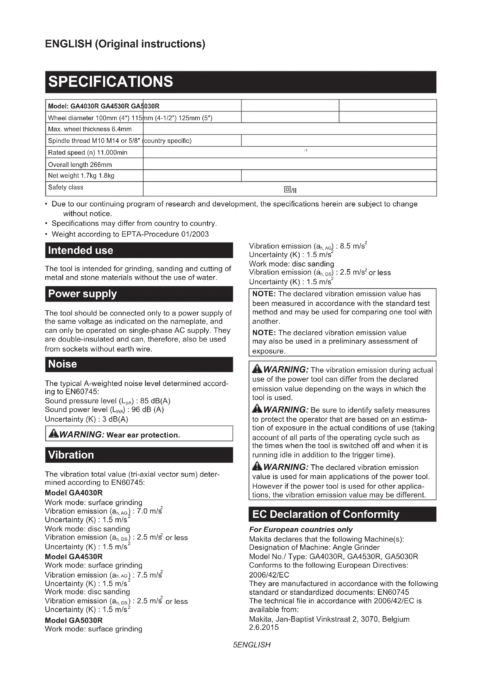
Fig.20 45 ENGLISH ENGLISH (Original instructions) SPECIFICATIONS Model: GA4030R GA4530R GA5030R Wheel diameter 100mm (4″) 115mm (4-1/2″) 125mm (5″) Max. wheel thickness 6.4mm Spindle thread M10 M14 or 5/8″ (country specic) Rated speed (n) 11,000min
- Due to our continuing program of research and development, the specications herein are subject to change without notice.
- Specications may differ from country to country.
- Weight according to EPTA-Procedure 01/2003 Intended use The tool is intended for grinding, sanding and cutting of metal and stone materials without the use of water. Power supply The tool should be connected only to a power supply of the same voltage as indicated on the nameplate, and can only be operated on single-phase AC supply. They are double-insulated and can, therefore, also be used from sockets without earth wire. Noise The typical A-weighted noise level determined accord- ing to EN60745: Sound pressure level (L
WARNING: Wear ear protection.
Vibration The vibration total value (tri-axial vector sum) deter- mined according to EN60745: Model GA4030R Work mode: surface grinding Vibration emission (a h, AG ) : 7.0 m/s
Work mode: disc sanding Vibration emission (a h, DS ) : 2.5 m/s
Work mode: disc sanding Vibration emission (a h, DS ) : 2.5 m/s
Work mode: disc sanding Vibration emission (a h, DS ) : 2.5 m/s
NOTE: The declared vibration emission value has been measured in accordance with the standard test method and may be used for comparing one tool with another. NOTE: The declared vibration emission value may also be used in a preliminary assessment of exposure.
WARNING: The vibration emission during actual
use of the power tool can differ from the declared emission value depending on the ways in which the tool is used.
WARNING: Be sure to identify safety measures
to protect the operator that are based on an estima- tion of exposure in the actual conditions of use (taking account of all parts of the operating cycle such as the times when the tool is switched off and when it is running idle in addition to the trigger time).
WARNING: The declared vibration emission
value is used for main applications of the power tool. However if the power tool is used for other applica- tions, the vibration emission value may be different. EC Declaration of Conformity For European countries only Makita declares that the following Machine(s): Designation of Machine: Angle Grinder Model No./ Type: GA4030R, GA4530R, GA5030R Conforms to the following European Directives: 2006/42/EC They are manufactured in accordance with the following standard or standardized documents: EN60745 The technical le in accordance with 2006/42/EC is available from: Makita, Jan-Baptist Vinkstraat 2, 3070, Belgium
WARNING: Read all safety warnings and
all instructions. Failure to follow the warnings and instructions may result in electric shock, re and/or serious injury. Save all warnings and instruc- tions for future reference. The term "power tool" in the warnings refers to your mains-operated (corded) power tool or battery-operated (cordless) power tool. Grinder safety warnings Safety Warnings Common for Grinding, Sanding, Wire Brushing, or Abrasive Cutting-Off Operations:
1. This power tool is intended to function as a
grinder, sander, wire brush or cut-off tool. Read all safety warnings, instructions, illus- trations and specications provided with this power tool. Failure to follow all instructions listed below may result in electric shock, re and/or serious injury.
2. Operations such as polishing are not rec-
ommended to be performed with this power tool. Operations for which the power tool was not designed may create a hazard and cause per- sonal injury.
3. Do not use accessories which are not speci-
cally designed and recommended by the tool manufacturer. Just because the accessory can be attached to your power tool, it does not assure safe operation.
4. The rated speed of the accessory must be at
least equal to the maximum speed marked on the power tool. Accessories running faster than their rated speed can break and y apart.
5. The outside diameter and the thickness of your
accessory must be within the capacity rating of your power tool. Incorrectly sized accessories cannot be adequately guarded or controlled.
6. Threaded mounting of accessories must
match the grinder spindle thread. For acces- sories mounted by anges, the arbour hole of the accessory must t the locating diameter of the ange. Accessories that do not match the mounting hardware of the power tool will run out of balance, vibrate excessively and may cause loss of control.
7. Do not use a damaged accessory. Before each
use inspect the accessory such as abrasive wheels for chips and cracks, backing pad for cracks, tear or excess wear, wire brush for loose or cracked wires. If power tool or acces- sory is dropped, inspect for damage or install an undamaged accessory. After inspecting and installing an accessory, position yourself and bystanders away from the plane of the rotating accessory and run the power tool at maximum no-load speed for one minute. Damaged acces- sories will normally break apart during this test time.
8. Wear personal protective equipment.
Depending on application, use face shield, safety goggles or safety glasses. As appro- priate, wear dust mask, hearing protectors, gloves and workshop apron capable of stop- ping small abrasive or workpiece fragments. The eye protection must be capable of stopping ying debris generated by various operations. The dust mask or respirator must be capable of ltrating particles generated by your operation. Prolonged exposure to high intensity noise may cause hearing loss.
9. Keep bystanders a safe distance away from
work area. Anyone entering the work area must wear personal protective equipment. Fragments of workpiece or of a broken accessory may y away and cause injury beyond immediate area of operation.
10. Hold the power tool by insulated gripping
surfaces only, when performing an operation where the cutting accessory may contact hid- den wiring or its own cord. Cutting accessory contacting a "live" wire may make exposed metal parts of the power tool “live” and could give the operator an electric shock.
11. Position the cord clear of the spinning acces-
sory. If you lose control, the cord may be cut or snagged and your hand or arm may be pulled into the spinning accessory.
12. Never lay the power tool down until the acces-
sory has come to a complete stop. The spinning accessory may grab the surface and pull the power tool out of your control.
13. Do not run the power tool while carrying it at
your side. Accidental contact with the spinning accessory could snag your clothing, pulling the accessory into your body.
14. Regularly clean the power tool’s air vents. The
motor’s fan will draw the dust inside the housing and excessive accumulation of powdered metal may cause electrical hazards.
15. Do not operate the power tool near ammable
materials. Sparks could ignite these materials.
16. Do not use accessories that require liquid
coolants. Using water or other liquid coolants may result in electrocution or shock. Kickback and Related Warnings Kickback is a sudden reaction to a pinched or snagged rotating wheel, backing pad, brush or any other acces- sory. Pinching or snagging causes rapid stalling of the rotating accessory which in turn causes the uncon- trolled power tool to be forced in the direction opposite of the accessory’s rotation at the point of the binding. For example, if an abrasive wheel is snagged or pinched by the workpiece, the edge of the wheel that is entering into the pinch point can dig into the surface of the material causing the wheel to climb out or kick out. The wheel may either jump toward or away from the operator, depending on direction of the wheel’s7 ENGLISH movement at the point of pinching. Abrasive wheels may also break under these conditions. Kickback is the result of power tool misuse and/or incorrect operating procedures or conditions and can be avoided by taking proper precautions as given below.
1. Maintain a rm grip on the power tool and
position your body and arm to allow you to resist kickback forces. Always use auxiliary handle, if provided, for maximum control over kickback or torque reaction during start-up. The operator can control torque reactions or kick- back forces, if proper precautions are taken.
2. Never place your hand near the rotating acces-
sory. Accessory may kickback over your hand.
3. Do not position your body in the area where
power tool will move if kickback occurs. Kickback will propel the tool in direction opposite to the wheel’s movement at the point of snagging.
4. Use special care when working corners, sharp
edges etc. Avoid bouncing and snagging the accessory. Corners, sharp edges or bouncing have a tendency to snag the rotating accessory and cause loss of control or kickback.
5. Do not attach a saw chain woodcarving blade
or toothed saw blade. Such blades create fre- quent kickback and loss of control. Safety Warnings Specic for Grinding and Abrasive Cutting-Off Operations:
1. Use only wheel types that are recommended
for your power tool and the specic guard designed for the selected wheel. Wheels for which the power tool was not designed cannot be adequately guarded and are unsafe.
2. The grinding surface of centre depressed
wheels must be mounted below the plane of the guard lip. An improperly mounted wheel that projects through the plane of the guard lip cannot be adequately protected.
3. The guard must be securely attached to the
power tool and positioned for maximum safety, so the least amount of wheel is exposed towards the operator. The guard helps to protect the operator from broken wheel fragments, acci- dental contact with wheel and sparks that could ignite clothing.
4. Wheels must be used only for recommended
applications. For example: do not grind with the side of cut-off wheel. Abrasive cut-off wheels are intended for peripheral grinding, side forces applied to these wheels may cause them to shatter.
5. Always use undamaged wheel anges that are
of correct size and shape for your selected wheel. Proper wheel anges support the wheel thus reducing the possibility of wheel breakage. Flanges for cut-off wheels may be different from grinding wheel anges.
6. Do not use worn down wheels from larger
power tools. Wheel intended for larger power tool is not suitable for the higher speed of a smaller tool and may burst. Additional Safety Warnings Specic for Abrasive Cutting-Off Operations:
1. Do not “jam“ the cut-off wheel or apply exces-
sive pressure. Do not attempt to make an excessive depth of cut. Overstressing the wheel increases the loading and susceptibility to twisting or binding of the wheel in the cut and the possibil- ity of kickback or wheel breakage.
2. Do not position your body in line with and
behind the rotating wheel. When the wheel, at the point of operation, is moving away from your body, the possible kickback may propel the spin- ning wheel and the power tool directly at you.
3. When wheel is binding or when interrupting
a cut for any reason, switch off the power tool and hold the power tool motionless until the wheel comes to a complete stop. Never attempt to remove the cut-off wheel from the cut while the wheel is in motion otherwise kickback may occur. Investigate and take correc- tive action to eliminate the cause of wheel binding.
4. Do not restart the cutting operation in the
workpiece. Let the wheel reach full speed and carefully re-enter the cut. The wheel may bind, walk up or kickback if the power tool is restarted in the workpiece.
5. Support panels or any oversized workpiece to
minimize the risk of wheel pinching and kick- back. Large workpieces tend to sag under their own weight. Supports must be placed under the workpiece near the line of cut and near the edge of the workpiece on both sides of the wheel.
6. Use extra caution when making a “pocket cut”
into existing walls or other blind areas. The protruding wheel may cut gas or water pipes, elec- trical wiring or objects that can cause kickback. Safety Warnings Specic for Sanding Operations:
1. Do not use excessively oversized sanding
disc paper. Follow manufacturers recommen- dations, when selecting sanding paper. Larger sanding paper extending beyond the sanding pad presents a laceration hazard and may cause snagging, tearing of the disc or kickback. Safety Warnings Specic for Wire Brushing Operations:
1. Be aware that wire bristles are thrown by the
brush even during ordinary operation. Do not overstress the wires by applying excessive load to the brush. The wire bristles can easily penetrate light clothing and/or skin.
2. If the use of a guard is recommended for wire
brushing, do not allow any interference of the wire wheel or brush with the guard. Wire wheel or brush may expand in diameter due to work load and centrifugal forces. Additional Safety Warnings:
1. When using depressed centre grinding wheels,
be sure to use only berglass-reinforced wheels.
2. NEVER USE Stone Cup type wheels with this
grinder. This grinder is not designed for these types of wheels and the use of such a product may result in serious personal injury.8 ENGLISH
3. Be careful not to damage the spindle, the
ange (especially the installing surface) or the lock nut. Damage to these parts could result in wheel breakage.
4. Make sure the wheel is not contacting the
workpiece before the switch is turned on.
5. Before using the tool on an actual workpiece,
let it run for a while. Watch for vibration or wobbling that could indicate poor installation or a poorly balanced wheel.
6. Use the specied surface of the wheel to per-
7. Do not leave the tool running. Operate the tool
only when hand-held.
8. Do not touch the workpiece immediately after
operation; it may be extremely hot and could burn your skin.
9. Observe the instructions of the manufacturer
for correct mounting and use of wheels. Handle and store wheels with care.
10. Do not use separate reducing bushings or
adaptors to adapt large hole abrasive wheels.
11. Use only anges specied for this tool.
12. For tools intended to be tted with threaded
hole wheel, ensure that the thread in the wheel is long enough to accept the spindle length.
13. Check that the workpiece is properly
14. Pay attention that the wheel continues to
rotate after the tool is switched off.
15. If working place is extremely hot and humid,
or badly polluted by conductive dust, use a short-circuit breaker (30 mA) to assure opera- tor safety.
17. When use cut-off wheel, always work with
the dust collecting wheel guard required by domestic regulation.
18. Cutting discs must not be subjected to any
19. Do not use cloth work gloves during operation.
Fibers from cloth gloves may enter the tool, which causes tool breakage. SAVE THESE INSTRUCTIONS.
WARNING: DO NOT let comfort or familiarity
with product (gained from repeated use) replace strict adherence to safety rules for the subject product. MISUSE or failure to follow the safety rules stated in this instruction manual may cause serious personal injury. FUNCTIONAL DESCRIPTION CAUTION: Always be sure that the tool is switched off and unplugged before adjusting or checking function on the tool. Shaft lock Press the shaft lock to prevent spindle rotation when installing or removing accessories. ► Fig.1: 1. Shaft lock NOTICE: Never actuate the shaft lock when the spindle is moving. The tool may be damaged. Switch action CAUTION: Before plugging in the tool, always check to see that the slide switch actuates prop- erly and returns to the "OFF" position when the rear of the slide switch is depressed. CAUTION: Switch can be locked in "ON" posi- tion for ease of operator comfort during extended use. Apply caution when locking tool in "ON" position and maintain rm grasp on tool. To start the tool, slide the slide switch toward the “I (ON)” position by pushing the rear of the slide switch. For continuous operation, press the front of the slide switch to lock it. To stop the tool, press the rear of the slide switch, then slide it toward the “O (OFF)” position. ► Fig.2: 1. Slide switch Unintentional restart proof The tool does not start with the switch being lock-on even when the tool is plugged. To cancel the unintentional restart proof, return the slide switch to "O(OFF)" position. NOTE: Wait more than one second before restarting the tool when unintentional restart proof functions. NOTE: When the tool is overloaded and the tool temperature reaches a certain level, the tool may automatically stop. In this situation, let the cool before turning on the tool again. Soft start feature Soft start feature reduces starting reaction. ASSEMBLY CAUTION: Always be sure that the tool is switched off and unplugged before carrying out any work on the tool.9 ENGLISH Installing side grip (handle) CAUTION: Always be sure that the side grip is installed securely before operation. Screw the side grip securely on the position of the tool as shown in the gure. ►Fig.3 Installing or removing wheel guard (For depressed center wheel, ap disc, ex wheel, wire wheel brush / abrasive cut-off wheel, diamond wheel)
WARNING: When using a depressed center
wheel, ap disc, ex wheel or wire wheel brush, the wheel guard must be tted on the tool so that the closed side of the guard always points toward the operator.
WARNING: When using an abrasive cut-off
/ diamond wheel, be sure to use only the special wheel guard designed for use with cut-off wheels. (In some European countries, when using a diamond wheel, the ordinary guard can be used. Follow the regulations in your country.) For tool with locking screw type wheel guard Mount the wheel guard with the protrusions on the wheel guard band aligned with the notches on the bear- ing box. Then rotate the wheel guard to such an angle that it can protect the operator according to work. Be sure to tighten the screw securely. To remove wheel guard, follow the installation proce- dure in reverse. ► Fig.4: 1. Wheel guard 2. Bearing box 3. Screw For tool with clamp lever type wheel guard Loosen the screw, and then pull the lever in the direc- tion of the arrow. Mount the wheel guard with the protru- sions on the wheel guard band aligned with the notches on the bearing box. Then rotate the wheel guard to such an angle that it can protect the operator according to work. ► Fig.5: 1. Wheel guard 2. Bearing box 3. Screw
Pull the lever in direction of the arrow. Then tighten the wheel guard with fastening the screw. Be sure to tighten the screw securely. The setting angle of the wheel guard can be adjusted with the lever. ► Fig.6: 1. Screw 2. Lever To remove wheel guard, follow the installation proce- dure in reverse. Installing or removing depressed center wheel or ap disc Optional accessory
WARNING: When using a depressed center
wheel or ap disc, the wheel guard must be tted on the tool so that the closed side of the guard always points toward the operator. CAUTION: Make sure that the mounting part of the inner ange ts into the inner diameter of the depressed center wheel / ap disc perfectly. Mounting the inner ange on the wrong side may result in the dangerous vibration. Mount the inner ange onto the spindle. Make sure to t the dented part of the inner ange onto the straight part at the bottom of the spindle. Fit the depressed center wheel / ap disc on the inner ange and screw the lock nut onto the spindle. ► Fig.7: 1. Lock nut 2. Depressed center wheel
3. Inner ange 4. Mounting part
To tighten the lock nut, press the shaft lock rmly so that the spindle cannot revolve, then use the lock nut wrench and securely tighten clockwise. ► Fig.8: 1. Lock nut wrench 2. Shaft lock To remove the wheel, follow the installation procedure in reverse. Super ange Optional accessory Only for tools with M14 spindle thread. Models with the letter F are standard-equipped with Super ange. Only 1/3 of efforts needed to undo lock nut, compared with conventional type. Installing or removing ex wheel Optional accessory
WARNING: Always use supplied guard when
ex wheel is on tool. Wheel can shatter during use and guard helps to reduce chances of personal injury. ► Fig.9: 1. Lock nut 2. Flex wheel 3. Back up pad
Follow instructions for depressed center wheel but also use back up pad over wheel. See order of assembly on accessories page in this manual. Installing or removing abrasive disc Optional accessory ► Fig.10: 1. Sanding lock nut 2. Abrasive disc
1. Mount the rubber pad onto the spindle.
2. Fit the disc on the rubber pad and screw the sand-
ing lock nut onto the spindle.
3. Hold the spindle with the shaft lock, and securely
tighten the sanding lock nut clockwise with the lock nut wrench.10 ENGLISH To remove the disc, follow the installation procedure in reverse. NOTE: Use sander accessories specied in this man- ual. These must be purchased separately. OPERATION
WARNING: It should never be necessary to
force the tool. The weight of the tool applies ade- quate pressure. Forcing and excessive pressure could cause dangerous wheel breakage.
WARNING: ALWAYS replace wheel if tool is
dropped while grinding.
WARNING: Avoid bouncing and snagging
the wheel, especially when working corners, sharp edges etc. This can cause loss of control and kickback.
WARNING: NEVER use tool with wood cutting
blades and other saw blades. Such blades when used on a grinder frequently kick and cause loss of control leading to personal injury. CAUTION: Never switch on the tool when it is in contact with the workpiece, it may cause an injury to operator. CAUTION: Always wear safety goggles or a face shield during operation. CAUTION: After operation, always switch off the tool and wait until the wheel has come to a complete stop before putting the tool down. CAUTION: ALWAYS hold the tool rmly with one hand on housing and the other on the side handle. Grinding and sanding operation ►Fig.11 Turn the tool on and then apply the wheel or disc to the workpiece. In general, keep the edge of the wheel or disc at an angle of about 15° to the workpiece surface. During the break-in period with a new wheel, do not work the grinder in forward direction or it may cut into the workpiece. Once the edge of the wheel has been rounded off by use, the wheel may be worked in both forward and backward direction. Operation with abrasive cut-off / diamond wheel Optional accessory
WARNING: When using an abrasive cut-off
/ diamond wheel, be sure to use only the special wheel guard designed for use with cut-off wheels. (In some European countries, when using a diamond wheel, the ordinary guard can be used. Follow the regulations in your country.)
WARNING: NEVER use cut-off wheel for side
WARNING: Do not "jam" the wheel or apply
excessive pressure. Do not attempt to make an excessive depth of cut. Overstressing the wheel increases the loading and susceptibility to twisting or binding of the wheel in the cut and the possibility of kickback, wheel breakage and overheating of the motor may occur.
WARNING: Do not start the cutting operation
in the workpiece. Let the wheel reach full speed and carefully enter into the cut moving the tool forward over the workpiece surface. The wheel may bind, walk up or kickback if the power tool is started in the workpiece.
During cutting operations, never change the angle of the wheel. Placing side pressure on the cut-off wheel (as in grinding) will cause the wheel to crack and break, causing serious personal injury.
WARNING: A diamond wheel shall be oper-
ated perpendicular to the material being cut. ► Fig.12: 1. Lock nut 2. Abrasive cut-off wheel / dia- mond wheel 3. Inner ange 4. Wheel guard for abrasive cut-off wheel / diamond wheel As for the installation, follow the instructions for depressed center wheel. The direction for mounting the lock nut and the inner ange varies by wheel type and thickness. Refer to the following gures. For 100 mm (4″) model When installing the abrasive cut-off wheel: ► Fig.13: 1. Lock nut 2. Abrasive cut-off wheel (Thinner than 4mm (5/32")) 3. Abrasive cut- off wheel (4mm (5/32") or thicker) 4. Inner ange When installing the diamond wheel: ► Fig.14: 1. Lock nut 2. Diamond wheel (Thinner than 4mm (5/32″)) 3. Diamond wheel (4mm (5/32″) or thicker) 4. Inner ange For 115 mm (4 - 1/2″) / 125 mm (5″) model When installing the abrasive cut-off wheel: ► Fig.15: 1. Lock nut 2. Abrasive cut-off wheel (Thinner than 4mm (5/32")) 3. Abrasive cut- off wheel (4mm (5/32") or thicker) 4. Inner ange11 ENGLISH When installing the diamond wheel: ► Fig.16: 1. Lock nut 2. Diamond wheel (Thinner than 4mm (5/32″)) 3. Diamond wheel (4mm (5/32″) or thicker) 4. Inner ange Operation with wire cup brush Optional accessory CAUTION: Check operation of brush by run- ning tool with no load, insuring that no one is in front of or in line with brush. CAUTION: Do not use brush that is damaged, or which is out of balance. Use of damaged brush could increase potential for injury from contact with broken brush wires. ► Fig.17: 1. Wire cup brush Unplug tool and place it upside down allowing easy access to spindle. Remove any accessories on spindle. Thread wire cup brush onto spindle and tighten with supplied wrench. NOTICE: Avoid applying too much pressure which causes over bending of wires when using brush. It may lead to premature breakage. Operation with wire wheel brush Optional accessory CAUTION: Check operation of wire wheel brush by running tool with no load, insuring that no one is in front of or in line with the wire wheel brush. CAUTION: Do not use wire wheel brush that is damaged, or which is out of balance. Use of damaged wire wheel brush could increase potential for injury from contact with broken wires. CAUTION: ALWAYS use guard with wire wheel brushes, assuring diameter of wheel ts inside guard. Wheel can shatter during use and guard helps to reduce chances of personal injury. ► Fig.18: 1. Wire wheel brush Unplug tool and place it upside down allowing easy access to spindle. Remove any accessories on spindle. Thread wire wheel brush onto spindle and tighten with the wrenches. NOTICE: Avoid applying too much pressure which causes over bending of wires when using wire wheel brush. It may lead to premature breakage. MAINTENANCE CAUTION: Always be sure that the tool is switched off and unplugged before attempting to perform inspection or maintenance. NOTICE: Never use gasoline, benzine, thinner, alcohol or the like. Discoloration, deformation or cracks may result. Air vent cleaning The tool and its air vents have to be kept clean. Regularly clean the tool's air vents or whenever the vents start to become obstructed. ► Fig.19: 1. Exhaust vent 2. Inhalation vent To maintain product SAFETY and RELIABILITY, repairs, any other maintenance or adjustment should be performed by Makita Authorized or Factory Service Centers, always using Makita replacement parts. OPTIONAL ACCESSORIES CAUTION: These accessories or attachments are recommended for use with your Makita tool spec- ied in this manual. The use of any other accessories or attachments might present a risk of injury to persons. Only use accessory or attachment for its stated purpose. If you need any assistance for more details regarding these accessories, ask your local Makita Service Center. ►Fig.20 - 100 mm (4″) model 115 mm (4-1/2″) model 125 mm (5″) model 1 Grip 36 2 Wheel Guard (for grinding wheel) 3 Inner ange Inner ange / Super ange 4 Depressed center wheel / Flap disc 5 Lock nut 6 Back up pad12 ENGLISH - 100 mm (4″) model 115 mm (4-1/2″) model 125 mm (5″) model 7 Flex wheel 8 Rubber pad 76 Rubber pad 100 Rubber pad 115 9 Abrasive disc 10 Sanding lock nut 11 Wire wheel brush 12 Wire cup brush 13 Wheel Guard (for cut-off wheel) *1 14 Abrasive cut-off wheel / Diamond wheel - Lock nut wrench NOTE: *1 In some European countries, when using a diamond wheel, the ordinary guard can be used instead of the special guard covering the both side of the wheel. Follow the regulations in your country. NOTE: Some items in the list may be included in the tool package as standard accessories. They may differ from country to country.13 FRANÇAIS FRANÇAIS (Instructions originales) SPÉCIFICATIONS Modèle : GA4030R GA4530R GA5030R Diamètre de meule 100 mm 115 mm 125 mm Épaisseur max. de la meule 6,4 mm Filetage de l’axe M10 M14 ou 5/8″ (selon le pays) Vitesse nominale (n) 11 000 min