SMC152FP - Soundbar SAMSUNG - Free user manual and instructions
Find the device manual for free SMC152FP SAMSUNG in PDF.
Download the instructions for your Soundbar in PDF format for free! Find your manual SMC152FP - SAMSUNG and take your electronic device back in hand. On this page are published all the documents necessary for the use of your device. SMC152FP by SAMSUNG.
USER MANUAL SMC152FP SAMSUNG
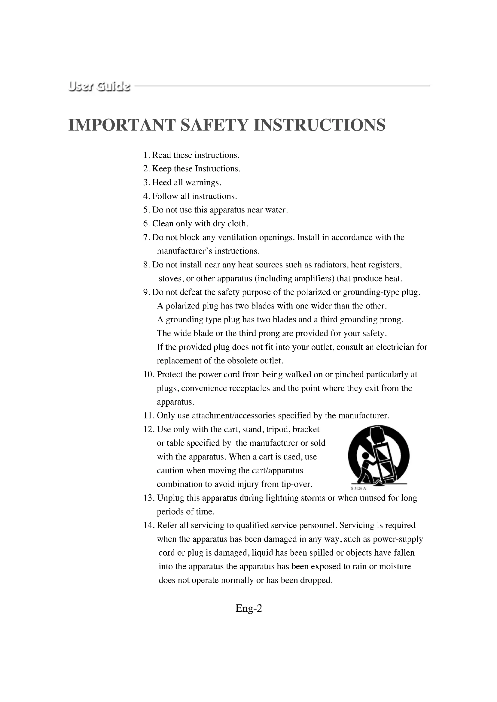
1. Read these instructions.
2. Keep these Instructions.
3. Heed all warnings.
4. Follow all instructions.
5. Do not use this apparatus near water.
6. Clean only with dry cloth.
7. Do not block any ventilation openings. Install in accordance with the
manufacturer’s instructions.
8. Do not install near any heat sources such as radiators, heat registers,
stoves, or other apparatus (including amplifiers) that produce heat.
9. Do not defeat the safety purpose of the polarized or grounding-type plug.
A polarized plug has two blades with one wider than the other. A grounding type plug has two blades and a third grounding prong. The wide blade or the third prong are provided for your safety. If the provided plug does not fit into your outlet, consult an electrician for replacement of the obsolete outlet.
10. Protect the power cord from being walked on or pinched particularly at
plugs, convenience receptacles and the point where they exit from the apparatus.
11. Only use attachment/accessories specified by the manufacturer.
12. Use only with the cart, stand, tripod, bracket
or table specified by the manufacturer or sold with the apparatus. When a cart is used, use caution when moving the cart/apparatus combination to avoid injury from tip-over.
13. Unplug this apparatus during lightning storms or when unused for long
14. Refer all servicing to qualified service personnel. Servicing is required
when the apparatus has been damaged in any way, such as power-supply cord or plug is damaged, liquid has been spilled or objects have fallen into the apparatus the apparatus has been exposed to rain or moisture does not operate normally or has been dropped. Eng-2Eng-3 Graphic Symbol Explanation The lightning flash with arrowhead symbol, within an equilateral triangle, is intended to alert the user to the presence of uninsulated ‘dangerous voltage’ within the product’s enclosure that may be of sufficient magnitude to constitute a risk of electric shock to persons. The exclamation point within an equilateral triangle is intended to alert the user to the presence of important operating and maintenance (servicing) instructions in the literature accompanying the appliance. Warning - To Prevent Fire or Shock Hazard, Do Not Expose This Monitor To Rain or Moisture. CAUTION : TO REDUCE THE RISK OF ELECTRIC SHOCK, DO NOT REMOVE COVER (OR BACK). NO USER SERVICEABLE
CAUTIONEng-4 IMPORTANT SAFEGUARDS Caution Power source is indicated on the rear of the set. It contains high-voltage parts. If you remove the cover, it may cause fire or electric shock. Do not remove the cover by yourself. (Control switches are at the front of the monitor.)
1. Read Instructions : All the safety and operating instructions should be
read before the appliance is operated.
2. Retain Instructions : The safety and operating instructions should be
retained for future reference.
3. Heed Warnings : All warnings on the monitor and in the operating
instructions should be adhered to.
4. Follow Instructions : All operating and user instructions should be
5. Cleaning : Unplug this monitor from the wall outlet before cleaning.
Do not use liquid cleaners or aerosol cleaners. Use a damp cloth for cleaning. Exception. A monitor that is meant for uninterrupted service and that for some specific reason, such as the possibility of the loss of an authorization code for a CATV converter is not intended to be unplugged by the user for cleaning or any other purpose may exclude the reference to unplugging the monitor in the cleaning description otherwise required in Item 5.
6. Attachments : Do not use attachments not recommended by Samsung
as they may cause hazards.
7. Water and Moisture : Do not use this monitor near water for example,
near a bathtub, wash bowl, kitchen sink or laundry tub in a wet basement or near a swimming pool and the like wet basement or near a swimming pool and the like.Eng-5
8. Accessories : Do not place this monitor on an unstable cart, stand,
tripod, bracket or table. The monitor may fall, causing serious injury to a child or adult and serious damage to the appliance. Use only with a cart, stand, tripod. bracket or table recommended by Samsung or sold with the monitor. Any mounting of the monitor should follow Samsung’s instructions and should use a mounting accessory recommended by Samsung.
9. Ventilation : Slots and openings in the cabinet are provided for
ventilation and to ensure reliable operation of the monitor and to protect it from overheating and these openings should never be blocked by placing the monitor on a bed, sofa, rug or other similar surface. This monitor should never be placed near or over a radiator or heat register. This monitor should not be placed in a built-in installation such as a bookcase or rack unless proper ventilation is provided or Samsung’s instructions have been adhered to.
10. Power Sources : This monitor should be operated only from the type of
power source indicated on the making label. If you are not sure of the type of power supply to your installation site, consult your Samsung dealer or local power company.
11. Grounding or Polarization : For monitors equipped with a 3-wire
grounding-type plug having a third(grounding) pin. This plug will only fit into a grounding type power outlet. This is a safety feature. If you are unable to insert the plug into the outlet, contact your electrician to replace your obsolete outlet. Do not defeat the safety purpose of the grounding-type plug.
12. Power : Cord Protection-Power supply cords should be routed so that
they are not likely to be walked on or pinched by items placed upon or against them, paying particular attention to cords at plugs, convenience receptacles and the point where they exit from the monitor.Eng-6
13. Lightning : For added protection for this monitor during a lightning
storm or when it is left unattended and unused for long periods of time, unplug it from the wall outlet and disconnect the cable system. This will prevent damage to the monitor due to lightning and power-line surges.
14. Overloading : Do not overload wall outlets and extension cords as this
can result in a risk of fire of electric shock.
15. Object and liquid Entry : Never push objects of any kind into this
monitor through openings as they may touch dangerous voltage points or short-out parts that could result in a fire or electric shock. Never spill liquid of any kind on the monitor.
16. Servicing : Do not attempt to service this monitor yourself as opening or
removing cover may expose you to dangerous voltage or other hazards. Refer all servicing to qualified service personnel.
17. Damage Requiring Service : Unplug this monitor from the wall outlet
and refer servicing to qualified service personnel under the following conditions. a. When the power-supply cord or plug is damaged. b. If liquid has been spilled or objects have fallen into the monitor. c. If the monitor has been exposed to rain or water. d. If the monitor does not operate normally by following the operating instructions. Adjust only those controls that are covered by the operating instructions as an improper adjustment of other controls may result in damage and require extensive work by a qualified technician to restore the monitor to its normal operation. e. If the monitor has been dropped or the cabinet has been damaged. f. When the monitor exhibits a distinct change in performance-this indicates a need for service.Eng-7
18. Replacement Parts : When replacement parts are required, be sure the
service technician has used replacement parts specified by Samsung or have the same characteristics as the original parts. Unauthorized substitutions may result in fire, electric shock or other hazards.
19. Safety Check : Upon completion of any service or repairs to this
monitor, ask the service technician to preform safety checks to determine that the monitor is in proper operating condition. FCC information Warning This equipment has been tested and found to comply the limits for a class A digital device, pursuant to part 15 of the FCC Rules and ICES-003 of Industry Canada. These limits are designed to provide reasonable protection against harmful interference when the equipment is operated in a commercial environment. This equipment generate, uses and can radiate radio frequency energy and, if not installed and used in accordance with the instruction manual, may cause harmful interference to radio communications. Operation of this equipment in a residential area is likely to cause harmful interference in which case the user will be required to correct the interference at his own expense. User-Installer Caution Changes or modifications not expressly approved by the party responsible for compliance could void the user's authority to operate the equipment.Eng-8 Information to user Changes or modifications not expressly approved by the party responsible for compliance could void the user's authority to operate the equipment. NOTE: This equipment has been tested and found to comply with the limits for a Class A digital device, pursuant to Part 15 of the FCC Rules. These limits are designed to provide reasonable protection against harmful interference when the equipment is operated in a commercial environment. This equipment generates, uses and can radiate radio frequency energy and, if not installed and used in accordance with the instruction manual, may cause harmful interference to radio communications. Operation of this equipment in a residential area is likely to cause harmful interference in which case the user will be required to correct the interference at his own expense. This device complies with Part 15 of the FCC Rules. Operation is subject to the following two conditions: (1) this device may not cause harmful interference and (2) this device must accept any interference received, including interference that may cause undesired operation. Changes or modifications not expressly approved by the party responsible for compliance could void the user's authority to operate the equipment. If necessary, consult your dealer or an experienced radio/television technician for additional suggestions. You may find the booklet called How to Identify and Resolve Radio/TV Interference Problems helpful. This booklet was prepared by the Federal Communications Commission. It is available from the U.S. Government Printing Office, Washington, DC 20402, Stock Number 004-000-00345-4.Eng-9 The party responsible for product compliance: SAMSUNG ELECTRONICS CO., LTD. America QA Lab of Samsung 3351 Michelson Drive, Suite #290, Irvine, CA92612 USA IC Compliance Notice This Class (A) digital apparatus meets all requirements of the Canadian Interference-Causing Equipment Regulations. Cet appareil numérique de la classe (A) respecte toutes les exigences du Règlement sur le matériel brouilleur du Canada. This Class A digital apparatus complies with Canadian ICES-003. Cet appareil numéique de la classe A est conforme à la norme NMB-003 du Canada. Warning This is a class A product. In a domestic environment this product may cause radio interference in which case the user may be required to take adequate measures.Eng-10 Contents IMPORTANT SAFETY INSTRUCTIONS .................Eng-2 IMPORTANT SAFEGUARDS................................... Eng-4 FCC information .......................................................... Eng-7 Front Panel Components and Controls ...................... Eng-11
- Data Controls : If you press CONTRAST, BRIGHT, COLOR, TINT or SHARP and then VOLUME key, you can change the value of each key. SMC-150F SMC-210F Front Panel Components and Controls
Using buttons on the front panelEng-12 CONTRAST Switch This control adjusts the contrast of the screen image. Press CONTRAST switch and then VOLUME(DATA) switch to control the contrast. BRIGHT Switch This control adjusts the bright of the screen image. Press BRIGHT switch and then VOLUME(DATA) switch to control the bright. COLOR Switch This control adjusts the color intensity of the screen image. Press COLOR switch and then VOLUME(DATA) switch to control the color intensity. TINT Switch With this switch, you can control the color to be close to natural color. For the best result, control screen image with this switch so that skin color is natural. Press TINT switch then VOLUME(DATA) switch to control the color. (Only NTSC) SHARP Switch This control adjusts the sharpness of the screen image. Press SHARP switch and then VOLUME(DATA) switch to control the sharpness.Eng-13 SMC-212F SMC-152F POWER On/Off Switch If you press this switch, the monitor is turned on and the LED of selected input signal is lit. Auto/Manual/VCR Mode Selection Button If the Auto/Manual/VCR mode selection button is pressed, a RED indicator light will be displayed for Auto mode, a GREEN indicator light for Manual mode and an ORANGE indicator light for VCR Mode.
Using buttons on the front panelEng-14 Using the Auto Mode The RED indicator light is lit when Auto Mode is selected. In the Auto mode, the camera input channels will automatically switch by following sequence: Camera 1 → Camera 2 → Camera 3 → Camera 4, where the switching interval is set in the MENU option. (In the MENU option, auto-timer, 2 to 10 seconds)
Camera 1 (After auto-timer duration) (After auto-timer duration) Camera 2 Camera 3Eng-15 Using the Auto-Skip Mode When the Auto-skip options is set in the MENU settings, and no input signals are found for the channels 2, 4 and VCR, the Monitor will operate as follows: After 1 second After 1 second After 1 second (After scanning 4 channels) Camera 2 Scanning No Input Signal Camera 3 Scanning Camera 4 Scanning No Input Signal Camera 1 Scanning After 1 second After 1 second After 1 second (After scanning 4 channels) Camera 2 Scanning No Input Signal Camera 3 Scanning Camera 4 Scanning No Input Signal Camera 1 Scanning (After auto-timer duration) (After auto-timer duration) (After auto-timer duration) Camera 1 Camera 3 Camera 1 Camera 3Eng-16 Using the Manual Mode The GREEN indicator light is lit when Manual Mode is selected. This option allows the user to manually select either Camera OR VCR input channel accordingly as follows: CAMERA 1 Button If this button is pressed, the menu setting will be set to Camera 1. CAMERA 2 Button If this button is pressed, the menu setting will be set to Camera 2. CAMERA 3 Button If this button is pressed, the menu setting will be set to Camera 3. CAMERA 4 Button If this button is pressed, the menu setting will be set to Camera 4. VCR Button If this button is pressed, the menu setting will be set to VCR.Eng-17 Using the MENU button Press the MENU button for MENU settings. MENU Button - VOLUME If the MENU Button is pressed, all user controllable menus will be displayed in the following sequence: Contrast ➔ Brightness ➔ Sharpness ➔ Color ➔ Tint(NTSC only) ➔ Auto Timer ➔ Auto Skip ➔ Camera OSD ➔ (Language) ➔ Preset To set each Menu setting
1. Press MENU button to select Menu to set
2. Use VOLUME Button to set Menu setting
3. After setting each MENU option, return to the MAIN MENU for other
menu options. (Press the MENU Button to return to the MAIN MENU)Eng-18 Settings Range of Each Button Explanation To select a specific Contrast within the setting range. To select a specific Brightness within the setting range. To select a specific Sharpness within the setting range. To select a specific Color within the setting range. To select specific Tint within the setting range. Interval of Input Channel Switching for Auto Mode Under the AUTO Mode, every channel having no input signal will be automatically skipped (ON) or will be displayed and not skipped (OFF). To display OSD menu (ON) Not to display OSD menu (OFF) English, Français, Español, Português, Italiano, Deutsch To preset all Menus to Factory Default settings. Settings Range 0~100 0~100 0~100 0~100 Red 0~100 Green 0~100 2 ~ 10 seconds ON / OFF ON / OFF
MENU Contrast Brightness Sharpness Color Tint (NTSC) Auto Timer Auto Skip Camera OSD Language (depending on the model) Preset Adjustments & Settings of the MENU options: Use VOLUME button to adjust Contrast, Brightness, Sharpness, Color, Tint and Auto Timer.
- Select each Menu and then press VOLUME button to adjust.
- Adjusted Settings of the selected Menu option is displayed.
- Press the VOLUME button to decrease setting of the menu option.
- Press the VOLUME button to increase setting of the menu option.Eng-19 Use the VOLUME Button to adjust Auto-Skip menu setting.
- Select the Auto-Skip Menu in the MENU options.
- Press the VOLUME Button to turn on and off the Auto-Skip setting. Use the VOLUME Button to adjust the preset MENU settings.
- The Menu mode will exit automatically after 20 seconds of no user input. Adjusting VOLUME
- In the MANUAL Mode, use the VOLUME button to adjust the volume of the selected channel.
- Press the VOLUME button to decrease, or press the VOLUME button to increase the volume.
- Monitor displays the volume as an adjustable signal bar.
- The volume setting will remain unchanged if no adjustment is made within 3 seconds.Eng-21 Rear Panel Components and Controls CAMERA IN (1~4), VIDEO LINE IN(A, B) Camera INPUT connector. Input connectors for up to 4(2) cameras MONITOR OUT, VIDEO LINE OUT(A,B) VIDEO OUTPUT connector. VCR IN(VIDEO) VCR INPUT connector. Connect to the VCR. AUDIO IN (1~4), AUDIO LINE IN(A, B) AUDIO INPUT connector. Select corresponding AUDIO input signals (1 – 4) AUDIO OUT, AUDIO LINE OUT(A, B) AUDIO OUTPUT connector. (Not working under AUTO Mode) AUDIO IN (VCR) VCR AUDIO INPUT connector.
SMC-210F, SMC-150FEng-23 Maintenance If the quality of the picture on the COLOR MONITOR is poor and cannot be improved, inspect all system connections and cable runs. Repairs should be performed by a qualified technician with adequate test equipment and facilities.Eng-24 Specifications SMC-152FP/SMC-150FP/SMC-152FN/SMC-150FN (NTSC/PAL) 15” diagonal, 0.6mm stripe pitch, 90° deflection SMC-152FP/152FN : 4 Channel Input/1 Channel Output. SMC-150FP/150FN : 2 Channel Input/2 Channel Output. VCR INPUT 1.0Vp-p BNC jack SMC-152FP/152FN : 4 Channel Input/1 Channel output. SMC-150FP/150FN : 2 Channel Input/2 Channel output. VCR Input RCA jack Control range of main section 100V~250V or “Indicated on the rear of the MONITOR set” 50W 365mm x 391mm x 342mm (without packing) about 16.5Kg (with packing) 360 TV lines Multiple system (NTSC/PAL) Pull in Range ± 500Hz Holding Range ± 500Hz Pull in Range ± 4Hz Holding Range ± 4Hz Pull in Range ± 400Hz Holding Range ± 400Hz 1.5Watts Less than 0.4mm Max (Center) 10% 0°C ~ +40°C 10 ~ 90% (Non-condensing) System CRT Video In/Out Audio In/Out Power Source Power Consumption Dimensions (W x D x H) Weight Resolutions Video System Horizontal Stabilization Vertical Stabilization Sub Carrier Stabilization Audio Convergence Overscan Operating Temperature Operating HumidityEng-25 Specifications SMC-212FP/SMC-210FP/SMC-212FN/SMC-210FN (NTSC/PAL) 21” diagonal, 0.75mm stripe pitch, 90° deflection SMC-212FP/212FN : 4 Channel Input/1 Channel Output. SMC-210FP/210FN : 2 Channel Input/2 Channel Output. VCR INPUT 1.0Vp-p BNC jack SMC-212FP/212FN : 4 Channel Input/1 Channel output. SMC-210FP/210FN : 2 Channel Input/2 Channel output. VCR Input RCA jack Control range of main section 100V~250V or “Indicated on the rear of the MONITOR set” 60W 490mm x 342mm x 482mm (without packing) about 31Kg (with packing) 450 TV lines Multiple system (NTSC/PAL) Pull in Range ± 500Hz Holding Range ± 500Hz Pull in Range ± 4Hz Holding Range ± 4Hz Pull in Range ± 400Hz Holding Range ± 400Hz 1.5Watts Less than 0.4mm Max (Center) 10% 0°C ~ +40°C 10 ~ 90% (Non-condensing) System CRT Video In/Out Audio In/Out Power Source Power Consumption Dimensions (W x D x H) Weight Resolutions Video System Horizontal Stabilization Vertical Stabilization Sub Carrier Stabilization Audio Convergence Overscan Operating Temperature Operating HumidityCOLOR MONITOR