KS605NXE2 - Basket SMEG - Free user manual and instructions
Find the device manual for free KS605NXE2 SMEG in PDF.

Frequently Asked Questions - KS605NXE2 SMEG
User questions about KS605NXE2 SMEG
0 question about this device. Answer the ones you know or ask your own.
Ask a new question about this device
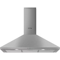
Download the instructions for your Basket in PDF format for free! Find your manual KS605NXE2 - SMEG and take your electronic device back in hand. On this page are published all the documents necessary for the use of your device. KS605NXE2 by SMEG.
USER MANUAL KS605NXE2 SMEG
Instruction booklet (EN)
كتيب التعليمات (AR)
Mode d'emploi (FR)
text_image
Min. 650mmFig. 1

natural_image
Three metallic mechanical parts: a rod, a bracket with mounting flange, and a cylindrical component (no text or symbols visible)Fig. 2
natural_image
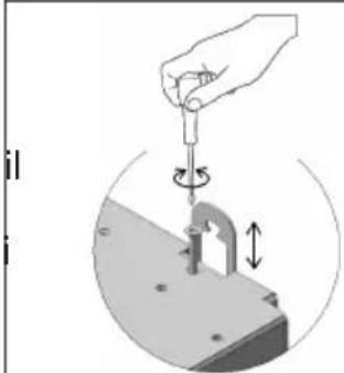
Illustration of a hand using a tool to lift a mechanical component, showing rotational motion (no text or symbols)Fig. 3

natural_image
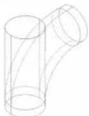
3D mechanical component diagram showing a cylindrical pipe above a base with a circular top (no text or symbols)Fig. 4

Versione FILTRANTE:
text_image
#01 #0123(A)
(B)
PULSANTIERA ELETTROMECCANICA:

Tasto ON/OFF luci
0
Tasto OFF motore
123
natural_image
Diagram showing two views of a mechanical component: (a) a circular ring with a handle, and (b) a multi-circular gear with a handle (no text or symbols)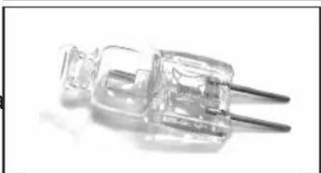
natural_image
Close-up of a transparent electrical plug with metal leads (no visible text or symbols)TRATTAMENTO DEL RAEE:
natural_image
Symbol of a trash bin crossed with diagonal lines, no text or numbers presentInstruction booklet (EN)
كتيب التعليمات (AR)
Mode d'emploi (FR)
- Read the instructions closely before installing and/or using the hood.
- The manufacturer will not be held liable for damage caused by installation that is incorrect or not up to standard.
• We recommend that all installation and adjustment procedures are carried out by trained personnel.
- When the hood is taken out of its packaging inspect it to ensure that it is intact. If the product is damaged, do not use it and contact the Smeg assistance service.
- Before making any connections, make sure that the mains voltage corresponds to the voltage shown on the label located inside the appliance.
- For Class I appliances, check that the domestic power supply guarantees adequate earthing.
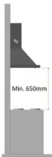
- The minimum distance between the hob and the lower part of the hood must be at least 650mm.
- The extracted air must not be conveyed in a duct used to conduct fumes from appliances powered by gas or other fuel.
- Connect the outlet for the air extracted by the hood to fumes discharge ducts with a suitable internal diameter, and no less than 120 mm.
- The room must be adequately ventilated when the hood or gas appliances are used simultaneously.
- If the power cable is damaged it must be replaced by the manufacturer or its technical assistance service, or nonetheless by an individual with a similar qualification, so as to prevent any risk.
- Comply with any legal regulations relative to the extraction of air when operating the extraction hood.
OPERATION
- Do not cook or fry in a way that creates strong flames. These could be drawn into the hood during operation and cause a fire.
- Do not flambé food under the kitchen hood; Fire hazard
- The hood can be used by individuals under the age of 8 and by individuals with physical, sensorial or mental impairments, or without experience or the required knowledge, as long as they are under supervision or have been given instructions on safe use of the appliance and are familiar with
the dangers it entails.
• Children must be supervised to ensure that they do not play with the appliance
- ATTENTION: The accessible parts can become very hot if they are used with cooking equipment.
MAINTENANCE
- Before carrying out any maintenance procedure or cleaning, disconnect the appliance from the electricity supply.
- Carry out thorough and timely maintenance of the filters in accordance with the intervals recommended by the manufacturer.
- To clean the hood surfaces, use a damp cloth and a mild liquid detergent.
- Cleaning and maintenance carried out by the user must not be performed by children without supervision:
• THE MANUFACTURER DECLINES ALL RESPONSIBILITY IF THE ABOVE INDICATIONS ARE NOT FOLLOWED
USE:
- This appliance was designed to be used as an EXTRACTION (extraction of air to the outside) or FILTER hood (recirculation of air indoors).
- EXTRACTION VERSION: To turn the hood into the extraction version connect the motor inlet, by means of a rigid or flexible pipe with a suitable internal diameter and no less than 120 ~mm , directly to the external vapour and odour extraction duct.
NB. Remove any active carbon odour-control filters.
- FILTER VERSION: If it is not possible to direct the air outdoors, the hood can be transformed into the filter version. In this version, the air and vapours are purified by active carbon filters and recirculated into the room through the lateral ventilation grilles of the flue.
Note: using the hood in filter mode can increase the level of noise perceived.
INSTALLATION INSTRUCTIONS:
The hood is supplied with all the accessories necessary for its installation. The minimum distance between the lower surface of the hood and the hob must be at least 650mm for electric hobs (Fig. 1). If the motor inlet is equipped with a non-return valve for fumes, make sure it can open and close freely.
For easy installation it is recommended to follow the procedures described below:
1) The hood must be centred with respect to the hob surface.
2) There are different installation procedures depending on the hood model. Choose one of the following fixing systems:
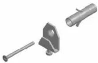
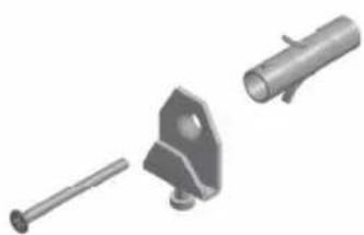
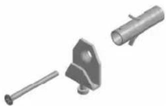
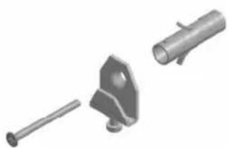
a) 2 levelling hooks that fasten on with the supplied expansion plugs (Fig. 2)
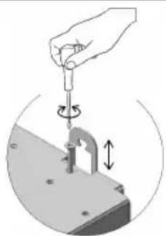
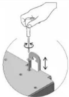
b) Rear levelling bracket that fastens on with the supplied expansion plugs (Fig. 3)
c) For island models refer to the special installation attachment.
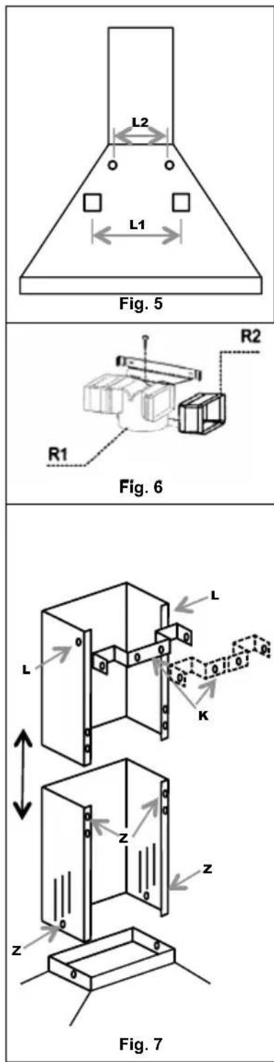
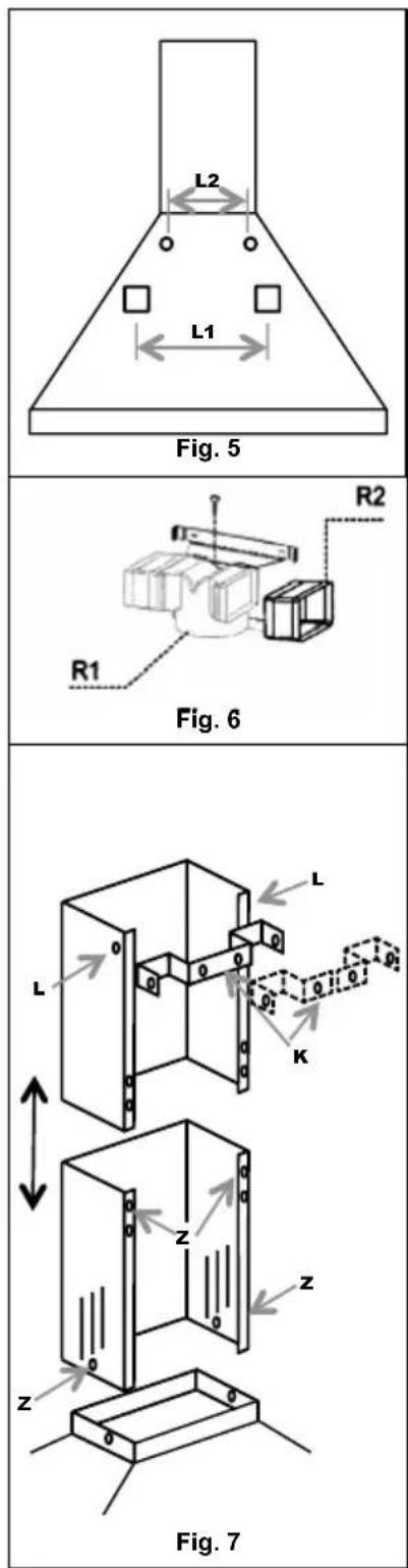
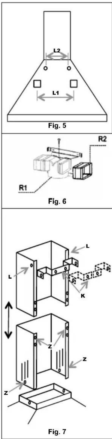
N.B.: Fixing systems a) and b) fit on to the back of the hood in the holes L1 (Fig. 5).
3) Remove the grease filters and position the hood on the wall and mark the reference position for the holes to anchor the relative fixing system.
4) Drill the 2 holes previously marked after removing the hood from the wall
5) Anchor the fixing system to the wall by tightening the expansion plug
6) Mark holes L2 on the wall to secure the plugs safely in the holes. (plugs supplied)
7) Hang the hood on the fixing system (fig. 2 and 3) and level it using the adjustment screws (fig.2).
8) Securely fix the hood by fully tightening the two expansion screws of the holes L2
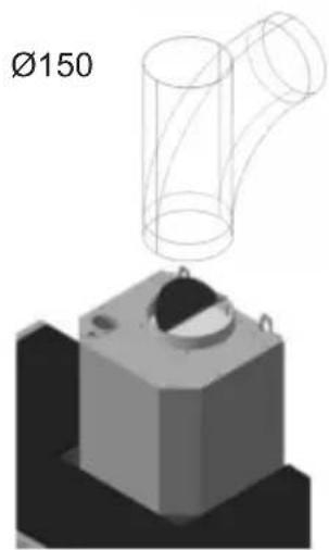
AIR CONNECTION SYSTEMS:
EXTRACTION version:
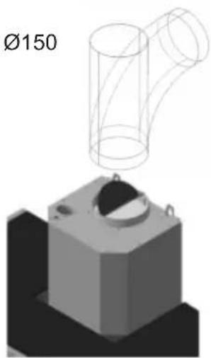
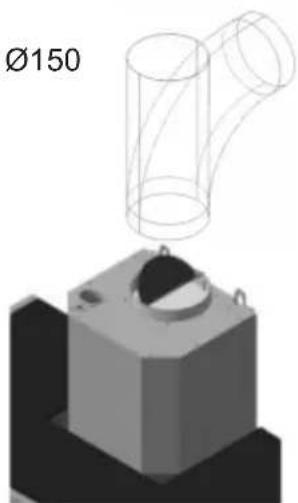
Connect the fume expulsion duct (inside diameter ∅ 150 mm) to the exhaust of the motor inlet. The expulsion duct must not have a diameter ∅ of less than 120 mm.
Note that if the hood is supplied with an active carbon filter, this must be removed (see page 8)
Deviation for Germany:
When the hood and other appliances powered by energy other than electricity are simultaneously ON, the negative pressure in the room must not exceed 4 Pa ( 4 × 10^-5 bar).
text_image
Min. 650mmFig. 1

natural_image
Three metallic mechanical parts: a rod, a bracket with mounting flange, and a cylindrical component (no text or symbols visible)Fig. 2

natural_image
Illustration of a hand using a tool to lift a small mechanical component, shown in a circular frame (no text or symbols)Fig. 3

natural_image
3D mechanical component diagram showing a cylindrical pipe above a base with a circular end cap (no text or symbols)Fig. 4

FILTER version:
Leave the motor inlet free. Install the active carbon filters as shown on page 8.
If the hood is not supplied with an active carbon filter you must buy it separately at your nearest authorised Smeg dealer.
For some models there is a standard set of fittings (fig.6) to be fixed to the wall by expansion plugs at a suitable height in order to channel the airflow in correspondence with the flue slits. Insert laterally the extensions R2 on the fitting R1. Connect the fitting R1 at the outlet of the hood body by means of a tube of diameter D.150mm.
• FLUE ASSEMBLY (fig. 7):
Position the one-piece or two-piece (K) flue bracket to the required top limit.
Mark the two holes on the wall to fix the bracket. Drill and fix the bracket with the supplied expansion plugs.
Carefully position the flue unit on the hood. Fix the lower flue to the hood by means of the screws Z. Carefully extend the top flue to the upper limit.
Secure the top flue to the flue bracket K using the screws L.
• ELECTRIC CONNECTION
• We recommend that electric connections are carried out by a professional installer.
In the case of a direct electric connection to the mains, between the appliance and the mains, place a bipolar switch with a minimum opening of 3mm between contacts, sized to the load and compliant with the current regulations.
USER INSTRUCTIONS
• CONTROLS UNIT
For an optimal and efficient use of the product it is advisable to start the hood a few minutes before you start cooking and to keep it on for at least 15min after you have finished cooking or until steam and odours have completely disappeared.
To start the hood, identify the command type of the hood and then follow the relative indications:
SLIDER:
- Slider (A) lighting ON/OFF
- Slider (B) with four positions:
①
Motor OFF
123
ON/Speed selection
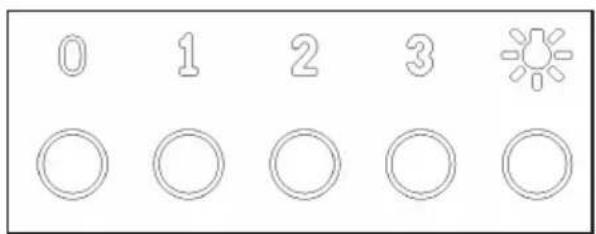
ELECTRO-MECHANICAL PUSHBUTTON PANEL:

Lights ON/OFF key
0
Motor OFF key
123
Power key/hood speed selection
KNOBS:
Hood speed selection

Start timed intensive speed

Timed intensive speed:
The timed intensive function is that mode of service for which the hood, for a limited time, works at its maximum capacity. The timed intensive speed of the hood is activated by turning the knob (B) clockwise from position 3. Once the timed intensive speed is activated, the knob automatically turns to position 3. The intensive speed can be switched off by turning the control (B) counter-clockwise again. When the intensive speed timer has expired it returns to the third speed by default.
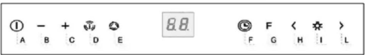
2-DIGIT 10-KEY CAPACITIVE PUSHBUTTON BOARD:
text_image
① - + 📋 8.8 A B C D E F G H I L| Key Function Display | ||
| A Turns the suction motor on / off. Displays the set speed | ||
| B Decreases the operation speed. Displays the set speed | ||
| C Increases the operation speed. Displays the set speed | ||
| D | Activates the Intensive speed from any speed even with the motor off, this speed is timed. At the end, the system returns to the speed previously set. Suitable for dealing with the maximum emissions of cooking fumes. | Displays alternatively HI |
| Hold the button down for about 5 seconds, when all loads are off (Motor + Light), to switch the keyboard lock On / Off. | "--" Keyboard lock On. | |
| E | 24 H functionActivates the motor at the first speed and allows extraction for 10 minutes every hour. | It displays 24 and the point at the bottom right flashes once a second, while the motor is in operation. Press the key to disable it. |
| Holding the button down for about 5 seconds when all loads are off (Motor + Light), holding key "B" down during the animation, the Active Carbon Filters Alarm switches On / Off. | Displays a rotary animation for 5 seconds. "EF" flashes twice in activation. "EF" flashes once in deactivation. | |
| F | Delay functionEnables the automatic shutdown delay of 30'. Suitable for removing residual odours. Can be activated from any position. You disable it by pressing the key or turning the motor off. | Displays the operating speed and the point on the lower right flashes. |
| G | With the filter alarm in progress, pressing the key for about 3 seconds resets the alarm. | After the procedure, the signal previously displayed turns off:FF signals the need to wash the metallic grease filters. The alarm comes on after 100 hours of actual operation of the Hood.EF signals the need to replace the active carbon filters and the metallic grease filters must also be washed.The alarm comes on after 200 hours of actual operation of the Hood. |
| H | Decreases the light intensity at each press of the Key in a cyclic manner. | |
| 1 Turns the lighting system on and off at maximum intensity. | ||
| L | Increases the light intensity at each press of the Key in a cyclic manner. | |
Keyboard lock command: you can lock the keyboard, for example, to clean the glass surface, when the Hood has the motor and lights switched off. By pressing key D for about 5 seconds, you can enable or disable the keyboard lock which is always confirmed with:
“- -” Keyboard lock On.
1-DIGIT CAPACITIVE PUSHBUTTON BOARD:

A

B

C


D

F
| KEY FUNCTION DISPLAY | ||
| A SWITCH THE SUCTION MOTOR ON / OFF. DISPLAYS THE SET SPEED | EED | |
| B DECREASE THE OPERATING SPEED DISPLAYS THE SET SPEED | ||
| C | INCREASE THE OPERATING SPEEDSTART TIMED INTENSIVE SPEED | DISPLAYS THE SET SPEEDFLASHING TIMED INTENSIVESPEED |
| D TURN THE LIGHTING SYSTEM ON AND OFF | ||
| F ENABLES THE AUTOMATIC SHUTDOWN DELAY OF 15' FLASHES | ||
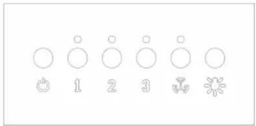
SOFT TOUCH ELECTRONIC PUSHBUTTON BOARD:
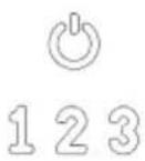


Motor OFF key/ Filters reset key
Power key/hood speed selection
Start timed intensive speed
Lights ON/OFF key
text_image
Diagram showing seven circular symbols with corresponding icons and numbers, possibly representing a basic pattern or selection system.The timed intensive function is that mode of service for which the hood, for a limited time, works at its maximum capacity.
Activating the function is displayed by the LED located under the key flashing. When the intensive speed timer has expired it returns to the third speed by default.
OPTIONAL FUNCTIONS:
- TIMED AUTO POWER OFF: By pressing one of the motor speed keys (2-3), twice, you will activate the function "Timed Auto Power Off" which turns off both lights and hood motor after 10 mins. Activating this function is demonstrated by the LED immediately above the pressed button flashing.
- FILTER CLEANING SIGNAL: the simultaneous flashing of the 4 LEDs, (programmed to run every 200h of operation), is to indicate the need to clean /replace the filters.
By pressing the OFF button , the 200h time can be reset. N.B. Accidentally pressing the OFF button before the 200h does not result in the filter being reset in the filter cleaning memory. It is good practice to clean the grease filters and replace the active carbon filters every 200h of operation.
N.B. In some countries, the 4-speed version is also available, with the layout shown on the right, where:

Filters Reset Key

FUNCTIONS AND MAINTENANCE:
Before performing any maintenance and/or cleaning always disconnect the hood from the power supply
Regular cleaning guarantees good operation and a long appliance service life. The grease filters and filter hoods with carbon filters require special care.
N.B. The accumulation of grease inside the filter panels as well as affecting the performance of the extractor, can also create a fire hazard.
EXTERNAL CLEANING: The external and internal cleaning of the hood must be carried out using a damp cloth and mild liquid detergent. Completely avoid the use of solvents or abrasives. It is recommended to use specific products, following the instructions on the product. It is advisable to clean the hood by always rubbing the steel in the direction of the surface finish.
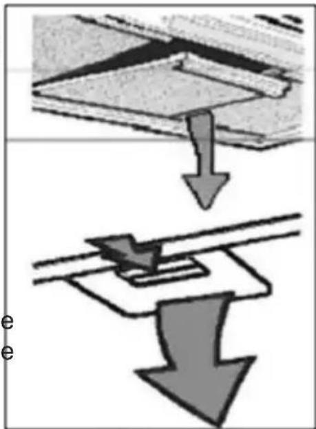
METAL FILTER CLEANING:
Particular attention should be paid to the metal grease filter panels. The accumulation of grease inside the filter panels as well as affecting the performance of the extractor, can also create a fire hazard.
In order to minimise the risk of fire, the filters must be cleaned regularly, at least once a month or with greater frequency in the case of a particularly intensive use of the appliance.
After identifying your hood model, remove one filter at a time as shown in the next figure. Thoroughly wash filters with a mild detergent either by hand or in the dishwasher. Replace the filters, making sure that the handle is on the outside of the hood
text_image
Diagram illustrating a mechanical or structural process with downward arrows indicating direction of movement or force.REPLACING CARBON FILTERS: (Only for the filter version)
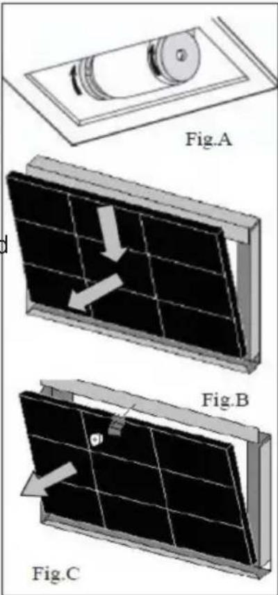
The carbon filters are capable of retaining odours until the carbon reaches saturation level. They cannot be washed and they are not renewable, therefore, it is recommended to replace them at least every six months or more often if the hood is used often.
Before starting operations make sure the electrical power supply to the hood is disconnected.
Access the active carbon filters by removing the metal filters as described above. With the help of the figures, identify the carbon filters kit supplied with the hood.
In the case of the disc filter, simply tilt the two filters by 90^ as shown in (fig.A) and then extract them from their housing.
In the case of a cartridge filter attached with springs, (fig.B) exert the pressure required to counteract the resistance of the spring and then remove the filter
In the case of a cartridge filter blocked with a bracket and threaded knob, (fig. C), unscrew the knob, remove the locking bracket and then remove the active carbon filter. Replace the carbon filters and the metal non-grease filters by performing the operations in inverse order
text_image
Fig.A d Fig.B Fig.CREPLACEMENT LAMPS:
Before performing any maintenance and/or cleaning always disconnect the hood from the power supply
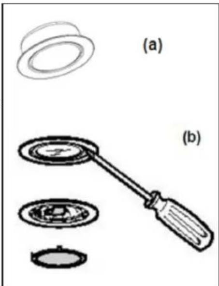
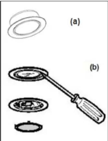
Depending on the model, the hood can be equipped with different types of lighting, with LED or halogen lamps:
a) WITH LED LIGHTS: The LED lights guarantee a significant number of hours of operation. Should it be replace due to being worn or faulty, the entire spotlight must be replaced. In this case, contact qualified Technical Support. This appliance is equipped with Class 1M white LED light, in accordance with EN standard 60825-1: 1994 + A1:2002 + A2:2001; maximum emitted optical power@439nm: 7μW. Do not look directly at the light with optical instruments (binoculars, magnifying glass...).
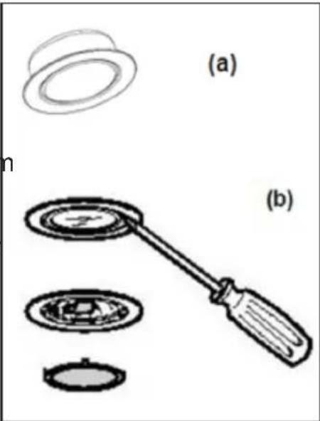
b) Halogen: lamp with G4 fitting, 20W power and 12V voltage. Replace the lamp by removing the glass support ring of the spotlight with a screwdriver. Once the glass is removed, remove the faulty lamp from its housing and fit the new lamp. Replace the glass of the spotlight by blocking it with the ring.
Code ILCOS: HSG/C/UB-20-12-G4
natural_image
Diagram showing two views of a mechanical component: (a) a circular ring with a handle, and (b) a multi-circular gear with a handle (no text or symbols)
natural_image
Close-up of a transparent electrical plug with two leads (no visible text or symbols)WEEE DISPOSAL:

natural_image
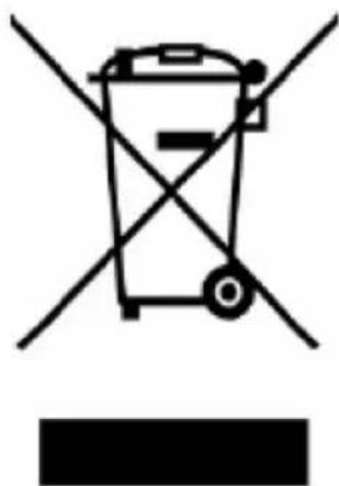
Symbol of a trash bin crossed with no text or numbers, representing waste sorting or disposal (no text present)Pursuant to art. 26 of the Italian Legislative Decree dated 14 March 2014, no. 49 "Implementation of directive 2012/19/EU on Waste Electrical and Electronic Equipment (WEEE)"
The crossed out wheeled bin symbol on the equipment or its packaging indicates that the product at the end of its useful life must be collected separately from other waste.
Therefore, any products that have reached the end of their useful life must be given to waste disposal centres specializing in separate collection of waste electrical and electronic equipment.
As an alternative to autonomous disposal, the device you want to dispose of can be given back to the retailer at the time of purchasing new similar equipment.
At electronic product retailers with a sales area of at least 400 m^2 , it is possible to return, without any obligation to buy, electronic products to dispose of with dimensions below 25 cm free of charge.
The separate collection for the delivery of the equipment to recycling, to treatment and environmentally compatible disposal helps avoid possible negative effects on the environment and health and promotes the reuse and/or recycling of materials that make up the equipment.
natural_image
Symbol of a trash bin crossed with no text or numbers, representing waste sorting or disposal (no text present)natural_image
Diagram showing two labeled parts (a) and (b) with circular components and a tool, no text or symbols present.(b

natural_image
Close-up of a transparent plastic electrical plug with two leads (no text or symbols visible)natural_image
Diagram showing a mechanical assembly with downward force arrows, no text or symbols presenttext_image
Sequence of circular icons with numbers 1, 2, 3, and a flower-like symbol, likely representing a sequence or pattern.text_image
① - + A B C D E 8.8 F G H I Lلوحة التحكم
natural_image
Simple line drawing of a 3D pipe fitting with no text or symbols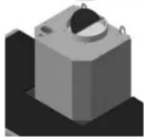
natural_image
3D rendered mechanical component with a cylindrical top and mounting base (no text or symbols)4 alشكل
• الكهربائية
ة المصنعة. • أجر
سائل محابد.
• إشراف
عليهم.
إردة أعلاه.
الاستخدام:
• عادة تدوير
الهواء في الداخل.
• مرن بقطر
Instruction booklet (EN)
كتيب التعليمات (AR)
Mode d'emploi (FR)
text_image
Min. 650mmFig. 1
à
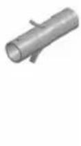
Fig. 2

natural_image
Illustration of a hand using a tool to lift a small mechanical component, shown in a circular frame (no text or symbols)Fig. 3
∅150
natural_image
Simple line drawing of a cylindrical pipe fitting (no text or symbols)
natural_image
3D rendered mechanical component with a circular top and mounting base (no text or symbols)Fig. 4
Version FILTRANTE :
natural_image
Simple diagram of two switches with icons and numbers, no readable text or symbols(A)
(B)
text_image
0 1 2 3 ◯◯◯◯◯◯
text_image
0 1 2 3 4 5 6 7 8 9 10 11 12 13 14 15 16 17 18 19 20 21 22 23 24 25 26 27 28 29 30 31 32 33 34 35 36 37 38 39 40 41 42 43 44 45 46 47 48 49 50 51 52 53 54 55 56 57 58 59 60 61 62 63 64 65 66 67 68 69 70 71 72 73 74 75 76 77 78 79 80(A)
(B)

text_image
Sequence of circular icons with numbers 1, 2, 3, and star symbols below, likely representing a sequence or pattern.natural_image
Diagram showing a mechanical assembly with downward force arrows, no text or symbols presentREEMPLACEMENT DES LAMPES:
natural_image
Close-up of a transparent plastic electrical plug with metal leads (no text or symbols visible)TRAITEMENT DU DEEE :

natural_image
Symbol of a trash bin crossed with no text or numbers, representing waste sorting or disposal (no text present)Instruction booklet (EN)
كتيب التعليمات (AR)
Mode d'emploi (FR)
text_image
Min. 650mmFig. 1

natural_image
Three metallic mechanical parts: a rod, a bracket with mounting flange, and a cylindrical component (no text or symbols visible)Fig. 2

natural_image
Illustration of a hand using a tool to lift a small mechanical component (no text or symbols visible)Fig. 3

natural_image
3D mechanical component diagram showing a cylindrical pipe above a base with a circular end cap (no text or symbols)Fig. 4

UMLUFTVERSION:
text_image
Diagram showing seven circular symbols with corresponding icons: power, 1, 2, 3, a leaf, and a flower.text_image
Diagram illustrating a mechanical or structural process with downward arrows indicating direction, accompanied by partial text labels.ILCOS-Code: HSG/C/UB-20-12-G4
natural_image
Technical illustration showing a circular component and a tool with three circular components, labeled (a) and (b), with no visible text or symbols.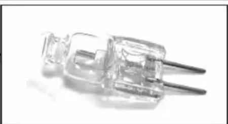
natural_image
Close-up of a transparent plastic electrical plug with two leads (no text or symbols visible)natural_image
Symbol of a trash bin crossed with no text or numbers, representing environmental restriction (no text present)Instruction booklet (EN)
كتيب التعليمات (AR)
Mode d'emploi (FR)
text_image
Min. 650mmFig. 1

natural_image
3D rendered mechanical parts including a rod, bracket, and cylindrical shaft (no text or symbols)Fig. 2

natural_image
Illustration of a hand using a tool to lift a U-shaped clamp or bracket (no text or symbols present)Fig. 3
natural_image
3D mechanical component diagram showing a cylindrical pipe above a base with a circular knob (no text or symbols)Fig. 4

Version FILTRERING:
Åbningen til motoren skal holdes fri. De aktive kulfiltre installeres som vist på side 8.
text_image
① - + 📋 8.8 A B C D E F G H I Ltext_image
Image showing seven circular icons with corresponding numerical labels below each, likely representing a rating or selection system.natural_image
Diagram showing a mechanical assembly with downward force arrows, no text or symbols presentnatural_image
Diagram showing two views (a) and (b) of a mechanical component with circular parts and a tool, no text or symbols present.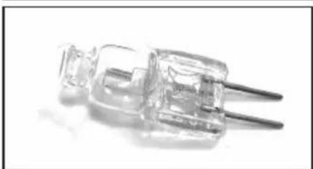
natural_image
Close-up of a transparent plastic electrical plug with wires, no visible text or symbolsBEHANDLING AF WEEE

natural_image
Symbol of a trash bin crossed with no text or numbers, representing environmental restriction (no text present)Instruction booklet (EN)
كتيب التعليمات (AR)
Mode d'emploi (FR)
text_image
Min. 650mmFig. 1
natural_image
3D rendered mechanical parts including a rod, bracket, and cylindrical shaft (no text or symbols)Fig. 2

natural_image
Illustration of a hand using a tool to lift a small mechanical component, shown in a circular frame (no text or symbols)Fig. 3
natural_image
3D mechanical component diagram showing a cylindrical pipe above a base with a circular top (no text or symbols)Fig. 4

Versión FILTRANTE:
text_image
① - + 📋 8.8 A B C D E F G H I Ltext_image
Diagram showing eight circular symbols with corresponding icons: power, 1, 2, 3, a butterfly, and a flower.natural_image
Diagram showing a mechanical assembly with downward force arrows, no text or symbols presentnatural_image
Diagram showing two labeled parts (a) and (b) with circular components, no text or symbols present.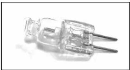
natural_image
Close-up of a transparent plastic electrical plug with wires, no visible text or symbolsTRATAMIENTO DEL RAEE:

natural_image
Symbol of a trash bin crossed with no text or numbers, representing environmental restriction (no text present)Instruction booklet (EN)
كتيب التعليمات (AR)
Mode d'emploi (FR)
text_image
Min. 650mmFig. 1

natural_image
Three metallic mechanical components with different mounting holes and shafts (no text or symbols visible)Fig. 2
natural_image
Illustration of a hand using a tool to lift a small mechanical component (no text or symbols visible)Fig. 3

natural_image
3D mechanical component diagram showing a cylindrical pipe above a base with a circular end cap (no text or symbols)Fig. 4

Wersja FILTRUJĄCA:
text_image
① - + 📋 8.8 A B C D E F G H I Ltext_image
Diagram showing seven circular symbols with corresponding icons: a lightning bolt, a circle labeled 1, a circle labeled 2, a circle labeled 3, a circle labeled 4, and a flower-like symbol.natural_image
Diagram showing a mechanical assembly with downward arrows indicating force or motion (no text or symbols present)Kod ILCOS: HSG/C/UB-20-12-G4
natural_image
Technical illustration showing a circular component and a tool with three circular parts, labeled (a) and (b), without any text or symbols.
natural_image
Close-up of a transparent electrical plug with two leads (no visible text or symbols)LIKWIDACJA ZSEE:

natural_image
Symbol of a trash bin crossed with a diagonal line, no text or numbers presentInstruction booklet (EN)
كتيب التعليمات (AR)
Mode d'emploi (FR)
text_image
Min. 650mmFig. 1

natural_image
Three metallic mechanical components with different end caps and shafts, shown from different angles (no text or symbols visible)Fig. 2

natural_image
Illustration of a hand using a tool to lift a small mechanical component, shown in a circular frame (no text or symbols)Fig. 3

natural_image
3D mechanical component diagram showing a cylindrical pipe above a base with a circular base and mounting holes (no text or symbols)Fig. 4

VERSÃO FILTRANTE:
text_image
① - + 📋 8.8 A B C D E F G H I Ltext_image
Diagram showing eight circular symbols with corresponding icons: power, 1, 2, 3, flowers, and a flower-like symbol.text_image
Diagram illustrating a mechanical or structural process with downward arrows indicating direction of movement or force.natural_image
Technical illustration showing a circular component and a tool with three circular components, labeled (a) and (b), with no visible text or symbols.
natural_image
Close-up of a transparent electrical plug with two leads (no visible text or symbols)TRATAMENTO DO RAEE:
natural_image
Symbol of a trash bin crossed with no text or numbers, representing waste sorting or disposal (no text present)Instruction booklet (EN)
كتيب التعليمات (AR)
Mode d'emploi (FR)
text_image
Min. 650mmFig. 1

natural_image
Three metallic mechanical components: a rod, a bracket with mounting hole, and a cylindrical part (no text or symbols visible)Fig. 2

natural_image
Illustration of a hand using a tool to lift a small mechanical component, shown in a circular frame (no text or symbols)Fig. 3

natural_image
3D mechanical component diagram showing a cylindrical pipe above a base with a circular housing (no text or symbols)Fig. 4

FILTERVERSIE:
text_image
Diagram showing seven circular symbols with corresponding icons: power, 1, 2, 3, flower, and flower-like symbol.AAN/UIT-toets lampen
natural_image
Diagram showing a mechanical assembly with downward arrows indicating force or motion (no text or symbols)natural_image
Diagram showing two labeled parts (a) and (b) with circular components and a tool, no text or symbols present.
natural_image
Close-up of a transparent electrical plug with two leads (no visible text or symbols)VERWERKING VAN AEEA:

natural_image
Symbol of a trash bin crossed with no text or numbers, representing waste sorting or disposal (no text present)Instruction booklet (EN)
كتيب التعليمات (AR)
Mode d'emploi (FR)
text_image
Min. 650mmFig. 1

natural_image
Three metallic mechanical components with different mounting holes and shafts (no text or symbols visible)Fig. 2

natural_image
Illustration of a hand using a tool to lift a small mechanical component, shown in a circular frame (no text or symbols)Fig. 3

natural_image
3D mechanical component diagram showing a cylindrical pipe above a base with a circular knob (no text or symbols)Fig. 4

FILTERVERSJON:
text_image
① - + 📋 8.8 A B C D E F < ★ > F G H I Ltext_image
Sequence of circular icons with numbers 1, 2, 3 and corresponding symbols including a leaf and flowernatural_image
Diagram showing a mechanical assembly with downward force arrows, no text or symbols presentnatural_image
Close-up of a transparent plastic electrical plug with metal leads (no text or symbols visible)BEHANDLING AV EE-AVFALL:
natural_image
Symbol of a trash bin crossed with no text or numbers, representing environmental restriction (no text present)Instruction booklet (EN)
كتيب التعليمات (AR)
Mode d'emploi (FR)
text_image
Min. 650mmFig. 1
natural_image
3D rendered mechanical parts including a rod, flange, and cylindrical shaft (no text or symbols)Fig. 2

natural_image
Illustration of a hand using a tool to lift a small mechanical component (no text or symbols visible)Fig. 3

natural_image
3D mechanical component diagram showing a cylindrical pipe above a base with a circular dial (no text or symbols)Fig. 4
text_image
① - + 📋 ⓣ 8.8 A B C D E F < ★ > F G H I Ltext_image
Diagram showing seven circular symbols with corresponding numbers below each, likely representing a sequence or pattern.natural_image
Diagram showing a mechanical assembly with downward force arrows, no text or symbols presentnatural_image
Diagram showing two labeled parts (a) and (b) with circular components, one being cut by a tool, no text or symbols present.
natural_image
Close-up of a transparent plastic electrical plug with wires, no visible text or symbolsnatural_image
Symbol of a trash bin crossed with no text or numbers, representing environmental restriction (no text present)Instruction booklet (EN)
كتيب التعليمات (AR)
Mode d'emploi (FR)
text_image
Min. 650mmFig. 1
natural_image
Three metallic mechanical parts: a rod, a bracket with mounting flange, and a cylindrical component (no text or symbols visible)Fig. 2
natural_image
Illustration of a hand using a tool to lift a small mechanical component, shown in a circular frame (no text or symbols)Fig. 3
natural_image
3D mechanical component diagram showing a cylindrical pipe above a base with a circular base and mounting holes (no text or symbols)Fig. 4

VERSION MED ÅTERCIRKULERING:
text_image
Diagram illustrating a mechanical or structural process with downward arrows indicating direction of movement or force.BYTE AV KOLFILTER: (Endast för den filtrerande versionen)
natural_image
Diagram showing two labeled parts (a) and (b) with circular components, no text or symbols present.
natural_image
Close-up of a transparent electrical plug with two leads (no visible text or symbols)Behandling av WEEE:
natural_image
Symbol of a trash bin crossed with a diagonal line, no text or numbers presentInstruction booklet (EN)
كتيب التعليمات (AR)
Mode d'emploi (FR)
text_image
Min. 650mmFig. 1
natural_image
Three metallic mechanical parts: a rod, a bracket with mounting flange, and a cylindrical component (no text or symbols visible)Fig. 2

natural_image
Illustration of a hand using a tool to lift a small mechanical component, shown in a circular frame (no text or symbols)Fig. 3

natural_image
3D mechanical component diagram showing a cylindrical pipe above a base with a circular end cap (no text or symbols)Fig. 4
SUODATTAVA malli:
text_image
① - + 📋 8.8 A B C D E F G H I Ltext_image
Diagram showing seven circular symbols with corresponding icons: power, 1, 2, 3, a leaf, and a flower-like symbol.natural_image
Diagram showing a mechanical assembly with downward force arrows, no text or symbols presentnatural_image
Diagram showing two labeled parts (a) and (b) with circular components, no text or symbols present.
natural_image
Close-up of a transparent electrical plug with two leads (no visible text or symbols)SÄHKÖ- JA ELEKTRONIIKKALAITEROMUN KÄSITTELY:
natural_image
Simple line drawing of a trash bin with crossed lines indicating no waste or discharge (no text or symbols)