
PW45 - Electric bike YAMAHA - Free user manual and instructions
Find the device manual for free PW45 YAMAHA in PDF.

| Product type | Electric Assisted Bicycle (fast EAB / Speed Pedelec) |
| Motor | Brushless DC motor, 500 W |
| Assistance speed range | 0 to less than 45 km/h |
| Battery | Lithium-ion (type PASB2), 36 V nominal, 11 Ah, 40 cells |
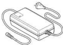
| Charger | Type PASC3, input AC 220-240 V / 50-60 Hz, output DC 42 V / 4.0 A, max power 310 VA / 180 W |
| Display unit | Removable LCD screen, USB 2.0 Micro-B port, max output 500 mA / 5 V |
| Assistance modes | High performance, Standard, Eco, Eco+, Off |
| Walk assistance function | Assistance without pedaling for up to 5 seconds (max speed depending on gear ratio) |
| Battery indicator | 11-segment scale on screen, 4 LEDs on battery |
| Auto power off | After 5 minutes of inactivity |
| Lighting | Brake light and license plate light mandatory since 2016 (depending on model) |
| Battery maintenance | Clean with a damp cloth, store at 10-20 °C with partial charge (1-2 LEDs) |
| General maintenance | Do not use a pressure washer; have it checked by an authorized dealer if problems occur |
| Safety | Do not disassemble, do not short-circuit, do not expose to fire, use only the supplied charger |
| Frame warranty | 5 years |
| Component warranty | 2 years (battery: 700 cycles at 50% capacity) |
| Spare parts / repairability | Original parts recommended; some components (motor, battery, brakes) require Winora-Staiger GmbH validation |
| Approval and legal use | Classified as moped (L1e), compulsory insurance, helmet required depending on country, bike lane prohibition in some cases |
| Total permissible weight | Up to 130 kg (depending on bike model) |
| Country of manufacture | China (charger), Japan (design) |
Frequently Asked Questions - PW45 YAMAHA
User questions about PW45 YAMAHA
0 question about this device. Answer the ones you know or ask your own.
Ask a new question about this device
Download the instructions for your Electric bike in PDF format for free! Find your manual PW45 - YAMAHA and take your electronic device back in hand. On this page are published all the documents necessary for the use of your device. PW45 by YAMAHA.
USER MANUAL PW45 YAMAHA
Model overview and max. permissible total weight for model year 2016
Definition
The max. permissible total weight consists of the maximum weight of the vehicle, rider and load.
Pedelec: Pedal electric cycle
EPAC: Electrically power assisted cycles
XII - English English - XIII
S-Pedelec: Legal and technical information
Speed Pedelec (short S-Pedelec) or Speed EPAC:
Pedelec: Pedal electric cycle
EPAC: Electrically power assisted cycles
Both terms mean a bicycle with electrical power assist, which only supports the rider when pedalling. The assistance stops at 25 km/h. A EPAC resp. pedelec is classified as bicycle according to traffic law.
Speed: The prefix, Speed* signalizes that the EPAC / Pedelec assists up to a speed of 45 km/h. Also an only electric use up to 20 km/h is possible. Please see below for traffic law information for Speed EPAC.
Legal information
You can find an overview of the specific regulations in the respective countries in chapter „Country specific rules“.
Present situation: March 2016
Please note that the legal information in this overview may lose its topicality.
Please further note that different regulations may partly apply in different countries. Please read chapter for „country specific rules“.
The following instructions do not claim to legal correctness, errors excepted.
Difference between a „normal“ Pedelec / Bicycle and a S-Pedelec
Please note that your S-Pedelec is a motor vehicle class L1e and not a pedelec / bicycle, with all resulting consequences regarding traffic law, insurance law, authorisation requirement if necessary, criminal law.
Liability insurance
It is mandatory to be in possession of a moped liability insurance in order to drive a S-Pedelec on public means. Applicable insurances you can receive from insurances or also banks.
Insurance tag
You will receive an insurance tag from your insurer. It has to be mounted on the license plate holder of the S-Pedelec. If there is an obligation to authorize the S-Pedelec in a country, you have to mount a license plate instead of the insurance tag.
Authorisation requirement & license plate
Some countries might have an authorisation requirement and thus requires a license plate (comparable with a motorcycle). Please read the chapler „country specific rules“
CoC document / EG declaration of compliance
CoC = Certificale of Conformity
This document is enclosed to your S-Pedelec and clearly assigned to this vehicle. The CoC confirms that the vehicle corresponds to the authorised type. You need the CoC documents to insure your vehicle. Furthermore you have to carry the CoC documents with you while using the S-Pedelec.
Please note:
Keep the CoC stored securely. You need this to insure the vehicle. In case of a re-sale of the vehicle the buyer will ask for the CoC. A subsequent drafting of a CoC duplicate is associated with high effort and costs.
Non EU countries
In Non-EU countries it is not ensured that the provided EG declaration of compliance suffices. E.g. for Switzerland an own type authorisation and vehicle ID is required.
Classification of the S-Pedelec as motor assisted bicycle (moped)
According to the current, however, not undisputed legal opinion the S-Pedelecs are considered as motor assisted bicycle (moped). This classification is based on the view that the maximum design speed, which is a b.0. significant for the classification, is the speed you can reach only with the motor drive. This is for S-Pedelecs <20 km/h, nevertheless you can reach a speed of up to 45 km/h with pedaling assistance. Up until now the German Department of Motor Vehicles has this opinion and approves vehicles of this type with a maximum design speed of <20 km/h.
The S-Pedelecs of Winora-Staiger GmbH are all approved with a maximum design speed of <20 km/h. This is described in the certificale of conformity. (CoC)
Driver's license, cycle tracks, helmet compulsory
Information on this topic in chapter "country specific rules".
XIV - English English - XV
Roads closed for motor vehicles
You are not allowed to use such roads, e.g. in the depiction on the right designated forest roads. More information in the chapter „country specific rules“.

Transport of children / goods with a S-Pedelc of Winora Staiger GmbH
The transport of children or other goods in a trailer with a S-Pedeloc of Winora-Staiger GmbH is not allowed. Furthermore the transportation of children in a trailer in legally forbidden in Germany.
There is a possibility of transporting a child in a child seat, however, this is not allowed by Winora-Slaiger GmbH.
Winora-Staiger GmbH does not assume any liability for damages, resulting from the use of a trailer and/or child seat in combination with the S-Pedelec.
Minimum tread depth
Please note that for motor vehicles like the S-Pedelec a minimum tread depth of 1 mm is required.
Technical information
Type approval and jurdistiction
Our S-Podelocs underwent a type approval at the German Department of Motor vehicles and are approved as motor vehicle. During this process certain components were specified, which can be used with this vehicle. If this vehicle is not specified with these components or - as described in the following - with a alternatively authorized components, the type approval loses its validity.
Specialities of certain components of the motor vehicle S-Pedelec in comparison to conventional pedelec / bicycle components
Several components of the S-Pedeloc most certain requirements of a motor vehicle of class L1c. They differ from conventional components of pedelocs / bicycles. This results from the requirements of the respective EU regulation. In non-EU countries, like e.g. Switzerland, several of these requirements might not be valid or other requirements might apply.
frame / fork
These load-carrying components of the S-Pedelec were constructed to bear the higher loads due to the higher speed in comparison to a pedelec / bicycle.
licence plate holder
This part is constructed in a way so it can hold the plate according to the regulations (visibility, angle)
rear view mirror
This part is mandatory for motor vehicles. It is ECE-tested. You recognize an approved mirror by the E-marking.
brake lever
The brake levers for two-wheeled motor vehicles have a spherical balls at the ends. Conventional pedelec / bicycle brake levers don't have these.
stand
The stand must pass several stability tests and furthermore must hold in automatically, as soon a it is completely weight relieved.
lateral reflectors
They have to be orange and non-triangle and have to have a ECE type approval. Their placing spot has to meet certain visibility requirements and must not be changed. You recognize an approved reflector by the E-marking
brake light
Since 2016 the brake light is mandatory for new type approvals.
licence plate lighting
The licence plate lighting is mandatory for all S-Pedelecs produced from 2016.
daytime running light / continuous lighting
A continuously activated daytime running light / continuous lighting is mandatory for all S-Pedeless produced from 2016.
tyres
The tyres need an approval according to ECE R75. You recognize an approved tyre by the E-marking. For the possible tyre sizes please see certificate of conformity.
XVI - English English - XVII
Structural changes on your S-Pedelec
Since the S-Pedelec is a motor vehicle there are several restrictions concerning structural changes. Table 1 indicates which components can be replaced under which conditions.
Table 1: S-Padelac components and conditions for replacement
| Following components on our S-Pedelec can be replaced ... | ||
| a) only by original components | b) without approval1 | c) only with official approval of Winora-Staiger GmbH |
| frame grips fork | ||
| drive unit shift lever handlebar | brakes | |
| battery | saddle stem | |
| seat post clamping ring gear shift | ||
| chain chainwheel | ||
| headset cranks | ||
| tube reflectors | ||
| lyres (size as in CoC document and others approved by Winora; have to be type approved) | front / rear light (must have same illuminance and must be mounted on the same position) | |
| bell mirror | ||
| carrier (max. +15% of original dimensions, position of licence plate holder must remain the same)Note: max. carrier load is 15kg | seat post | |
| sland | ||
| mud guard (must correspond with the original dimensions +/- 15%) | rims/hubs/wheels | |
| licence plaler holder | ||
Approval of alternative components by Winora-Staiger GmbH
If it is necessary to replace original components due to damage or wear we recommend to use orinigal components. Please contact your specialist dealer. Winora-Staiger GmbH provides its specialist dealers with a list of orinigal specifications. When replacing components from table 1a) It is required to only use original components.
Furthermore there is a possibility to use alternative components for parts of table 1b) and 1c). You are relatively free when choosing parts from column b) of table 1, you have to use components approved by Winora-Staiger GmbH when replacing parts from column c) of table 1.
Please contact your Haibike / Winora specialist dealer about this matter.
Winora-Stalger GmbH provides its specialist dealers a regularly updated list with approved components.
In case of infringement according to column a) or c) the vehicle loses its type approval and must not be used anymore.
XVIII - English English - XIX
| legal rules / regulations Germany Austria France Netherlands | from 01.01.2017 | Belgium Switzerland Great Britain | |||||
| classification moped (L1e) moped (L1b) motor bicycle moped | |||||||
| child seat | allowed, pay attention on mandatory helmet use; but no technical release from Winora-Staiger GmbH | allowed*, but no technical release from Winora-Staiger GmbH | allowed, pay attention on mandatory helmet use; but no technical release from Winora-Staiger GmbH | allowed, but no technical release from Winora-Staiger GmbH | not allowed | ||
| children trailer not allowed not allowed not allowed | allowed, but no technical release from Winora-Staiger GmbH | not allowed | |||||
| cargo trailer allowed | *, but no technical release from Winora-Staiger GmbH | allowed*, but no technical release from Winora-Staiger GmbH | allowed*, but no technical release from Winora-Staiger GmbH | allowed, if width < 75cm, but no technical release from Winora-Staiger GmbH | allowed, but no technical release from Winora-Staiger GmbH | not allowed | |
| helmet mandatory yes, suitable helmet | no | yes, moped helmet | yes, moped helmet | yes, moped helmet | yes, bicycle helmet | yes, moped helmet | |
| usage of bike lane | out of towns: allowed, not mandatory in the town: allowed only with special traffic sign ,Moved allowed* | not allowed | no. in the town: optional on mixed moped/bicycle lane with max. 30 km/h or on the road (max. 45 km/h); out of town: mandatory to use mixed moped/bicycle lane (max. 40 km/h); if existing, otherwise on the road (max. 45 km/h) | allowed on roads with max. permitted speed of <50km/h.mandatory on roads with max. permitted speed of >50km/h. Excessions can be indicated with a special sign at the bike lane | mandatory | not allowed | |
| usage forest path or paths / roads blocked for motor vehicle | not allowed - only for streets and paths opened for motor vehicles | zulässig mit abgeschalletem Motor oder wenn Vmax < 20 km/h und Tretunterstützung ≤ 25km/h | not allowed | ||||
| registration, permission | no | yes | yes | yes | yes | no | |
| insurance mandatory | yes | yes | yes - insurance sticker | yes | yes | yes | |
| insurance / number plate | insurance plate | number plate | number plate | number plate (yellow) | number plate | insurance plate | |
| driver licence necessary | no - birthday boftera 01.04.65 yes - birthday after 01.04.65, possible from age of 15 years, driver licence min. "Mota Procho-scheinigung" | yes, possible from age of 15thor 16 years driver licence min. class AM | yespossible from age of 14 driver licence min. class AM | yespossible from age of 16 driver licence min. class A3 | yespossible from age of 14 driver licence min. class M | yespossible from age of 16 | |
| EC Certificate of conformity enough? | yes | yes | yes, registration document will be issued after registration | yes | yes | no. Swiss „Fahrzeugausweis“ is necessary - attached to the bikes bought in Switzerland (from the company Winora-Staiger GmbH) | |
| others | a reflective vest must be carried along | from 01.01.2017 on, the S-Pedloc will be handed like a mood, with all legal duties. | |||||
| * only with type approved trailer hitch* only with the permission of legal guardian* until now there is no helmet, which is determined as suitable.* only allowed under different requirements, e.g. with turn signal, not heavier than the half weight of the S-Pedelec, various reflectors a.o.* only allowed when following several requirements from the French traffic regulations an regulations regarding vehicle class Ie in France. | |||||||
empty attributes: At the moment of publications we had no information about the regarding topic.
XX - Français Français - XXI
EPAC: Electrically power assisted cycles
Homologation & immatriculation
CoC - Certificate of Conformity = certificat de conformité
Warranty / Guarantee
| 5-year guarantee | for frames. |
| 2-year warranty | for all other components of pedelets. The warranty period is 24 months. The warranty period starts with the sale to the end consumer. |
| Guarantee battery pack | Due to the charging and discharging cycles as well as the ageing process, the battery is subject to natural wear. The correspondingly reduced capacity does not entitle any legal warranty claim.After 700 full charging cycles within the warranty period the battery pack still has 50% of its nominal capacity (SOH - state of health). |
| NOT included in warranty | are defects due to normal wear. |
| Note | The warranty will become invalid with immediate effect in case of improper and/or non-intended use or in case of accident. |
Garantie
High-Performance Modus
natural_image
Diagram showing a bicycle connected to an charger and its cable, with a close-up of the cable being inserted (no text or symbols present)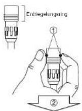
[AUFLADEN DES AKKUPACKS, DER AM FAHRRAD BEFESTIGT IST]
natural_image
Line drawing of a car viewed from above, showing front and side views (no text or symbols)27
A READ THIS MANUAL CAREFULLY! It contains important safety information.
Drive Unit
Display Unit
Battery Pack
Battery Charger
ORIGINAL INSTRUCTIONS
PW45

YAMAHA
TABLE OF CONTENTS
INTRODUCTION....1
LOCATION OF THE WARNING AND SPECIFICATION LABELS ....3
DESCRIPTION 5
E-BIKE SYSTEMS 6
SAFETY INFORMATION......9
INSTRUMENT AND CONTROL FUNCTIONS ....11
BATTERY PACK AND CHARGING PROCEDURE......21
CHECKING THE RESIDUAL BATTERY CAPACITY .....29
PRE-OPERATION CHECK....31
CLEANING AND STORAGE 32
TRANSPORT 34
CONSUMER INFORMATION ....35
TROUBLESHOOTING....36
SPECIFICATIONS ....41
52 - English English - 53
INTRODUCTION
These original instructions have been prepared for your Drive Unit, display unit, battery pack and battery charger.
FAILURE TO FOLLOW THE WARNINGS CONTAINED IN THIS MANUAL CAN RESULT IN SERIOUS INJURY OR DEATH.
Particularly important information is distinguished in this manual by the following notations:
| This is the safety alert symbol. It is used to alert you to potential personal injury hazards. Obey all safety messages that follow this symbol to avoid possible injury or death. | |
| A WARNING indicates a hazardous situation which, if not avoided, could result in death or serious injury. | |
| A NOTICE indicates special precautions that must be taken to avoid damage to the vehicle or other property. | |
| A TIP provides key information to make procedures easier or clearer. |
Indicates prohibited items that you must not do for safety reasons.
* Product and specifications are subject to change without notice.
INTRODUCTION
Please check your local riding laws and regulations before operating this e-Bike Systems bicycle.
Drive Unit, Display Unit,
Battery Pack, Battery Charger
ORIGINAL INSTRUCTIONS
©2015 by Yamaha Motor Co., Ltd.
1st edition, July 2015
All rights reserved.
Any reprinting or unauthorized use
without the written permission of
Yamaha Motor Co., Ltd.
is expressly prohibited.
Printed in Japan
54 - English English - 55
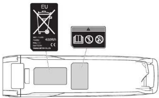
LOCATION OF THE WARNING AND SPECIFICATION LABELS
Read and understand all of the labels on your battery pack and battery charger. These labels contain important information for safe and proper operation. Never remove any labels from your battery pack and battery charger:
Battery pack
Battery charger
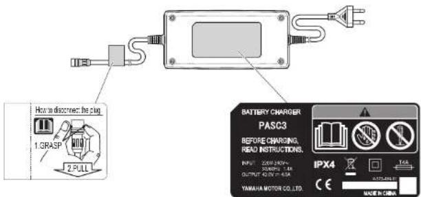
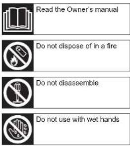
LOCATION OF THE WARNING AND SPECIFICATION LABELS
Familiarize yourself with the following pictograms and read the explanatory text, then make sure to check the pictograms that apply to your model.
56 - English English - 57
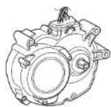
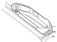
DESCRIPTION
1
2
natural_image
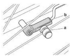
Technical diagram of a mechanical device with labeled parts (a and b), no readable text or symbols present.3
4
5
- Drive Unit
- Speed sensor set
a) Magnet sensor spoke type
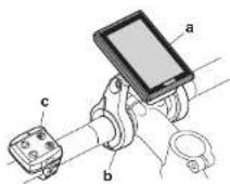
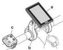
b) Pick up - Display unit
a) Display (detachable)
b) Display holder
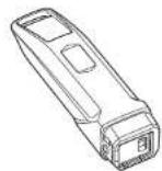
c) Switch - Battery pack
- Battery charger
5
E-BIKE SYSTEMS
The e-Bike Systems are designed to give you the optimal amount of power assist.
It assists you within a standard range based on factors such as your pedaling strength, bicycle speed, and current gear.
The e-Bike Systems do not operate in the following situations:
- When the display unit's power is off.
- When you are moving 45 km/h or faster.
- When you are not pedaling.
- When there is no residual battery capacity.
- When the automatic power off function* is operating.
* Power turns off automatically when you do not use the e-Bike Systems for 5 minutes.
- When the assist mode is set to Off mode.
- When the running assist switch is released.
- When the display unit is removed.
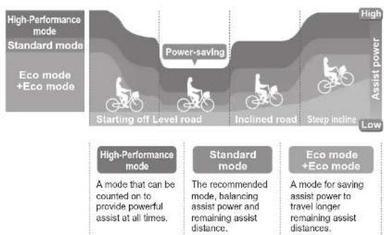
Four types of "assist mode" + Off mode are available.
Choose from High-Performance mode, Standard mode, Eco mode, +Eco mode and Off mode to suit your riding conditions. See "Displaying and switching the assist mode" for information on switching between assist modes.
| High-Performance mode | Use when you want to ride more comfortably, such as when climbing a steep hill. |
| Standard mode Use when riding on flat roads or climbing gentle hills. | |
| Eco mode+Eco mode | Use when you want to ride as far as possible. |
| Off mode | Use when you want to ride without power assist. You can still use the other display unit functions. |
6
58 - English English - 59
E-BIKE SYSTEMS
Power assist chart
flowchart
graph TD
    A["High-Performance mode\nStandard mode\nEco mode +Eco mode"] --> B["Starting off Level road"]
    B --> C["Power-saving"]
    C --> D["Inclined road"]
    D --> E["Steep incline"]
    E --> F["High\nAssist power\nLow"]

    G["High-Performance mode\nA mode that can be counted on to provide powerful assist at all times."] --> H["Standard mode\nThe recommended mode, balancing assist power and remaining assist distance."]
    H --> I["Eco mode +Eco mode\nA mode for saving assist power to travel longer remaining assist distances."]
- This illustration is for reference purposes only. Actual performance may vary depending on road conditions, wind, and other factors.
• In Off mode, power assist is not provided.
E-BIKE SYSTEMS
Conditions that could decrease remaining assist distance
The remaining assist distance will decrease when riding in the following conditions:
• Frequent starts and stops
• Numerous steep inclines
• Poor road surface conditions
- When carrying heavy loads
- When riding together with children
• Riding into a strong head wind
- Low air temperature
• Worn-out battery pack
- When using the headlight (applies only to models equipped with lights powered by the battery pack)
- Remaining assist distance will also decrease if the bicycle is not maintained properly.
Examples of inadequate maintenance that could decrease remaining assist distance:
- Low tire pressure
- Chain not turning smoothly
- Brake engaged constantly
SAFETY INFORMATION
Never use this battery charger to charge other electrical appliances.
Do not use any other charger or charging method to recharge the special batteries. Using any other charger could result in fire, explosion, or damage the batteries.
This battery charger can be used by children aged from 8 years and above and persons with reduced physical, sensory or mental capabilities or lack of experience and knowledge if they have been given supervision or instruction concerning use of the battery charger in a safe way and understand the hazards involved. Children shall not play with the battery charger. Cleaning and user maintenance shall not be made by children without supervision.
Although the battery charger is waterproof, never allow it to become immersed in water or other fluids. In addition, never use the battery charger if the terminals are wet.
Never handle the power plug, charge plug or touch the charger contacts with wet hands. This could result in electric shock.
Do not touch charger contacts with metallic objects. Do not allow foreign material to cause short circuit of the contacts. This could result in electric shock, fire, or damage the battery charger.
Periodically remove dust from the power plug. Dampness or other issues could reduce the effectiveness of the insulation, resulting in fire.
Never disassemble or modify the battery charger. This could result in fire or electric shock.
Do not use with a power strip or extension cord. Using a power strip or similar methods may exceed rated current and can result in fire.
Do not use with the cable tied or rolled up, and do not store with the cable wrapped around the charger main body. Cable damage can result in fire or electric shock.
Firmly insert the power plug and the charging plug into the socket. Failure to insert the power plug and the charging plug completely can result in fire caused by electric shock or overheating.
Do not use the battery charger near flammable material or gas. This could result in fire or explosion.
Never cover the battery charger or place other objects on top of it while charging. This could result in internal overheating leading to fire.
Do not touch the battery pack or battery charger while it is charging. As the battery pack or battery charger reaches 40–70 °C during charging, touching it could result in low-temperature burns.
Do not use if the battery pack case is damaged, cracked, or if you smell any unusual odors. Leaking battery fluid can cause serious injury.
SAFETY INFORMATION
Do not short the contacts of the battery pack. Doing so could cause the battery pack to become hot or catch fire, resulting in serious injury or property damage.
Do not disassemble or modify the battery pack. Doing so could cause the battery pack to become hot or catch fire, resulting in serious injury or property damage.
If the power cable is damaged, stop using the battery charger and have it inspected at an authorized dealer.
Do not turn the pedals or move the bicycle while the battery charger is connected. Doing so could cause the power cable to become tangled in the pedals, resulting in damage to the battery charger, power cable, and/or plug.
Handle the power cable with care. Connecting the battery charger from indoors while the bicycle is outdoors could result in the power cable becoming pinched and damaged in a doorway or window.
Do not run over the power cable or plug with the wheels of the bicycle. Doing so could result in damage to the power cable or plug.
Do not drop the battery pack or subject it to impact. Doing so could cause the battery pack to become hot or catch fire, resulting in serious injury or property damage.
Do not dispose of the battery pack in a fire or expose it to a heat source. Doing so could cause fire, or explosion, resulting in serious injury or property damage.
Do not modify or disassemble the e-Bike Systems. Do not install anything other than genuine parts and accessories. Doing so could result in product damage, malfunction, or increase your risk of injury.
When stopped, be sure to apply the front and rear brakes and keep both feet on the ground. Placing one's foot on the pedals when stopped may unintentionally engage the power assist function, which could result in loss of control and serious injury.
Do not ride the bicycle if there is any irregularity with the battery pack or e-Bike Systems. Doing so could lead to loss of control and serious injury.
Be sure to check the residual battery capacity before riding at night. The headlight powered by the battery pack will turn off soon after the residual battery capacity has decreased to where power assisted riding is no longer possible. Riding without an operating headlight can increase your risk of injury.
Do not start off by running with one foot on a pedal and one foot on the ground and then mounting the bicycle after it has reached a certain speed. Doing so could result in loss of control or serious injury. Be sure to start riding only after you are seated properly on the bicycle seat.
Do not press the running assist switch if the rear tire is off the ground. Otherwise, the tire will turn at high speed in the air and you could be injured.
Do not remove the display while riding the bicycle. Doing so will turn off the power assist, and could result in the bicycle falling over.
62 - English English - 63
INSTRUMENT AND CONTROL FUNCTIONS
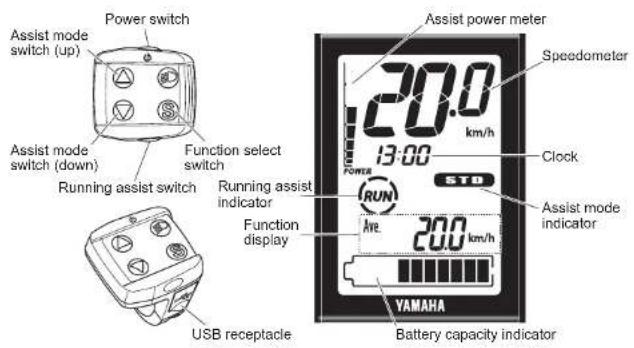
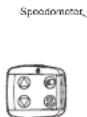
Display unit
TIP
"Switch does not function.
INSTRUMENT AND CONTROL FUNCTIONS
Display unit
The display unit offers the following operations and information displays.
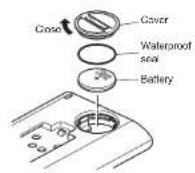
Battery
Check if the rated battery (CR2032) is installed in the rear of the display.
If a battery is not installed, or if there is not sufficient battery power remaining, install a new battery.
To adjust the time and set the units for distance and speed, see "Clock and km/mile settings".
TIP
• Make sure that the waterproof seal is installed correctly.
- Please use a new type CR2032 button cell battery (sold separately).
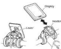
○ Mounting and removing the display
To mount the display, press the lever on the holder while sliding the display towards the rear of the bicycle into the holder. To remove the display, press the lever while sliding the display towards the front of the bicycle out of the holder.
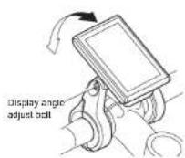
TIP
- Adjust the display angle by loosening the display angle adjust bolt. The angle depends on each rider.
- Make sure the display is turned off before mounting or removing it.
64 - English English - 65
INSTRUMENT AND CONTROL FUNCTIONS
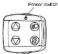
Power "On/Off"
Each time you press the power switch, the power switches between "On" and "Off".
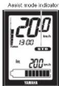
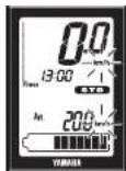
When you turn on the power, all of the displays light up. After that, the battery capacity indicator, speedometer, assist power meter, the function display such as average bicycle speed, and "STD" of assist mode indicator, and clock are displayed.
TIP
- When you turn on the power, the assist mode is automatically set to Standard mode.
- Keep your feet off the pedals when turning on the display unit. Also, do not start riding immediately after turning on the display unit. Doing so could weaken the assist power. (Weak assist power in either of these cases is not a malfunction.) If you did either of the above by accident, remove your feet from the pedals, turn on the power again, and wait a moment (approximately two seconds) before starting to ride.
INSTRUMENT AND CONTROL FUNCTIONS
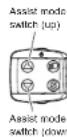
○ Displaying and switching the assist mode
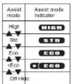
The assist mode indicator displays the selected assist mode.
- When you press the assist mode switch (up), the mode changes from "Off" to "+Eco" to "Eco" to "Std", or from "Std" to "High".
- When you press the assist mode switch (down), the mode changes from "High" to "Std", or from "Std" to "Eco", or "Eco" to "+Eco" or "+Eco" to "Off".
TIP
• Further pressing of the assist mode switch will not cycle the assist mode selections.
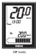
- In the Off mode, the assist mode and assist power meter are not displayed.
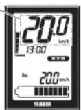
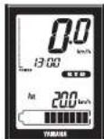
○ Speedometer
The speedometer displays your bicycle speed (in kilometer per hour or mile per hour). To select the km/mile, see "Clock and km/mile settings".
TIP
If your bicycle speed is less than 0.5 km/h or 0.3 MPH, the speedometer displays "0.0 km/h or 0.0 MPH".
66 - English English - 67
INSTRUMENT AND CONTROL FUNCTIONS
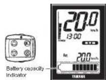
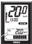
○ Battery capacity indicator
The battery capacity indicator displays an estimate of how much capacity is left in the battery on an 11-segment scale.
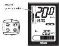
○ Assist power meter
The assist power meter displays an estimate of the assist power during riding on an 8-segment scale. When the e-Bike Systems are not in operation, none of the segments of the assist power meter are displayed. When the e-Bike Systems are operating, as the assist power increases, the segments of the assist power meter are added one by one.

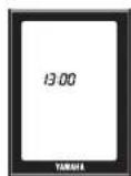
Clock
Displays the current time in 24 hour format. To adjust the time, see "Clock and km/mile settings". The time is displayed constantly, even when the display unit is turned off or removed from the holder.
INSTRUMENT AND CONTROL FUNCTIONS
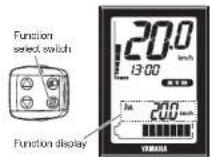
○ Function display
The function display can display the following functions.
• Average bicycle speed
• Maximum bicycle speed
- Trip meter
- Odometer
• Remaining assist distance
• Battery capacity (%)
- Cadence
Push the function select switch, the display changes as follows: Average bicycle speed → Maximum bicycle speed → Trip meter → Odometer → Remaining assist distance → Battery capacity (%) → Cadence → Average bicycle speed
You can reset the data for average bicycle speed, maximum bicycle speed and the trip meter by pressing the function select switch for 2 seconds or longer.
● Average bicycle speed
This displays the average bicycle speed (in kilometers per hour or miles per hour) since it was last reset. When you turn off the power, the data up to that point will remain in the display. To reset the data for the average bicycle speed, press the function select switch for 2 seconds or longer when the average bicycle speed is displayed.
● Maximum bicycle speed
This displays the maximum bicycle speed (in kilometers per hour or miles per hour) since it was last reset. When you turn off the power, the data up to that point will remain in the display. To reset the data for the maximum bicycle speed, press the function select switch for 2 seconds or longer when the maximum bicycle speed is displayed.
- Trip meter
This displays the total riding distance (in kilometers or miles) since it was last reset. When you turn off the power, the data up to that point will remain in the display. To reset the trip meter and begin counting a new total, press the function select switch for 2 seconds or longer when the trip meter is displayed.
- Odometer
This displays the total distance (in kilometers or miles) ridden while the power was on. The odometer cannot be reset.
68 - English English - 69
INSTRUMENT AND CONTROL FUNCTIONS
| DIST | 15_km | ● Remaining assist distanceThis displays an estimate of the distance (in kilometers or miles) that can be ridden with assist on the residual battery capacity of the battery installed. If you switch the assist mode when the remaining assist distance is displayed, the estimate of the distance that can be ridden with assist changes.The remaining assist distance estimate cannot be reset. |
| TIP____The remaining assist distance changes depending on the riding situation (hills, headwind, etc.) and as the battery runs down.If in “Off mode”, “----” is displayed. | ||
| 33% | ● Battery capacity (%)This displays the power remaining in the battery.The residual battery capacity display cannot be reset. | |
| 500rpm | ● CadenceThis displays your pedaling speed in revolutions per minute.The pedaling cadence display cannot be reset. | |
| TIP____If you pedal in backward, “0.0” is displayed. | ||
| ○ Running assistWhen you are on or off the bicycle and start moving it, you can use running assist without pedaling the bicycle.When you press the running assist switch once, the running assist indicator will come on for five seconds.Press and hold the running assist switch again while the indicator is still lit.Running assist will stop in the following situations:When you release the running assist switch.If you press another switch at the same time.When you start to pedal.If your bicycle speed exceeds the praset speed.If you select Off mode.If the wheels are not turning (when braking or coming into contact with an obstacle, etc.). |
INSTRUMENT AND CONTROL FUNCTIONS
| TIPThe maximum speed will vary depending on the selected gear. The maximum speed will become slower in a lower gear.Even if you release the running assist switch while the function is being used, the running assist indicator will remain on the display for five seconds.When you press and hold the running assist switch again while the indicator is lit, the running assist function will be available. | |
| Clock and km/mile settingsUse the following steps to set the time and km/mile settings.1. Make sure that the display is mounted on the display holder, and that the display unit is turned off.2. Press the power switch while holding the function select switch. | |
| When the "hour" on the clock begins to flash, release the switches.4. Use the assist mode switches (up & down) to set the "hour". | |
| Press the function select switch, and the "minutes" on the clock will begin to flash.Use the assist mode switches (up & down) to set the "hour". |
70 - English English - 71
INSTRUMENT AND CONTROL FUNCTIONS

- Press the function select switch, and the distance (km or mile) and speed (km/h or MPH) will begin to flash.
- Use the assist mode switches (up & down) to switch between "km & km/h" and 'mile & MPH'.

- Press the power switch. The settings are saved and this function is exited.

○ Diagnosis mode
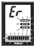
The e-Bike Systems are equipped with a diagnosis mode. When you turn on the power, if there is a malfunction or fault in the e-Bike Systems, the systems notify you of the fault by flashing the assist mode indicator and the battery capacity indicator alternately, and displaying "Er" in the speedometer. See "TROUBLESHOOTING" regarding symptoms and remedies for abnormal displays and abnormal flashing.
WARNING
If a fault is displayed, have your bicycle inspected by a dealer as soon as possible.
INSTRUMENT AND CONTROL FUNCTIONS
Power supply to external devices
Power can be supplied to most external devices (e.g. various smart phones etc.) by connecting a commercial USB cable.
[To supply power]
- Open the USB receptacle cap of the switch.
- Connect the USB cable to the switch and external device.
- Turn on the power of the vehicle.
[To stop the power supply]
- Turn off the power of the vehicle.
- Disconnect the USB cable and put on the cap of the USB receptacle.
NOTICE
- Do not apply unreasonable force on the USB plug or pull the USB cable.
- Check that the USB plug is facing the right way and not totally out-of-position with the USB receptacle or slanted, and make sure it is fully inserted all the way in.
- Do not connect the USB receptacle and the USB plug in a wet state.
- Use a USB cable that conforms to the standards.
- Do not insert foreign objects into the USB receptacle unit.
Otherwise the display unit and external device may malfunction.
TIP
• Power is supplied automatically when an external device is connected with the USB cable.
- No power is supplied if the remaining capacity of the battery pack is low.
- The power supply of the vehicle will go off and power supplied by the USB connection will also stop if the vehicle is not operated for 5 minutes.
72 - English English - 73
BATTERY PACK AND CHARGING PROCEDURE
The battery pack equipped for the Yamaha e-Bike Systems is a lithium-ion battery. The lithium-ion battery is lightweight and offers superior capacity. However, it does have the following characteristics.
- Its performance decreases in extremely hot or cold environments.
• It naturally loses its charge. - It is necessary to use it several times before its performance stabilizes.
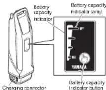
The battery pack for the Yamaha e-Bike Systems also has an embedded computer which notifies you of estimated residual battery capacity and suspected faults via the battery capacity indicator lamp.
By pressing the battery capacity indicator button, you can display the residual battery capacity for approximately 5 seconds.
See "CHECKING THE RESIDUAL BATTERY CAPACITY" for the estimate of the residual battery capacity. See "TROUBLESHOOTING" for information on fault flashing.
BATTERY PACK AND CHARGING PROCEDURE
Appropriate charging environments
For safe and efficient charging, use the battery charger in a location that is:
- Flat and stable (when on the bicycle)
• Free of rain or moisture
• Out of direct sunlight
• Well-ventilated and dry
• Not accessible to children or pets
• Temperature between 15–25 °C
Inappropriate charging environments and solutions.
The hot and cold environments described below can cause charging to enter standby or suspension without fully charging the battery.
• Summertime charging standby/suspension
If charging in a location receiving direct summer sunlight or immediately after riding, the battery charger might enter charging standby (all four battery capacity indicator lamps flash slowly). See "Reading the charging status". This is to automatically stop charging in order to protect the battery from exceeding the specified temperature while charging. You can avoid charging suspension by starting to charge with the battery cold or at a room temperature of 15–25 °C. If charging suspension occurs, move the battery charger to a cool location to reduce the charging standby time.
• Wintertime charging standby/suspension
Charging standby will occur if the temperature is 0 °C lower. If charging is started and the temperature drops below this level due to late-night cooling or other factors, charging is suspended and standby mode is entered to protect the battery. In such cases, restart charging at an indoor location with a temperature of 15–25 °C.
- Noise on televisions/radios/computers
Charging next to televisions, radios, or similar appliances might cause static, flickering images, and other interference. If this occurs, recharge in a location further away from the television or radio (such as in another room).
BATTERY PACK AND CHARGING PROCEDURE
WARNING
If a charging fault occurs during charging, remove the power plug of the battery charger from the socket and wait for the battery pack/battery charger to cool.
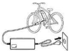
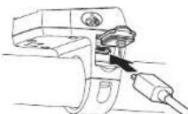
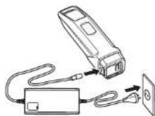
[CHARGING THE BATTERY PACK MOUNTED ON THE BICYCLE]
-
Connect the power plug of the battery charger to a household power outlet.
-
Remove the cap of charging inlet from the charging connector on the battery pack, and connect it to the charging plug on the battery charger.
NOTICE
- Do not connect the charging plug of the battery charger with the charging connector of the battery in a wet state.
- Be sure to connect the charging plug only after the charging connector on the battery pack is completely dry.
Otherwise the battery charger and battery may malfunction. - Do not apply excessive force to the charging plug or pull on the cord with the charging plug connected to the battery.
Otherwise, the plug or connector may be damaged.
- See "Reading the charging status", and check that the battery charger is charging the battery pack.
- The battery capacity indicator lamps will light up one by one until all four are on. Then, when charging is complete, all of the lamps will go off.
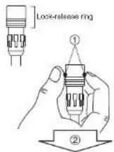
- Confirm that charging is complete, and then disconnect the charging plug from the battery pack.
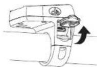
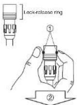
How to disconnect the plug (see the left figure)
① Grasp the lock-release ring.
② Pull it out straight. - Place the cap of charging inlet on the battery pack's charging connector.
WARNING
Never handle the power plug, charging plug or touch the charger contacts with wet hands. This could result in electric shock.
BATTERY PACK AND CHARGING PROCEDURE
TIP
- Charging will start automatically.
- If the display unit is turned on while the battery pack is charging, all normal displays will be shown, including the battery capacity indicator, but the assist system will not function.
- When the battery pack is connected to the battery charger, battery charger lamp will flash at approximately 0.2 second intervals to indicate that charging is preparing to charge the battery pack. Leave it as it is and charging will start normally.
[CHARGING THE BATTERY PACK REMOVED FROM THE BICYCLE]
- Turn the display unit off.
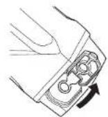
- Insert the key into the battery lock, and turn it clockwise to release the battery lock.
- Remove the battery pack.
WARNING
Use both hands when removing the battery pack, being careful not to drop it. Dropping the battery pack on your foot could result in injury.
-
Connect the power plug of the battery charger to a household power outlet.
-
Remove the cap from the charging connector on the battery pack, and connect it to the charging plug on the battery charger.
NOTICE
- Do not connect the charging plug of the battery charger with the charging connector of the battery in a wet state.
- Be sure to connect the charging plug only after the charging connector on the battery pack is completely dry.
Otherwise the battery charger and battery may malfunction. - Do not apply excessive force to the charging plug or pull on the cord with the charging plug connected to the battery.
Otherwise, the plug or connector may be damaged.
76 - English English - 77
BATTERY PACK AND CHARGING PROCEDURE
- See "Reading the charging status", and check that the battery charger is charging the battery pack.
- The battery capacity display lamps will light up one by one until all four are on. Then, when charging is complete, all of the lamps will go off.
- Confirm that charging is complete, and then disconnect the charging plug from the battery pack.
How to disconnect the plug (see the left figure)
① Grasp the lock-release ring.
② Pull it out straight.
9. Place the cap on the battery pack's charging connector.
- Mount the battery pack on the bicycle.
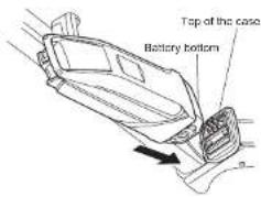
TIP
Mounting method of the battery pack
- Insert the battery in the direction of the arrow so that the battery bottom is aligned to the top of the case.
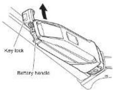
- Insert the upper part of the battery in the direction of the arrow so that the battery handle is aligned to the top of the key lock.
- Press the upper part of the battery toward the frame until it clicks into place to secure it.

natural_image
Line drawing of a car interior with lane markings (no text or symbols)BATTERY PACK AND CHARGING PROCEDURE
- Make sure that it is securely attached by pulling the battery after installation.
NOTICE
Make sure there is no foreign matter on the battery pack contacts before inserting the battery pack.
BATTERY PACK AND CHARGING PROCEDURE
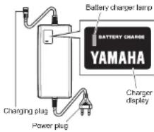
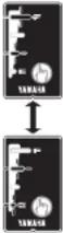
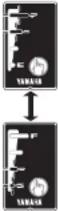
Reading the charging status
| Battery charger lamp | Battery capacity indicator lamps | Current status | Details |
| On | Lit power lamps indicate the amount of charging completed. A flashing power lamp indicates current progress.[20Y0](Example: Battery is approximately 50–75 % charged.) | Charging | During charging, the battery capacity indicator lamps light up one by one. |
| Off | [T4X0]Off | Charging completed | When charging is complete, the charging lamp on the battery charger and the battery capacity indicator lamp on the battery pack go off. |
Four lamps flash simultaneously. | Battery is in standby mode.* The battery internal temperature is too high or too low. | Charging will automatically restart when a temperature is reached that allows charging.(See “Appropriate charging environments”.)When possible, always perform charging at the optimal temperature of 15–25 °C. | |
| [32WC][IMAGE] | Battery is in fault mode. | There is a fault in the charging system. See “TROUBLESHOOTING.” |
BATTERY PACK AND CHARGING PROCEDURE
TIP
For example, even if normal charging is started, if the battery temperature or the surrounding temperature is too high or too low, the charging may be extended or charging may be stopped without the battery being charged sufficiently in order to protect the battery.
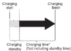
Charging time guidelines
Although charging time varies depending on residual battery capacity and external temperature, if the battery has been exhausted, it generally takes approximately 3.5 hours until one battery capacity indicator lamp flashes.
If the battery pack enters standby mode while charging, charging time will increase by an equal amount.
* If charging after a long period of disuse, the charging time will be lengthened depending on the battery status. However, note that if the battery capacity indicator lamps do not flash in fault pattern (See "Reading the charging status"), there is no malfunction.
CHECKING THE RESIDUAL BATTERY CAPACITY
You can check the estimate of how much capacity is left in the battery and to what extent it is charged. The check can be performed using either the display unit's residual battery capacity indicator or the battery's residual battery capacity indicator lamps.
TIP
- Even if the battery's capacity reaches 0 (zero), you can still ride the bicycle as a regular bicycle.
- If you are using an old battery pack, the residual battery capacity indicator may suddenly display very little power when you start moving. This is not a malfunction. Once riding stabilizes and the load is reduced, the proper value is displayed.
Residual battery capacity indicator display and estimate of residual battery capacity for display unit
The residual battery capacity can be displayed as a numerical value on the LCD display.
| Display of the residual battery capacity for the LCD multi-function drive controller | Display of the residual battery capacity | Applicable situation |
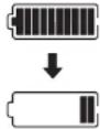 | 100–11 % | When you turn on the power of the LCD multi-function drive controller and ride continually after the battery is fully charged, the segments for the residual battery capacity indicator go out one by one each time the residual battery capacity is reduced by 10 %. |
 | 10–1 % | There is very little residual battery capacity left. Please charge the battery soon. |
 | 0 % | There is no more residual battery capacity. Turn off the power for the LCD multi-function drive controller and charge the battery pack soon.* Assist is stopped, but you can still ride the bicycle as a regular bicycle. |
CHECKING THE RESIDUAL BATTERY CAPACITY
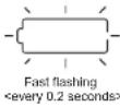
Display of the battery capacity indicator lamps and the estimate of the residual battery capacity
When checking the residual battery capacity, push the battery capacity indicator button "☐"
| Display of the battery capacity indicator lamps | Estimate of the residual battery capacity | Applicable situation | |
 | 100-76 % | From full charge (100 %), the battery capacity indicator lamps turn off, one by one. | |
 | 75-51 % | ||
 | 50-26 % | ||
 | 25-11 % | ||
 The bottom of lamp slow flashing<0.5 second interval> The bottom of lamp slow flashing<0.5 second interval> | 10-1 % There is very little battery capacity left. | ||
 The bottom of lamp fast flashing<0.2 second interval> The bottom of lamp fast flashing<0.2 second interval> | 0 % | The battery capacity has reached 0 (zero). Please charge the battery pack. | |
82 - English English - 83
PRE-OPERATION CHECK
WARNING
Be sure to perform the inspection before riding the bicycle.
If there is anything you do not understand or find difficult, please consult a bicycle dealer.
NOTICE
- If you confirm there is a fault, have your bicycle inspected at a dealer as soon as possible.
- The power assist mechanism consists of precision parts. Do not disassemble it.
Along with performing the regular inspection before riding the bicycle, also perform the following inspections.
| No. Inspection item Inspection contents | |
| 1 Residual battery capacity Is enough capacity left in the battery? | |
| 2 Installation status of the battery pack is it properly installed? | |
| 3 Operation of the e-Bike Systems | Do the e-Bike Systems operate when you begin moving? |
| 4 Display unit Is the display mounted correctly? | |
CLEANING AND STORAGE
NOTICE
Do not use high-pressure washers or steam jet cleaners since they can cause water seepage, resulting in property damage or malfunction of the Drive Unit or display unit or battery pack. Should water get inside one of these units, have an authorized dealer inspect your bicycle.
Caring for the battery pack
Use a moist, tightly-wrung towel to wipe off dirt on the battery case. Do not pour water directly on the battery pack, such as with a hose.
NOTICE
Do not clean the contacts by polishing them with a file or using a wire, etc. Doing so could result in a fault.
Storage
Store the system in a place that is:
- Flat and stable
• Well ventilated and free from moisture - Sheltered from the elements and from direct sunlight
CLEANING AND STORAGE
Long storage period (1 month or longer) and using it again after a long storage period
- When storing the bicycle for a long period (1 month or longer), remove the battery pack and store it using the following procedure.
- Decrease the residual battery capacity to where one or two lamps are lit, and store it indoors in a cool (10 to 20 °C), dry place.
- Check the residual battery capacity once a month, and if only one lamp is flashing, charge the battery pack for about 10 minutes. Do not let the residual battery capacity become too low.
TIP
- If you leave the battery pack at "full charge" or "empty", it will deteriorate quicker.
- Due to self-discharge, the battery slowly loses its charge during storage.
- The battery's capacity decreases over time but proper storage will maximize its service life.
- When using it again after a long storage period, be sure to charge the battery pack before using it. Also, if you are using it again after storing it for 6 months or longer, have your bicycle inspected and maintained at a dealer.
TRANSPORT
The batteries are subject to the Dangerous Goods Legislation requirements. When being transported by third parties (e.g. via air transport or forwarding agency), special requirements on packaging and labels must be observed. To prepare the item for shipping, consult a hazardous materials expert. The customer can transport the batteries by road without further requirements. Do not transport damaged batteries.
Tape or mask off open contacts and pack up the battery pack in such a manner that it cannot move around in the packaging. Be sure to observe all local and national regulations. In case of questions concerning transport of the batteries, please refer to an authorized bicycle dealer.
CONSUMER INFORMATION

Disposal
The Drive Unit, battery pack, battery charger, display unit, speed sensor set, accessories and packaging should be sorted for environmental-friendly recycling. Do not dispose of the bicycle or its components as household waste.
For EU countries:
According to the European Guideline 2012/19/EU, electrical devices/tools that are no longer usable, and according to the European Guideline 2006/66/EC, defective or used battery packs/batteries, must be collected separately and disposed of in an environmentally correct manner. Please return battery packs that are no longer usable to an authorized bicycle dealer.
TROUBLESHOOTING
E-Bike Systems
| Symptom Check | Action | |
| Pedaling is difficult. | Is the display unit's power on? | Press the power switch on the display unit to turn the power on. |
| Is the battery pack installed? | Install a charged battery pack. | |
| Is the battery pack charged? | Charge the battery pack. | |
| Has the bicycle remained stationary for 5 minutes or longer? | Turn the power on again. | |
| Are you riding on a long inclined road or carrying a heavy load during summertime? | This is not a malfunction. It is a safeguard engaged when the temperature of the battery pack or the Drive Unit is too high. Power assist will be restored once the temperature of the battery pack or the Drive Unit has decreased. Also, you can make this less likely to occur by shifting to a lower gear than you would usually use (for example, by shifting from second to first gear). | |
| Is the air temperature low (roughly 10 °C or below)? | During the wintertime, store the battery pack indoors before use. | |
| Is the display set correctly? | Set the display correctly. | |
| Are you charging the battery pack while it is mounted on the bicycle? | Stop charging the battery pack. | |
| The Drive Unit turns on and off while riding. | Is the battery pack correctly installed? | Check to make sure the battery pack is locked in place.If this problem still occurs with the battery pack firmly locked in place, there may be a loose connection the battery pack terminals or wires. Have an authorized dealer inspect your bicycle. |
| Strange rumbling or crunching noises come from the Drive Unit. | There could be a problem inside the Drive Unit. | |
| Smoke or unusual odor comes from the Drive Unit. | There could be a problem inside the Drive Unit. |
88 - English English - 89
TROUBLESHOOTING
| Symptom Check | Action | |
The speedometer displays “Er”.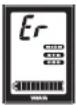 | There could be a problem inside the Drive Unit is malfunctioning.Turn on the power to the display unit and then leave it alone for 5 minutes. All indicators will turn off automatically.Turn the power on again. | |
The assist mode indicator and battery capacity indicator flash rapidly alternately.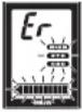 | ||
| The display unit shuts down immediately (approx. 4 seconds later) after switching the power on. | Are the bicycle's battery pack connection terminals dirty? | Remove the battery pack, clean the bicycle's terminals with a dry cloth or cotton swab, and then install the battery pack again. |
| Traveling range has decreased. | Are you fully charging the battery pack? | Charge the battery pack until full (F). |
| Are you using the system under low-temperature conditions? | Normal traveling range will be restored when the ambient temperature rises.Additionally, storing the battery pack indoors (in a warm location) before use will improve traveling range under cold conditions. | |
| Is the battery pack worn out? | Replace the battery pack. | |
The assist mode Indicators are flashing. | These indicators will flash when the speed sensor is unable to detect a correct signal.Turn off the power to the display unit and then turn it on again, select the assist mode and then ride for a short distance.Also, make sure the magnet is mounted correctly on the spokes of the wheels. |
TROUBLESHOOTING
| Running assist function | ||
| Symptom Check | Action | |
| The running assist function does not work. | When you press the running assist switch once, the running assist indicator will come on for five seconds.Press and hold the running assist switch again while the running assist indicator is still lit. | |
| The running assist function turns off. | Did the tires lock for a few seconds? | Remove your finger from the running assist switch for a moment, and then operate the running assist function again. |
| Did you pedal while the running assist function was running? | Take your feet off the pedals, and remove your finger from the running assist switch for a moment, and then operate the running assist function again. | |
Power supply of external devices via USB connection
| Symptom Check | Action | |
| Power is not supplied. | Is the display unit's power on? | Press the power switch on the display unit to turn the power on. |
| Is the USB version correct? | Use an external device that complies with USB 2.0. | |
| Is the USB cable firmly connected? | Re-connect the USB cable. | |
| Is the USB receptacle or USB plug terminal dirty or wet? | Disconnect the USB cable from the display unit and external device. Remove the dirt and water on the USB receptacle and USB plug terminal and re-connect the cable. |
TROUBLESHOOTING
Battery pack and charger
| Symptom Check | Action | ||
| Cannot charge | Is the power plug firmly connected? Is the charging plug firmly inserted in the battery pack? | Reconnect and try charging again. If the battery pack still does not charge, the battery charger might be malfunctioning. | |
| Are the residual battery capacity lamps lit? | Review charging method and try charging again. If the battery pack still does not charge, the battery charger might be malfunctioning. | ||
| Are the battery charger or battery pack contact terminals dirty or wet? | Remove the battery pack from the battery charger and the charger plug from the socket. Use a dry cloth or cotton swab to clean the charger and battery contact terminals, and then reconnect. | ||
 | There is a contact fault in the contact terminals. | Remove the battery pack from the bicycle, connect the charging plug into the battery pack. (If lamps still flash alternately, there might be a fault in the battery pack) When remount the battery pack on the bicycle and press the power switch of display unit, if lamps still flash alternately, there might be a fault in the Drive Unit. | |
 | There is a contact fault in the contact terminals. | Remove the battery pack from the battery charger, mount the battery on the bicycle and press the power switch of display unit. When the charging plug reconnected into the battery pack, if lamps still flash simultaneously, there might be a fault in the battery charger. | |
| Isn't the charging connector on the battery pack wet? | Clean the charging connector and charging plug, and dry them. After that, connect the charging plug to the charging connector. | ||
TROUBLESHOOTING
| Symptom Check | Action | |
| Both side lamps are flashing simultaneously. [TSTC] | The battery pack protection feature has been activated and the system cannot be used. Replace the battery pack at an authorized dealer as soon as possible. | |
| The battery charger emits abnormal noises, foul odors or smoke. | Unplug the charger plug and immediately cease operation. | |
| The battery charger becomes hot. | It is normal for the battery charger to become somewhat warm during charging. | If the battery charger is too hot to be touched by hand, unplug the charger plug, wait for it to cool, and consult an authorized dealer. |
| After charging, all of the battery capacity indicator lamps do not light up when the battery capacity indicator button “D” is pressed. | Has the charger plug been unplugged or the battery pack removed during charging? | Charge the battery pack again. |
| Did you start charging with the battery pack at a high temperature, such as immediately after use? | Move to a location where the battery temperature can reach the range where charging is possible (0–30 °C), and then start charging again. | |
| After disconnecting the charging plug on the battery charger from the battery pack, the battery capacity indicator lamps continue to light. | Isn’t the charging connector on the battery pack wet? | Clean the charging connector and charging plug, and dry them. |
SPECIFICATIONS
| Range of assist speed 0 to less than 45 km/h | ||
| Electric motor | Type Brushless DC type | |
| Power 500 W | ||
| Assist power control method | Control method depends on pedaling torque and bicycle speed | |
| Battery | Type | PASB2(Lithium-ion battery) |
| Rated voltage 36 V | ||
| Rated capacity 11 Ah | ||
| Number of battery cells 40 | ||
| Charger | Type PASC3 | |
| Input voltage AC 220 | -240 V/50–60 Hz | |
| Maximum output voltage DC 42 V | ||
| Maximum output current DC 4.0 A | ||
| Maximum consumed power | 310 VA/180 W(Charged at AC 240 V) | |
| Applicable type battery PASB2 | ||
| Display unit(Power supply portion) | USB receptacle type USB 2.0 Micro-B | |
| Output current Max. 500 mA | ||
| Rated voltage 5 V | ||

YAMAHA
natural_image
Technical diagram of a mechanical assembly with labeled parts (a and b), no readable text or symbols present.3
4

5

Mode Haute performance
m = 311
- 第 1
Amchage
natural_image
Diagram showing a bicycle connected to an electrical plug and its cable, with a close-up of the cable being inserted (no text or symbols present)[CHARGER LE BLOC-BATTERIE INSTALLÉ SUR LE VÉLO]
① Salsissez la bague lock-release.
natural_image
Line drawing of a car in motion, showing forward and rear views (no text or symbols)126 - Français Français - 127
BLOC-BATTERIE ET PROCÉDURE DE CHARGE
- Model overview and max. permissible total weight for model year 2016
- Definition
- S-Pedelec: Legal and technical information
- Speed Pedelec (short S-Pedelec) or Speed EPAC:
- Legal information
- Present situation: March 2016
- Difference between a „normal“ Pedelec / Bicycle and a S-Pedelec
- Liability insurance
- Insurance tag
- Authorisation requirement & license plate
- CoC document / EG declaration of compliance
- Non EU countries
- Classification of the S-Pedelec as motor assisted bicycle (moped)
- Driver's license, cycle tracks, helmet compulsory
- Roads closed for motor vehicles
- Transport of children / goods with a S-Pedelc of Winora Staiger GmbH
- Minimum tread depth
- Technical information
- Type approval and jurdistiction
- Specialities of certain components of the motor vehicle S-Pedelec in comparison to conventional pedelec / bicycle components
- frame / fork
- licence plate holder
- rear view mirror
- brake lever
- stand
- lateral reflectors
- brake light
- licence plate lighting
- daytime running light / continuous lighting
- tyres
- Structural changes on your S-Pedelec
- Approval of alternative components by Winora-Staiger GmbH
- Homologation & immatriculation
- TABLE OF CONTENTS
- INTRODUCTION
- LOCATION OF THE WARNING AND SPECIFICATION LABELS
- DESCRIPTION
- E-BIKE SYSTEMS
- Conditions that could decrease remaining assist distance
- SAFETY INFORMATION
- INSTRUMENT AND CONTROL FUNCTIONS
- Display unit
- Battery
- TIP
- ○ Mounting and removing the display
- Power "On/Off"
- ○ Displaying and switching the assist mode
- ○ Speedometer
- ○ Battery capacity indicator
- ○ Assist power meter
- Clock
- ○ Function display
- ● Average bicycle speed
- ● Maximum bicycle speed
- - Trip meter
- - Odometer
- ○ Diagnosis mode
- WARNING
- Power supply to external devices
- [To supply power]
- [To stop the power supply]
- NOTICE
- BATTERY PACK AND CHARGING PROCEDURE
- Appropriate charging environments
- Inappropriate charging environments and solutions.
- [CHARGING THE BATTERY PACK MOUNTED ON THE BICYCLE]
- [CHARGING THE BATTERY PACK REMOVED FROM THE BICYCLE]
- Charging time guidelines
- CHECKING THE RESIDUAL BATTERY CAPACITY
- Residual battery capacity indicator display and estimate of residual battery capacity for display unit
- Display of the battery capacity indicator lamps and the estimate of the residual battery capacity
- PRE-OPERATION CHECK
- CLEANING AND STORAGE
- Caring for the battery pack
- Storage
- Long storage period (1 month or longer) and using it again after a long storage period
- TRANSPORT
- CONSUMER INFORMATION
- Disposal
- For EU countries:
- TROUBLESHOOTING
- YAMAHA
- Mode Haute performance
- [CHARGER LE BLOC-BATTERIE INSTALLÉ SUR LE VÉLO]
- BLOC-BATTERIE ET PROCÉDURE DE CHARGE
Brand : YAMAHA
Model : PW45
Category : Electric bike