
EFLE61 - Optical adjustment device BOSCH - Free user manual and instructions
Find the device manual for free EFLE61 BOSCH in PDF.

| Product type | Optical adjustment device (mobile headlight adjuster) |
| Brand | Bosch |
| Model | EFLE61 |
| Main functions | Alignment of headlights along the vehicle's longitudinal axis, adjustment of beam inclination, measurement of illuminance (lux meter) |
| Power supply | Manual (no external power source) |
| Dimensions (approx.) | Adjustable height, lens about 30 cm from the headlight |
| Weight | Not specified, transportable on wheels |
| Maintenance and cleaning | Clean the lens and mirror with a soft cloth; lubricate the wheels occasionally with a few drops of oil; keep the guide column dry and free of grease |
| Safety | Protect from shocks, handle with care; regularly check measurement accuracy |
| Spare parts and repairability | Maintenance contract recommended with a Bosch service point |
| General information | Used for vehicle headlight adjustment in accordance with legal requirements; available in mobile version (EFLE61) or on rails (EFLE62) |
Frequently Asked Questions - EFLE61 BOSCH
User questions about EFLE61 BOSCH
0 question about this device. Answer the ones you know or ask your own.
Ask a new question about this device
Download the instructions for your Optical adjustment device in PDF format for free! Find your manual EFLE61 - BOSCH and take your electronic device back in hand. On this page are published all the documents necessary for the use of your device. EFLE61 by BOSCH.
USER MANUAL EFLE61 BOSCH
Headlight Aiming Device EFLE 50..52/60..62
Régophare EFLE 50..52/60..62
Alineador de faros EFLE 50..52/60..62
Instructions for putting into operation 9
- General 9
1.1 Mobile headlight aiming devices EFLE 50, EFLE 51, EFLE 60 and 61 9
1.2 Headlight aiming device on floor rails EFLE 52 and EFLE 62 10 - Prerequisites for aiming the headlamps 10
2.1 Operating site 10
2.2 Tire-inflation pressure 10
2.3 Headlamps 10
2.4 Setting up aiming device 11
2.5 Aligning the aiming device with the longitudinal axis of the vehicle 11
2.6 Adjusting the aiming device 11 - Aiming regulations 11
4.Measuring images 12
4.1 Headlamps with asymmetrical lower beam 12
4.2 Headlamps with symmetrical lower beam, and fog lamps 12
4.3 Headlamps with inclination data 12 - Luxmeter 13
- Maintenance and care 13
Page
Indice Pagina
Instructions for putting into operation
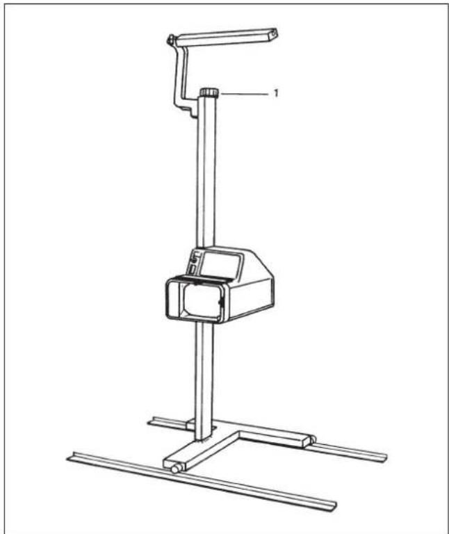
Before the headlight aiming device is put into initial operation the alignment mirror and the handle on EFLE 50, 51, 60 and 61 must be turned to the working position.
Operations required to do this
Release the locking screw (1) on the equipment support column using a 4mm hexagon-socket screw key.
- Swing the arm holding the alignment mirror 180° upward (2).
Tighten the locking screw again.
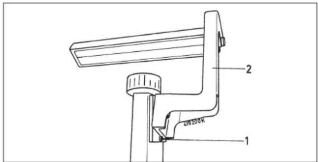
Fig. 1
Operations required to do this
Release the locking screw (1) on the equipment support column using a 5mm hexagon-socket screw key.
- Swing the handle 90° outwards.
- Insert the locking screw in the hole and tighten.
Fig. 1a
1. General
Headlamps on motor vehicles must not blind the drivers of vehicles coming from the opposite direction. The inclination and the aiming of the headlamp light beam to the side must therefore be adjusted according to legal specifications.
In order to make these legally specified adjustments of motor-vehicle headlamps, Bosch supplies the following aiming devices:
1.1 Mobile headlight aiming devices EFLE 50,EFLE 51,EFLE 60 and 61
The surface on which the headlight aiming device is set up must be even but it does not have to be horizontal. In order to achieve the specified measurement accuracy, surface irregularities within the area where the aiming device is used must be less than 1.2mm
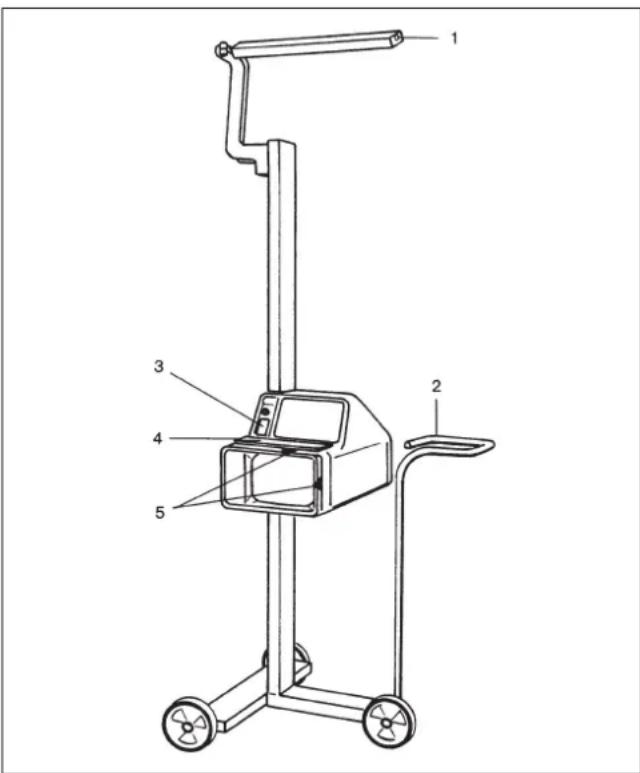
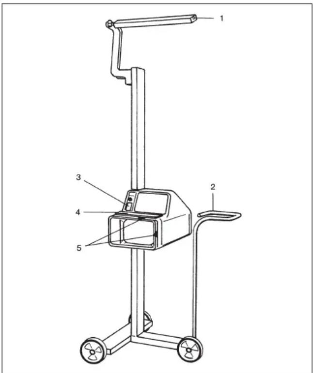
Fig. 2
1 alignment mirror
2 handle
3 luxmeter
4 deflection mirror
5 markings for lens center
1.2 Headlight aiming device on floor rails EFLE 52 and EFLE 62
The standing surface for the vehicle and the guide rails of the apparatus must be horizontal and parallel to one aonther. In order to achieve the prescribed measuring exactness, the horizontal deviation of the guide rails must not be more than 1.3mm out of line with respect to one another.
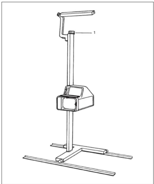
Fig. 3
1 Roatary knob for aligning the test device with the longitudinal axis of the vehicle.
2. Prerequisites for aiming the headlamps
2.1 Operating site
The operating site must meet the conditions specified in Sections 1.1 and 1.2 above.
2.2 Tire-inflation pressure
All tires must be inflated to the pressure specified for the particular vehicle.
2.3 Headlamps
Deflective lenses and reflectors, as well as blackened bulbs must be replaced before the aiming adjustment.
With headlamps that are fitted with an adjusting device, observe the following:
In order to aim headlamps on vehicles fitted with a device for infinitely variable adjustment of the headlamps by hand, the adjusting device must be in the specified detent position.
When the headlamps are fitted with an adjusting device that can be set to only 2 detent positions, proceed as follows:
- With vehicles in which the headlamp beams are directed upward as the load increases (loading space at the black), the headlamps should be aimed with the adjusting device in the "high" lightbeam detent position.
- With vehicles in which the headlamp beams are directed downward as the load increases (loading space at the front), the headlamps should be aimed with the adjusting device in the "low" light-beam detent position.
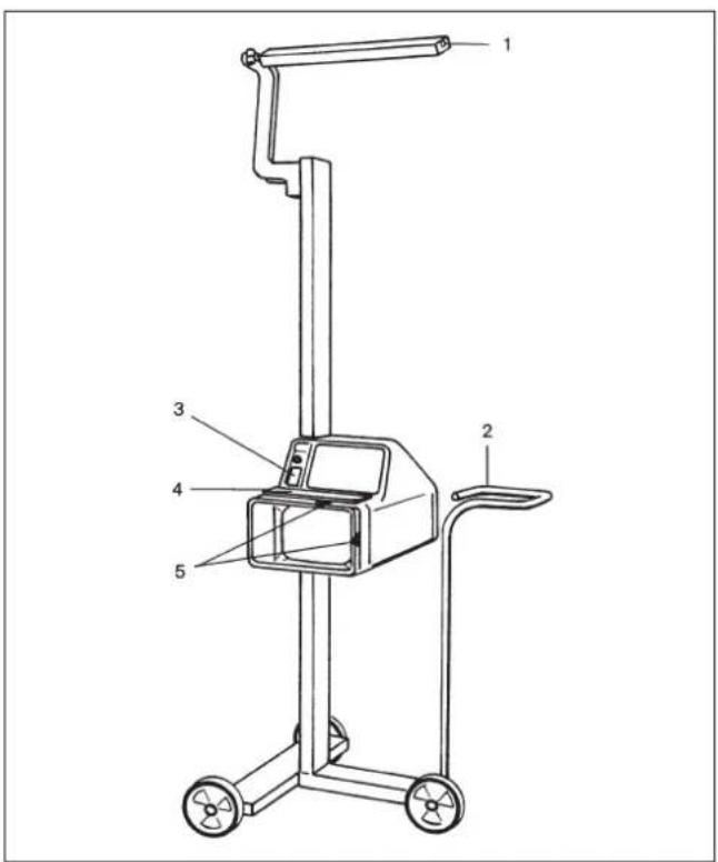
2.4 Setting up aiming device
The distance between the aiming device and the headlamp should be just enough so that setting operations can also be carried out on the headlamp from in front (about 30 cm ).
The center of the lens on the aiming device should differ by less than 3cm from the headlamp center. The center of the lens is identified by marks (see Fig. 2, No. 5).
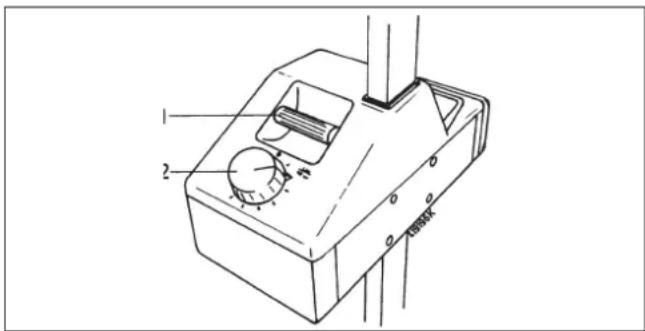
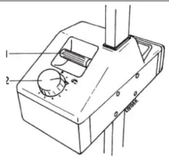
In order to adjust the height of the aiming device, the hand roller ist turned (1) and a brake is released. The brake automatically looks in place again when the roller is released.
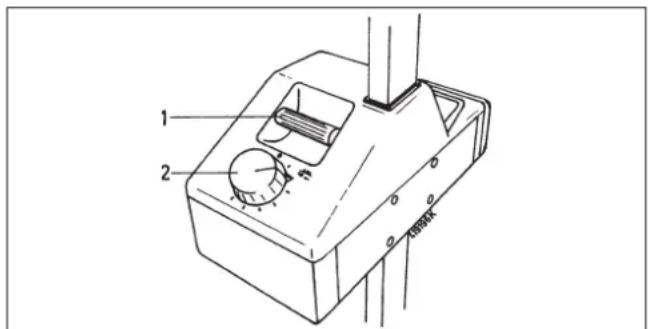
Fig. 4
1 control knob for height adjustment
2 rotary knob for setting the inclination measure
2.5 Aligning the aiming device with the longitudinal axis of the vehicle
2.5.1 Vehicles with flat engine-compartment lid
By swinging the mirror arm (Fig. 1, Pos. 2) the alignment mirror (Fig. 2, Pos. 1) is set above the head towards the operator so that the front of the vehicle with two outer symmetrical reference points (for example, the upper edge of the headlamps, joints in the engine hood, etc.) are visible in it.
The aiming device is aligned on the longitudinal axis of the vehicle so that the positioning line on the mirror touches these two outer reference points equally (see Fig. 5).
With the mobile aiming devices (EFLE 50, 51, 60 and 61), this is done by moving the aiming device using the wheeling handle.
The floor-rail aiming device (EFLE 52 and 62) is turned as required with the rotary knob at the top of the support column (Fig. 3, No. 1).
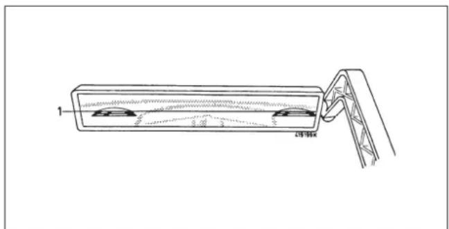
Fig. 5
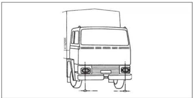
2.5.2 Cab-over-engine vehicles
In vehicles with vertical front section the centres of the headlights are marked with chalk on the floor using a plumb bob. The centres can be connected with a rail. These markings are lined up in the adjusting mirror.
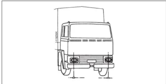
Fig. 6
2.6 Adjusting the aiming device
The setting used for aiming headlamps is the inclination value in cm which the cut-off must have at a distance of 10m
This setting is given in Section 3.1, and is made before the test at the rotary knob (Fig. 4, No. 2).
The vehicle should be loaded as specified.
3. Aiming regulations
Please observe the aiming regulations valid in your country.
4. Measuring images
The measuring images can also be observed from the rear of the aiming device by means of the deflection mirror (Fig. 10, No. 3).
Before every measurement the prerequisites given in Section 2 above must be complied with.
4.1 Headlamps with asymmetrical lower beam
With headlamps used for an asymmetrical lower beam, the lower beam cut-off line must coincide with the boundary line to the left of the center point. The point of intersection between the left-hand part of the lower beam cut-off line (as horizontal as possible) and the right-hand rising part of this line must be located on the vertical line that passes through the center mark. In order to determine this point of intersection more easily, the left-hand half of the handlamp can be alternately masked and unmasked serveral times.
After the lower beam cut-off line has been set according to specifications, the center of the high beam with headlamps on which the lower beam and upper beam can be aimed together must lie within the limit corners inscribed around the center mark.
With high-beam headlamps fitted with their own adjustment mechanisms, the center of the light beam must be positioned on the center mark.
4.2 Headlamps with symmetrical lower beam, and fog lamps
With headlamps used for a symmetrical lower beam and with fog lamps, the highest part of the lower beam cut-off line must touch the boundary line, must be as horizontal as possible across the width of the test surface.
To the side, these headlamps must be aimed so that the distribution of the light is as symmetrical as possible with respect to the vertical line that passes through the center mark.
After the lower beam cut-off line has been set according to specifications, the center of the high beam with headlamps on which the lower beam and upper beam can be aimed together must lie within the limit corners inscribed around the center mark (see Fig. 8).
With high-beam headlamps fitted with their own adjustment mechanisms, the center of the light beam must be positioned on the center mark (see Fig. 8).
Example: Boundary line for the lower eam cut-off with an asymmetrical lower beam.
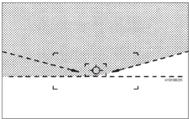
Fig. 7
Example: Center mark and boundary corners for the center of the higt beam.
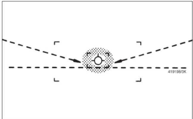
Fig. 8
Example: Boundary line for the lower beam cut-off with a symmetrical lower beam and with fog lamps.
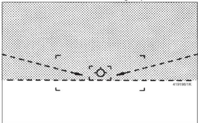
Fig. 9
4.3 Headlamps with inclination data
In the case of single-axle towing vehicles or machines with headlamps permanently set to the lower beam and on which the inclination of the light beam center is given, the center of the beam must lie on the boundary line and on the vertical line that passes through the center mark.
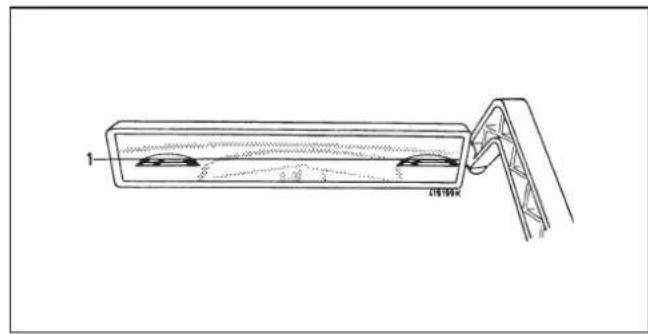
5. Luxmeter
Using the luxmeter, the illumination from the headlamps can be tested (measured) after they have been aimed.
During these tests the rotary knob for the setting must always be set to the position 10cm / 10m
Lower beam: The illumination must be below the permissible glare value. Press the pushbutton on the luxmeter. The pointer must remain within the green range on the scale marked "A".
High beam: The illumination must reach the minimum permissible value. The pointer must come up to the green range on the德拉 marked "F".
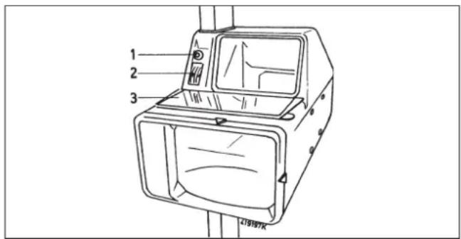
Fig. 10
1 Push button for luxmeter
2 Scale for luxmeter
3 Deflection mirror
6. Maintenance and care
The headlight aiming device is a high-precision optical measuring instrument. In order to preserve its measurement accuracy, shocks and rough handling must be avoided.
At regular intervals its accuracy is to be checked.
This is especially important for workshops which carry out their work according to legal regulations.
For this purpose we recommend that a maintenance contract be concluded with the responsible Bosch Customer Service. This will ensure that the aiming device will be checked and tested by trained personnel using the right test equipment and according to plant specifications.
For maintenance purposes the wheels should be lubricated occasionally with a few drops of oil.
The support column must be kept dry and free of grease and oil!
Wipe the lens and the reflector with a soft cloth to keep them clean.
MeCTO yCTaHOBKn DOJXHO 6bITb POBHbIM, HO He o6raTeJIbHO rOpI3OHTaJIbHbIM. Yo6bIOCTnY ppeINcAHHO TOHOCTN I3MepEnH, HEPOBHOCTN IOna B MeCTe YCTaHOBKn Pnp6opa DoJXHbI 6bITb MeHee Yem 1,2 MM.
Pnc.2
- BbipaaHueaiouee 3epkaIoo
2.Диuaioua pyka - JIOKcMemp (U3mepumelb cunblcema)
4.Поворомhoe3epkaJIO - Ommemku dna cepedu hbu nH3bI
Y φap c yctpoiCTBOM peRyIINpOBKn HxKHO yHNTbIBaTb:
Длгpeулровкфapу aBTOMobилeи,y KOToPbIXфapblMOrYT BpyHyU 6e3ctypeHcatopeylnpoBaTbcR,yCTpOiCTBO peylnpoBKNdoJXHO HaxoDITbcR BпрдпсанHomФнКсрOBaHHOM nIoKxeHn.
Y φap c perylnpoBOHbIM yCTpOiCTBOM TOIbKO Ha 2 NOJoxEHHa, HxKHO DeiCTBOBaTb CNeDyUOIM O6pa3OM:
-yaBTOMO6HJEn,yKOTOpbIXIyOcCBeTa
PnHaRpyKeHNIOHnMaetc
(6araXnKc3aDn),HyXHO pOBODITb
peYIpOBKy B KOHeuHOM INoJOxEHN
peYIpOBoOHOrO yCTpOiCTBa,pi
KOTOPM NyOK CBeTa HaxOHTCBA
HAHBbICUeM INoJOxEHN.
-y aBTOMO6nJIeN, y KOTOpbIX NyUOK CBeta npn HargyuKeHnn aBTOMo6nIa onyckaetcra (6araXnK cnepei) peYIpOBky HxKnHO IpBOOHTb B KOHeuHOM IonoJKeHnn peYIpOBoCHoro ycTPOIcTBa, npn KOTOpom NyUOK CBeta HaxOJNTcB HxKHom IonoJKeHnn.
2.4. YcTaHOBKa np6Opa dJa npoBepKn
PacctoarHne MeJxdy npnbopom n fapamn DoJIxHO 6bITb TaKIM, YTO6bI C fapamM MoXHO 6blIO npOIN3BOIDITb peRyINpOBOCHbIE pa60tbl cpepei (np6bn. 30 cm). CepeHa JInH3bl np6bopa He DOJXHa OTKIOHrTbcr OT φap 60JIbSe yem Ha 3 cm. OHa o6o3Haayetcra OTMeTKaMn Ha np6bope (cm. Pnc.2, Po3.5).
Pnc.2
Дя yctaHOBK BbICOTbI npn OTbOpaUNBaHN pyuKn OCBO6OxJaETcra TopMo3 (cm. Pnc.4, Po3.1), KOTpbI npn OTnyckAHn pyuKn 3akpePJIeTcra camOCToTeJIbHO.
2.5. BbipabHnBaHne npnbopa dny npOBepKn no OTHOseHnK npoJoIbHoJ OCN aBTOMo6nJIa
2.5.1.ABtOMo6nJIn cPoBHBIM KaIOTOM
BbipabHnBaUoee 3epKaI0 (Pnc.2 P03.1) ycTaHaBnBaETCa Hnd rOIOBOI o6cnyKnaBoUeTo nepcoHajn nyTeM noBOpota pykaba 3epkana (Pnc.1 P03.2) TaKIM o6pa3OM, YTO6bl B 3epkane npocMaTpRuBaJacb NpeDnJa YAcTb aBTOMOBnJIc DvByMa CmmMeTpNHyBMn ChapyKn JexKaUHMN OTMeTKaMn (HaNPmEp, BepxHra OKaHTOBKa fap, BbiTuAMNoBka Ha KpbIuKe KaNoTa).
Pnp6op dIpy npOBepKn BbipaBHNBaETcR B npOIOJbHOM HAppaBJIeHnn ABTOMO6nJIra TaKIM o6pa3OM, yTo6bl IINHna 3epKaJa npoxoJnla chepe3 DBe HapyKhble OTMeTKN (cm.Pnc.5)
Pnc.5
2.5.2.ABtOMo6nHcKa6HOnHaNnI nped DBrataTeIeM (Pnc.6)
Y aBTOMOBnne C BbICOKO BEpTKaJIbHOI NaHeJIbIO cepeINHbI fap BbIEuINBaIOTcC NOMOuTOB OTBeCOB Ha IOnI N TaM OTMeuAOTcMeIOM. OTMeKIN Bu3NpyIOTcC NOMOuBu BBipABHnBaHOUe 3epKaJa.
Y nepeDbNkHbIX npnbopOB dIy npOBepKn EFLE 50, 51, 60 n 61 3To doCTnraetcnyTeM nepeDbNkeHn npnbopa npn nomoun DnurraHoue pyKn.
Y npnbopOB Ha peIbcax (EFLE 52 n 62) cam npnbop COOTBETCTBEHNO Bpaauaetc npn nomouu noBOPoTHo KNOpKn (Pnc.3, P03.1) Ha cToiKe.
Pnc.6
Pnc.3
2.6. Hac tropona npnbopa
Iapametpom peryunipOBKn dIa fap
YBJIeTcna Iapametp HaKIOHa B CM., KOTOpbI
DOJKeH IMeTb rpaHnCy CBET/TeHb B 10 M.
OTdAJIeHnI.
Iapametp perynipOBKn BndeH n3 pa3dena 3.1. n HactpanBaetcpeep npOBepko IOBopoTHo KHOKoi np6opa (Pnc.4, Pno3.2)
Pnc.4
AByOmbHarpy3ntB CootBeTCTBnC npedncaHneM.
3. HEMELKNE INPEДПИСAHЯ NO PEGYINPOBKE
B COOTBeTCTBnC DInpeKTnBaMn E3C 76/765 B JInCTe «DopoxHoe DnBxKeHne» VkBI 1987, TeTpadb 16, cTp.563 6bln ony6nKOBaHbl «DInpeKTnBbl no perynipOBke CBeta φap aBTOMO6nJIeN.
PnmuHReMbIe cokpaueHnna 06o3HaayoiT:
H= BBICOTa cepeINHbI opabIO T NOBepxHOCTn IOna
e = napametpr perylnipOBKN B CM, npn OTdaneHn NO OTHOWeHIO K HAKNOHy 10 M. Yka3aHHbI napametp DOJXKeH 6bITb 3apaHee yCTaHOBJIeH Ha NOBOPTOH KnONKe npnbopa (CM. nyHKT 2.6.)
N= npapameTp pepynpOBKn B cm. npn 5 M. OTdaJIeHnn.
ПустовсabTOMOBJN -эTO,corlaCHO §42, BEC rOTOBOrK 3KcPJIyaTaUIN abTOMOBJN C NOHOCbIO HAnOHHeHHbIM BMOHTnPOBaHHbIM 6aKOM TOnJIbBA BKIIOUaYBec BCEx 3aDeiCTBOBaHHbIX B 3KcPJIyaTaUIN cacteY obOpyIDoBaHnA (HaNP. 3aNaChbIe KOJeca N ⅢInbI, 3aNaChbIe YAcTn, INHCTpyMeHTbl, DOMKpaT,OrHeTuINTeNb,yCTpoiCTBa aHTNCKoJIbXKeHnA,6aJIaCTOBbI rpy3 nДр.), y dpyrIx ABTOMOBJNe,Taknx KaK JIeKOBbIe n MOTOuKNbl - BKNIOUa75 Kr.Beca BoDITeN.
A B T O M O 6 H N I, y K O T O P b I X 3 a r p y 3 K a 6 b I B a E T 3 K C T P e M a J b H O N, D O J L K H b I p e R y J I N P O B A T b C R S 6 e 3 Y u e T a P n i B e D e H H b I X B b I W E D i n p E K T N B T a K I M 0 b p a 3 O, U T O b b I H o c O n e N I P T b B o d I T e N e B C T P e H O R O T p a H C N O P T a (\$50 p a 3 d e n 6 St V Z O). C M. n 3 M e p e H n e C n b I C B e T a P y H K T 5.
PpimueaHne: OJxHbI TaKke yuHTbBaTbcR BCE DeiCTByUoUne B dpyrnx cTpaHax npedncaHnno perynnpOBke CBeta ap.
4. KAPTUHKNI3MEPEHEN
KapTINHKn N3MepeHn MOrY T 6bITb CHTaHbI TaKKe YpeE3 NOBOpOTHe 3epKaNo (Pnc.10 P03.3) c o6paTHoN CTOpObI npi6opa dIy npOBePKn.
Ipeed KaJdbIM H3MepeHnEM Heo6xOaMo BbINOJIHHTb npBedeHHbIe B nyHKTe 2. IpeDnocblkn.
4.1.Фарыс acnMMetpruHо nCTeMoI paCnppeJeHn8 6JnxKHeRo CBeTa
Y φap c acnMMetpnuHoi cnCTeMoI
pacnpedeHHe 6JInxHrO CBeta rpaHnca
CBET/TeHb 6JInxHrO CBeta DOJxHa KacaTbcra
OrpaHnHTeHbHO JINHn CNEBa OT
cepeDInbI. TOnka nepeceHnma MExdy JbeBOI (no-BO3MOXHOCTN BbIPOBHeHHo) n npaBOI
IOHNMaHOSeCay TaCTbIO rpaHnZbI CBET/TeHb
DOJXHa JexKaTb Ha nepneHdNKyIpe,
PPOXODJaem Chepe3 ceHTpaNbHyIO OTMeTKy.
ДЯлЯERKOrO onpeDeHnRA BiIseHa3BaHHoI
TOOKI nepeceHnra JEBaR NOOBnHa φapbl
DOJXHa 6bITb HeCKoJIbKO pa3 NonepeMeHHO
3aKpbIta n ChOBa OTKpbIta.
Corlaacno npedncaHNO perylnpoBKe rpaHnCb CBET/TeHb 6nXHero CBeta cepeHa nUka daJIbHero CBeta y fap c oIeJ peYnIOBKO daNbHero n 6nIXHero CBETA DOJXHa HaxOHTbcra BHyTpN ORpaHnHTeJIbHbIX JINHN BOKpyr UeHTpaIbHOI OTMeTKI.
Y φapДальbero CBeta C CO6CTBENHOrpeRyIpOBKOI cepeINHa NpyKa CBetaDOLXHa HaxoINTbcr Ha LcHTpaNbHOOTMEtke.
Automotive Aftermarket
Test Equipment
Postfach 1129
D 73201 Plochingen


- PAGE
- INDICE PAGINA
- INSTRUCTIONS FOR PUTTING INTO OPERATION
- OPERATIONS REQUIRED TO DO THIS
- GENERAL
- 1.1 MOBILE HEADLIGHT AIMING DEVICES EFLE 50,EFLE 51,EFLE 60 AND 61
- 1.2 HEADLIGHT AIMING DEVICE ON FLOOR RAILS EFLE 52 AND EFLE 62
- PREREQUISITES FOR AIMING THE HEADLAMPS
- 2.1 OPERATING SITE
- 2.2 TIRE-INFLATION PRESSURE
- 2.3 HEADLAMPS
- 2.4 SETTING UP AIMING DEVICE
- 2.5 ALIGNING THE AIMING DEVICE WITH THE LONGITUDINAL AXIS OF THE VEHICLE
- 2.5.1 VEHICLES WITH FLAT ENGINE-COMPARTMENT LID
- 2.5.2 CAB-OVER-ENGINE VEHICLES
- 2.6 ADJUSTING THE AIMING DEVICE
- AIMING REGULATIONS
- MEASURING IMAGES
- 4.1 HEADLAMPS WITH ASYMMETRICAL LOWER BEAM
- 4.2 HEADLAMPS WITH SYMMETRICAL LOWER BEAM, AND FOG LAMPS
- 4.3 HEADLAMPS WITH INCLINATION DATA
- LUXMETER
- MAINTENANCE AND CARE
- YCTAHOBKA NP6OPA DJA NPOBEPKN
- BBIPABHNBAHNE NPNBOPA DNY NPOBEPKN NO OTHOSEHNK NPOJOIBHOJ OCN ABTOMO6NJIA
- 2.5.1.ABTOMO6NJIN CPOBHBIM KAIOTOM
- 2.5.2.ABTOMO6NHCKA6HONHANNI NPED DBRATATEIEM (PNC.6)
- HAC TROPONA NPNBOPA
- HEMELKNE INPEДПИСAHЯ NO PEGYINPOBKE
- KAPTUHKNI3MEPEHEN
- 4.1.ФАРЫС ACNMMETPRUHО NCTEMOI PACNPPEJEHN8 6JNXKHERO CBETA
Brand : BOSCH
Model : EFLE61
Category : Optical adjustment device