9625710 - Vacuum Cleaner Shop-Vac - Free user manual and instructions
Find the device manual for free 9625710 Shop-Vac in PDF.

Frequently Asked Questions - 9625710 Shop-Vac
User questions about 9625710 Shop-Vac
0 question about this device. Answer the ones you know or ask your own.
Ask a new question about this device
Download the instructions for your Vacuum Cleaner in PDF format for free! Find your manual 9625710 - Shop-Vac and take your electronic device back in hand. On this page are published all the documents necessary for the use of your device. 9625710 by Shop-Vac.
USER MANUAL 9625710 Shop-Vac
The Shop-Vac® Wet/Dry vacuum cleaners are for vacuuming wet and dry non-volatile materials. Equipped with powerful, permanently lubricated, Single or Two-Stage By-Pass motors. Standard filtration systems to handle dry or wet pick up. Double filtration is available for most Shop-Vac® Vacs and is standard on Shop-Vac® Commercial Vacuums. Equipped with heavy duty dolly or easy roll caster system. Automatic float shut off prevents overflow during wet pick up. Includes versatile 1¼" (3.18cm), 1½" (3.81cm) or 2½" (6.35cm) diameter accessories. Tank styles include steel with rust resistant epoxy phenolic coated interiors, durable stainless steel and rugged dent resistant polypropylene tank. cULus listed.

ATTENTION!
Read all safety rules carefully before attempting to operate. Retain for future reference.

DANGER!

Never operate this unit when flammable materials or vapors are present because electrical devices produce arcs or sparks that can cause a fire or explosion. NEVER OPERATE UNATTENDED!
For your records, please record the following information and store this user manual in a safe location.
Catalog No.
(Located on the carton)
Model No.
(Located on top portion of the vacuum)
Purchase Date:
TABLE OF CONTENTS
SECTION PAGES
Important Safety Instructions .... 3
Grounding Instructions....3-4
Extension Cords....4
Unpacking 4
Assembly.... 5-9
Set Up and Operation....9
Filter Installation and Maintenance.... 10-12
Blower Feature 12
Empty Liquid Waste From the Tank 13
Automatic Suction Shut Off....13
Lubrication 13
Storage....13
Service 13
Troubleshooting 14
Warranty and Contact Information....14-15
TOOLS NEEDED
- Safety Glasses
- 5/16 and 1/2 Wrench or socket (Not needed with all vacuums)
- Flathead Screwdriver

natural_image
Simple line drawing of a hammer (no text or symbols)- Hammer (Not needed with all vacuums)
IMPORTANT SAFETY INSTRUCTIONS
When using an electric appliance, basic precautions should always be followed, including the following: READ ALL INSTRUCTIONS BEFORE USING THIS APPLIANCE.

WARNING — TO REDUCE THE RISK OF FIRE, ELECTRIC SHOCK OR INJURY:
- Do not leave appliance when plugged in. Unplug from outlet when not in use and before servicing. Connect to a properly grounded outlet only. See Grounding Instructions.
- Do not expose to rain – store indoors.
- Do not allow to be used as a toy. Close attention is necessary when used by or near children.
- Use only as described in this manual. Use only Manufacturer's recommended attachments.
- Do not use with damaged cord or plug. If appliance is not working as it should, has been dropped, damaged, left outdoors or dropped into water, contact Shop-Vac Corporation for assistance.
- Do Not: pull or carry by cord, use cord as a handle, close a door on cord or pull cord around sharp edges or corners. Do not run appliance over cord. Keep cord away from heated surfaces.
- Do not unplug by pulling on cord. To unplug, grasp the plug; not the cord.
- Do not handle plug or appliance with wet hands.
- Do not put any object into openings. Do not use with any openings blocked; keep free of dust, lint, hair and anything that may reduce air flow.
- Keep hair, loose clothing, fingers and all parts of body away from openings and moving parts.
- Do not pick up anything that is burning or smoking, such as cigarettes, matches or hot ashes.
- Do not use without dust bag and/or filters in place.
- Turn off all controls before unplugging.
- Use extra care when cleaning on stairs.
- Do not use to pick up flammable or combustible liquids such as gasoline or use in areas where they may be present.
- Do not use your cleaner as a sprayer of flammable liquids such as oil base paints, lacquers, household cleaners, etc.
- Do not vacuum toxic, carcinogenic, combustible or other hazardous materials such as asbestos, arsenic, barium, beryllium, lead, pesticides or other health endangering materials. Specially designed units are available for these purposes.
- Do not pick up soot, cement, plaster or drywall dust without cartridge filter and collection filter bag in place. These are very fine particles that may pass through the foam and affect the performance of the motor or be exhausted back into the air. Additional collection filter bags are available.
- Do not leave the cord lying on the floor once you have finished the cleaning job. It can become a tripping hazard.
- Use special care when emptying heavily loaded tanks.
- To avoid spontaneous combustion, empty tank after each use.
- The operation of a utility vac can result in foreign objects being blown into eyes, which can result in eye damage. Always wear safety goggles when operating vacuum.
- STAY ALERT. Watch what you are doing and use common sense. Do not use vacuum cleaner when you are tired, distracted or under the influence of drugs, alcohol or medication causing diminished control.
- WARNING! Do NOT use this vacuum cleaner to vacuum lead paint debris because this may disperse fine lead particles into the air. This vacuum cleaner is not intended for use under EPA Regulation 40 CFR Part 745 for lead paint material cleanup.
SAVE THESE INSTRUCTIONS
WARNING — DO NOT LEAVE VACUUM UNATTENDED WHEN IT IS PLUGGED IN AND/OR OPERATING. UNPLUG UNIT WHEN NOT IN USE.
GROUNDING INSTRUCTIONS
This appliance must be grounded. If it should malfunction or breakdown, grounding provides a path of least resistance for electric current to reduce the risk of electric shock. This appliance is equipped with a cord having an equipment-grounding conductor and grounding plug. The plug must be inserted into an appropriate outlet that is properly installed and grounded in accordance with all local codes and ordinances.
GROUNDING INSTRUCTIONS (CONT'D.)
WARNING — IMPROPER CONNECTION OF THE EQUIPMENT-GROUNDING CONDUCTOR CAN RESULT IN A RISK OF ELECTRIC SHOCK. CHECK WITH A QUALIFIED ELECTRICIAN OR SERVICE PERSON IF YOU ARE IN DOUBT AS TO WHETHER THE OUTLET IS PROPERLY GROUNDED. DO NOT MODIFY THE PLUG PROVIDED WITH THE APPLIANCE – IF IT WILL NOT FIT THE OUTLET, HAVE A PROPER OUTLET INSTALLED BY A QUALIFIED ELECTRICIAN.
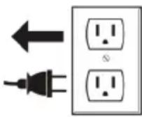
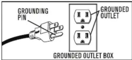
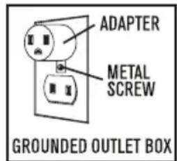
This appliance is for use on a nominal 120-volt circuit, and has a grounded plug that looks like the plug illustrated in sketch A. A temporary adaptor that looks like the adaptor illustrated in sketches B and C may be used to connect this plug to a 2-pole receptacle as shown in sketch B if a properly grounded outlet is not available. The temporary adaptor should be used only until a properly grounded outlet (sketch A) can be installed by a qualified electrician. The green colored rigid ear, lug or the like extending from the adaptor must be connected to a permanent ground such as a properly grounded outlet box cover. Whenever the adaptor is used, it must be held in place by a metal screw.
IN CANADA, THE USE OF A TEMPORARY ADAPTOR IS NOT PERMITTED BY THE CANADIAN ELECTRICAL CODE. Make sure that the appliance is connected to an outlet having the same configuration as the plug. No adaptor should be used with this appliance.
GROUNDING METHODS
text_image
GROUNDING PIN GROUNDED OUTLET GROUNDED OUTLET BOXSKETCH A SKETCH B SKETCH C
text_image
ADAPTER METAL SCREW GROUNDED OUTLET BOX
text_image
ADAPTER TAB FOR GROUNDING SCREWExTENSION CORDS

When using the appliance at a distance where an extension cord becomes necessary, a 3-conductor grounding cord of adequate size must be used for safety, and to prevent loss of power and overheating. Use Table A to determine A.W.G. wire size required. To determine ampere rating of your vacuum, refer to nameplate located on motor housing. Before using appliance, inspect power cord for loose or exposed wires and damaged insulation. Make any needed repairs or replacements before using your appliance. Use only three-wire outdoor extension cords which have three prong grounding-type plugs and three-pole receptacles which accept the extension cord's plug. When vacuuming liquids, be sure the extension cord connection does not come in contact with the liquid.
NOTE: STATIC SHOCKS ARE COMMON IN DRY AREAS OR WHEN THE RELATIVE HUMIDITY OF THE AIR IS LOW. THIS IS ONLY TEMPORARY AND DOES NOT AFFECT THE USE OF THE APPLIANCE. TO REDUCE THE FREQUENCY OF STATIC SHOCKS IN YOUR HOME, THE BEST REMEDY IS TO ADD MOISTURE TO THE AIR WITH A CONSOLE OR INSTALLED HUMIDIFIER.
TABLE A
| Volts | Total length of cord in feet | |||
| 120V | 25 50 100 | 150 | ||
| Ampere Rating More Not More Than Than | AWG | |||
| 0 - 6 | 18 | 16 | 16 | 14 |
| 6 - 10 | 18 | 16 | 14 | 12 |
| 10 - 12 | 16 | 16 | 14 | 12 |
| 12 - 16 | 14 | 12 | Not recommended | |
UNPACKING
Remove vacuum cleaner and all accessories from the carton. Important: Open tank cover by pushing latches or clamps outward with thumbs and remove any accessories that may have been shipped in the tank.
ASSEMBLY
CASTER SYSTEM
Follow the instructions for the caster system that came with your vacuum.
PLASTIC TANK WITH CASTER FEET

You will find four caster feet, four casters and four screws with your vacuum. Assemble as follows:
- With cord disconnected from receptacle and tank cover removed, turn tank upside down so that bottom is facing up.
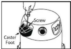
- With front of tank facing you, take caster feet marked with the
letter A and place in slots on left front and right rear of tank also marked with the letter A. Secure with screws provided.
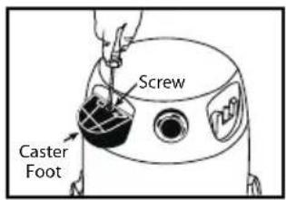
text_image
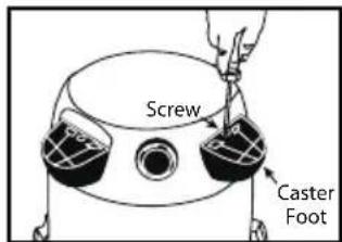
Screw Caster Foot- Take caster feet marked with the letter B and place in slots on right front and left rear of tank also marked with the letter B. Secure with screws provided.
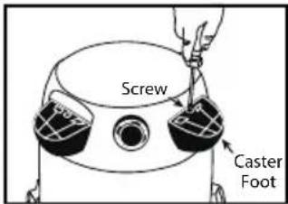
text_image
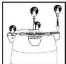
Screw Caster Foot- If flat washers are included in hardware package place flat washer over stem of caster before installing casters into feet. NOTE: Flat washers are not required with all units.
- Insert casters into feet by placing stem of caster into holes provided. Apply pressure and twisting motion until casters snap into place. Return tank to upright position.
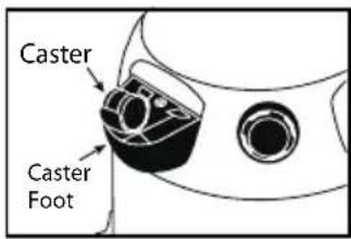
text_image
Caster Caster FootPLASTIC TANK WITH REAR CASTER BASKET

You will find four casters, two caster feet, one basket and four screws with your wet/dry vacuum. If your caster basket looks like the one shown to the right, assemble as follows.
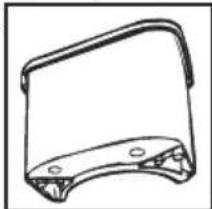
natural_image
Technical line drawing of a mechanical bracket or bracket (no text or symbols)- With cord disconnected from receptacle and tank cover removed, turn tank upside down so that the bottom is facing up.
- Insert two caster feet into adjacent slots at front of tank. Secure with screws provided.
- Take basket and place into remaining slots at back of tank. Secure with screws provided.
natural_image
Simple line drawing of a mechanical component with two parts and a dashed line indicating a reference or alignment (no text or symbols)- Install casters into basket and feet by inserting the caster stems into the holes provided. Apply pressure and twisting motion until casters snap into place.
ASSEMBLY (CONT'D.)
If your caster basket looks like the one shown to the right, assemble as follows.
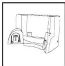
natural_image
Line drawing of a vehicle chassis with wheels and a door (no text or symbols)-
With cord disconnected from receptacle and tank cover removed, turn tank upside down so that the bottom is facing up.
-
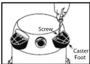
Take basket and place into slots (on rear of tank opposite of drain). Secure with screws provided.
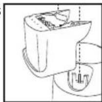
natural_image
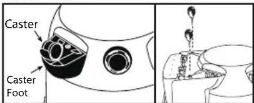
Line drawing of a mechanical device with internal components and a dashed line indicating a reference point (no text or symbols present)- With tank drain facing you, take caster foot marked with the letter A and place in slot on left side of tank also marked with the letter A. Secure with screw provided.
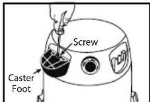
text_image
Screw Caster Foot- Take caster foot marked with the letter B and place in slot on right side of tank also marked with the letter B. Secure with screw provided.
text_image
Screw Caster Foot-
If flat washers are included in hardware package place flat washer over stem of caster before installing casters into feet or basket. NOTE: Flat washers are not required with all units.
-
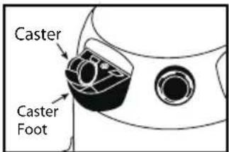
Install casters into caster feet and basket by inserting the caster stems into the holes provided. Apply pressure and twisting motion until caster snap into place.
text_image
Caster Caster FootPLASTIC TANK WITH REAR CASTER DOLLY
You will find four casters, two caster feet, one dolly and four screws with your wet/dry vacuum.

Some units come with an accessory basket. This is not standard on all models.
-
With cord disconnected from receptacle and tank cover removed, turn tank upside down so that the bottom is facing up.
-
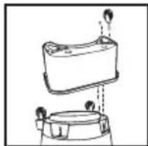
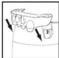
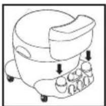
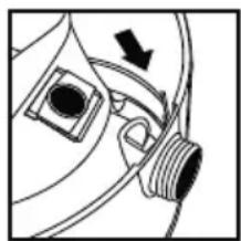
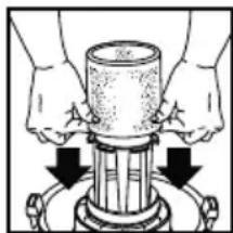
Take rear caster dolly and place into slots (on rear of tank, opposite of drain) and secure with screws provided.
natural_image
Diagram of dental implant components with arrows indicating direction (no text or labels)-
If flat washers are included in hardware package place flat washer over stem of caster before installing casters into feet and dolly. NOTE: Flat washers are not required with all units.
-
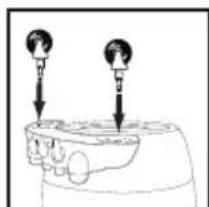
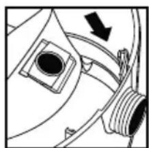
Insert casters into bottom of rear caster dolly by placing stem of caster into holes provided. Apply pressure and twisting motion until casters snap into place.
natural_image
Diagram of a mechanical component with two circular features and downward arrows indicating force or movement (no text or symbols)ASSEMBLY (CONT'D.)
- With tank drain facing you, take caster foot marked with the letter A and place in slot on left side of tank also marked with the letter A and secure with screw provided.
text_image
Screw Caster Foot- Take caster foot marked with the letter B and place in slot on right side of tank also marked with the letter B and secure with screw provided.
text_image
Screw Caster Foot- Insert casters into feet by placing stem of caster into holes provided. Apply pressure and twisting motion until casters snap into place.
natural_image
Simple line drawing of a person standing at a table with three chairs and a bowl, no text or symbols present.-
Return tank to upright position.
-
If an accessory basket came with your unit, place basket with curved surface against tank on rear caster dolly assembly. Push downward until basket snaps onto dolly. The basket is not included with all models.
natural_image
Line drawing of a medical or laboratory device with no visible text, numbers, or symbolsPLASTIC TANK WITH REAR WHEEL BASKET

You will find two casters, two caster feet, two rear wheels, one axle, one basket and four screws with your vacuum.
Assemble as follows:
-
With cord disconnected from receptacle and tank cover removed, turn tank upside down so that bottom is facing up.
-
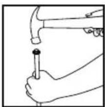
Stand axle upright on hard surface and hammer on one cap nut.
-
Place one wheel on axle and slide down to cap nut. Be sure flat side of wheel hub is facing outward.
-
Slide axle through holes provided in basket.
natural_image
Line drawing of a hand using a hammer to press a screwdriver (no text or symbols present)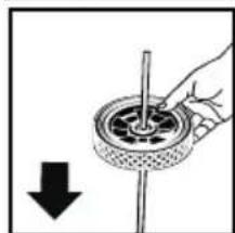
natural_image
Hand holding a circular mechanical component with a pointer, showing a downward arrow (no text or symbols)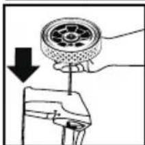
natural_image
Diagram showing a hand holding a wheel with a downward arrow, next to a mechanical component (no text or symbols)ASSEMBLY (CONT'D.)
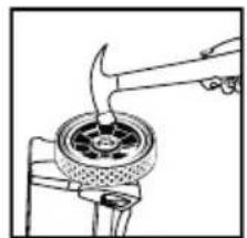
- Slide remaining wheel onto axle. Make sure wheels are positioned correctly. Hammer on second cap nut.
- With front of tank facing you, take basket assembly and place into slots on back of tank. Secure with screws provided.
- Take caster foot marked with the letter A and place in slot on left front of tank also marked with letter A. Secure with screw provided.
- Take caster foot marked with the letter B and place in slot on right front of tank also marked with the letter B. Secure with screw provided.
natural_image
Line drawing of a hand using a tool to stir or burn on a hot pot (no text or symbols)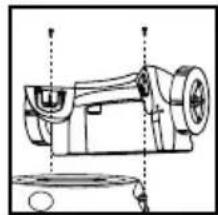
natural_image
Technical line drawing of a mechanical device with no visible text or symbols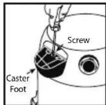
text_image
Screw Caster Foot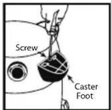
text_image
Screw Caster Foot- If flat washers are included in hardware package place flat washer over stem of caster before installing casters into feet. NOTE: Flat washers are not required with all units.
- Insert casters into feet by placing stem of caster into holes provided. Apply pressure and twisting motion until casters snap into place. Return tank to upright position.
text_image
Caster Caster FootCARRIAGE HANDLE

If your vacuum comes with a carriage handle, assemble as follows:
- Stand tank in the upright position. Spread ends of carriage handle (to prevent damage to tank) while placing them under the side tank handles.
- Align holes in carriage handle with holes in tank. Fasten tightly with screws, washers and nuts provided. The rubber side of the washers must be placed against the inside wall of the tank to prevent leakage or loss of performance.
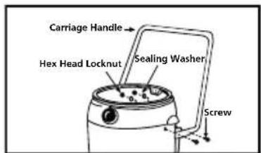
text_image
Carriage Handle Hex Head Locknut Sealing Washer ScrewTOOL HOLDER
(Not standard with all models)
If your unit came with a tool holder, assemble as follows:
- Set tank cover onto the tank. Position with back of tank cover facing you.
- Press tabs of tool holder into the slots on mounting lugs, located on back of tank cover.
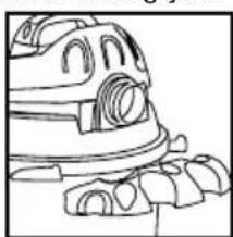
natural_image
Line drawing of a car's front wheel and rear wheels (no text or symbols)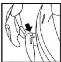
natural_image
Anatomical line drawing of a hand and wrist with a black arrow pointing to a specific area (no text or labels present)ASSEMBLY (CONT'D.)
- Press down until tabs snap into place. Remove tank cover from tank and refer to the set up and operation section.
natural_image
Line drawing of a car with visible engine and roof components (no text or symbols)SET UP AND OPERATION

DANGER
— This equipment incorporates parts such as switches, motors or the arcs or sparks that can cause an explosion. Do not pick up flammable, rials. Do not use around explosive liquids or vapors, as electrical devices which can cause a fire or explosion - do not use at filling stations or ed or dispensed.
- Refer to the filter installation and maintenance section to make sure the correct filters are installed for your cleaning operation.
- Replace tank cover. Make sure each latch or clamp is secured over the raised area of the tank cover. Failure to properly secure the latches could cause the tank cover to release from the tank.
- Insert machine hise end with locking nut into inlet located in the front of the tank. Turn locking nut to tighten. Do not over-tighten.
- Attach the desired cleaning accessory onto the accessory end of the hose. NOTE: Many more useful tools are available at your local dealer or the Shop-Vac® website.
- Plug the cord into the wall outlet. Your cleaner is ready for use.
$$ I = O N, O = O F F $$
natural_image
Pure mechanical diagram showing a pipe fitting with threaded ends and a curved pipe fitting (no text or symbols)ACCESSORIES, HOSES AND WANDS
All Shop-Vac ^® vacuums covered in this manual come with accessories to cover wet and dry cleanup jobs. Not all vacs include all accessories shown.
Nozzles and Accessories
text_image
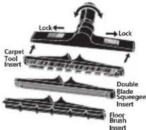
Lock Lock Carpet Tool Insert Double Blade Squeegee Insert Floor Brush Insert14" (35.56cm) ABS Plastic Master Nozzle
Inserts lock into place by
sliding red buttons. Elbow swivels.

text_image
Carpet Tool Insert Squeegee InsertDeluxe 12" (30.48cm) Nozzle
Inserts snap-in and out.
Elbow swivels.
text_image
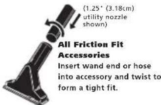
(1.25° (3.18cm) utility nozzle shown) All Friction Fit Accessories Insert wand end or hose into accessory and twist to form a tight fit.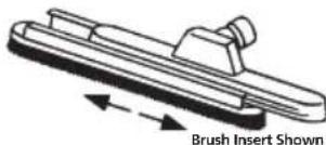
natural_image
Diagram of a brush insert with labeled arrow and text (no other symbols or text)14" (35.56cm) Metal Master Nozzle
Inserts lock into place by sliding insert onto nozzle.

Dual Surface Selector Nozzle
Levers control brush position for various types of cleaning.
Hoses
natural_image
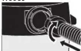
Mechanical assembly diagram showing a threaded component with rotational arrows indicating motion (no text or symbols)All Friction Fit Hoses Insert machine hose end into tank and twist to form a tight fit.
natural_image
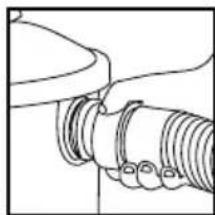
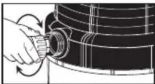
Illustration of a hand adjusting a cylindrical pipe into a black cylindrical container (no text or symbols visible)Posi-Lock Hoses
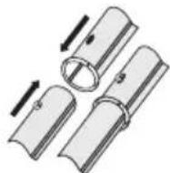
Insert hose collar onto threaded tank inlet and tighten. Do not over-tighten.
Wands
All Friction Fit Wands
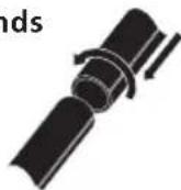
Insert wand ends together and twist to form a tight fit.
Positive Locking Wands
Insert wand ends together until metal push button locks.
natural_image
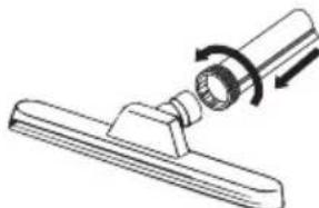
Technical line drawing of a mechanical component with a rotating knob (no text or symbols)Locking Nut Wand End
Insert wand end over nozzle and tighten nut.
FILTER INSTALLATION AND MAINTENANCE
FILTRATION SYSTEM
There are a variety of filters available for your vacuum. There are cage filters that install onto the underside of the tank cover and tank filters that install into the tank. The filters are grouped into three filtration categories. General filtration is used for large debris; such as, wood chips, nails and gravel. Medium filtration is used for medium debris; such as, dirt, sand and sawdust. Fine filtration is used for fine debris; such as drywall dust, cold ash and cement dust. It is important to have the correct filters installed for your cleaning operation to protect your vacuum motor. THE MOST EFFICIENT FILTRATION FOR YOUR VACUUM IS A FINE FILTRATION CAGE FILTER WITH A FINE FILTRATION TANK FILTER.
NOTE: When using the vacuum to pick up very fine dust. It will be necessary to empty the tank and clean the cage filter at more frequent intervals to maintain maximum pick up power or add a disposable filter bag.
NOTE: Never use the vacuum for dry pick up without a dry use filter installed. Using the vacuum without a filter will cause dust to discharge from the blower port and cause damage to the motor.
WARNING — ALWAYS DISCONNECT THE PLUG FROM THE WALL OUTLET BEFORE REMOVING THE TANK COVER.
Follow the instructions for the filter that came with your vacuum. Some filters mentioned do not come standard with all vacuums. Additional filters are available at your local dealer or the Shop-Vac® website.
CARTRIDGE FILTER
The cartridge filter can be used for dry pick up and small quantities of wet pick up. Installation is the same for both. When picking up fine dust or powders a high efficiency filter bag must be used with the cartridge filter.
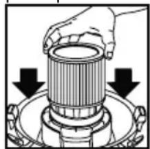
- If a foam sleeve is installed on the lid cage, remove it by sliding it off the lid cage. NOTE: If the cartridge filter has been used for wet pick up, it must be cleaned and dried before using it for dry pick up.
- With the tank cover in an upside down position, slide the cartridge down over the lid cage, pushing until the filter seals against the cover.
natural_image
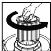
Diagram of a hand holding a cylindrical component with two downward arrows indicating direction (no text or symbols present)- Place the filter retainer into the top of the cartridge filter. Hold the tank cover with one hand, turn the handle on the filter retainer clockwise to lock the filter into place.

natural_image
Illustration of a hand using a tool to press or install a cylindrical component, no text or symbols present- To remove the filter for cleaning, hold the tank cover and turn the filter retainer counter-clockwise to loosen and remove.
natural_image
Diagram of a hand turning a rotating cylindrical component with a curved arrow indicating rotation (no text or symbols)- Slide the cartridge filter off the lid cage.
- For standard cartridge filters and Ultra-Web® cartridge filters, clean the filter by shaking or gently brushing off excess dirt. Extremely dirty filters may be cleaned with water by rinsing from the inside of the filter. Dry completely (approximately 24 hours).
For CleanStream ^® Abrasive Resistant cartridge filter, tap end cap against hard surface to loosen debris. Additional debris can be removed by rinsing outside surface of the filter with running water. Avoid dampening inside of filter. Completely air dry after washing. IMPORTANT: DO NOT BRUSH. DO NOT clean filter with abrasive materials or scrub between pleats. This will permanently damage the filters ability to stop dust.
- Check the filter for tears or small holes. If none are found, reinstall the filter. To prevent damage to your vacuum, do not use a filter with a hole or tear.
FILTER INSTALLATION AND MAINTENANCE(CONT'D.)
NOTICE — This filter is made of high quality paper designed to stop small particles of dust. The filter can be used for wet or dry pick up. A dry filter is necessary to pick up dry material. If you use your vac to pick up dust when the filter is wet, the filter will clog quickly and be very difficult to clean. The filter may become saturated when picking up large quantities of liquid causing misting to appear in the exhaust air. At this time, you should dry or change the filter to eliminate this occurrence. Please handle the filter carefully when removing it for cleaning or when installing it. Check the filter for tears or small holes. Even a small hole can cause dust to be exhausted. Do not use a filter with holes or tears. Replace it immediately.
WARNING — KEEP FILTERS CLEAN. EFFICIENCY OF THE VACUUM IS LARGELY DEPENDENT ON THE FILTER. A CLOGGED FILTER CAN CAUSE OVERHEATING AND POSSIBLY DAMAGE THE CLEANER. CHECK THE FILTER PERIODICALLY AND REPLACE AS REQUIRED.
DISPOSABLE FILTER BAG
Use the disposable filter bag in conjunction with the cartridge filter for easy disposal of the debris. The bag is not required for normal dry pick up. When picking up fine dust or powders a high efficiency filter bag must be used. NOTE: For dry use only.
Follow the instructions that pertain to your vacuum.
TANK WITH STATIONARY INLET DEFLECTOR:
-
Make sure the cord is disconnected from the receptacle, tank cover is removed and the hose is disconnected from tank inlet.
-
Grasp the cardboard collar firmly and slide rubber guard onto inlet fitting as far as possible.
natural_image
Pure mechanical diagram showing a pipe fitting with a valve and circular component, no text or symbols present-
When secured in place, expand the filter bag and position around the inside of the tank. TANK WITH REMOVABLE INLET DEFLECTOR:
-
Make sure the cord is disconnected from the receptacle, tank cover is removed and the hose is disconnected from tank inlet.
-
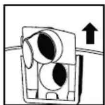
Remove inlet deflector from deflector guide. NOTE: Hose must be removed before inlet deflector can be taken out.
natural_image
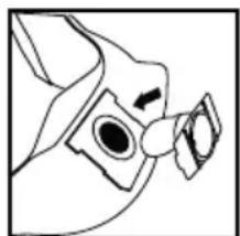
Simple line drawing of a mechanical device with an upward arrow, no text or symbols present- With the opening of the inlet deflector facing the left or right side of the filter bag, slide filter bag collar over deflector matching notches of bag collar to tabs on inlet deflector. Bag will only fit properly one way.
natural_image
Simple line drawing of a bird's head and neck (no text or symbols)- Slide deflector with filter bag attached into deflector guide.
natural_image
Pure mechanical diagram showing a component with a circular opening and threaded end, no text or symbols present- Reinsert hose into inlet and tighten locking-nut. When secured in place expand bag and position around inside of tank.
FILTER INSTALLATION AND MAINTENANCE(CONT'D.)
- NOTE: When removing filter bag from tank, remove inlet deflector from filter bag collar and reinstall into deflector guide. Inlet deflector should always be in place for any type of cleaning.

WARNING — FOR FINE DUST AND POWDERS.
When vacuuming fine dust, or powders of any kind (plaster, drywall dust, cold ashes, concrete dust, etc.) a high efficiency drywall filter bag must be used. When vacuuming normal household dust and debris, standard household disposable filter bags may be used.
- Your vacuum can be used for wet pick up. Remove ALL dirt and debris found in the tank. Remove all dry use filters, including the filter bag, from the vacuum.
- A clean cartridge filter may be used to pick up small quantities of liquid. To use the cartridge filter; follow the instructions under dry pick up.
- For vacuuming large quantities of liquid use a foam sleeve. If a foam sleeve did not come standard with your unit, one may be purchased at your local dealer, the Shop-Vac ^® website or by contacting Shop-Vac ^® customer service. To use the foam sleeve; follow the instructions in this section.
- Misting in the exhaust air or dripping of liquid around the tank cover may occur if the filter becomes saturated during wet pick up. If this occurs, remove the filter and allow to dry, or replace with another dry filter.
- Turn the unit off immediately upon completing a wet pick up job or when tank is full and ready to be emptied. When the tank is full, suction will drastically reduce. Refer to the automatic suction shut off section for more information. Raise the hose to drain any excess liquid into the tank. Follow the instructions in the emptying liquid waste section.
- Before storing the vacuum cleaner or using for dry pick up, clean and dry the interior of the tank and the underside of the tank cover. Clean and allow the filters to dry completely.
- Wet pick up accessories should be washed periodically; especially after picking up wet, sticky kitchen accidents. This can be accomplished with a warm solution of soap and water.
natural_image
Illustration of hands operating a cylindrical mechanical device with arrows indicating motion (no text or symbols)FOAM SLEEVE
- With the tank cover in an upside down position, slide the foam sleeve down over the lid cage, pulling until foam sleeve completely covers the lid cage.
- To clean the foam sleeve, side it up and off the lid cage. Shake excess debris off of the foam sleeve with a rapid up and down movement.
- Hold foam sleeve under running water for a couple minutes, rinsing from the inside of the filter. A water wash is not always required, depending on the condition of the filter.
- Check the filter for tears. If any are found, replace with a new filter.
natural_image
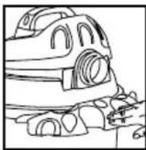
Illustration of a tank with a circular head and a black arrow pointing to the nose (no text or symbols)BLOWER FEATURE
Your vacuum can be used as a powerful blower. To use the blower feature, clear the hose of any debris or obstructions.
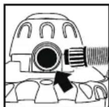
For vacuums with a blower port cover (not standard on all models), unscrew blower port cover located on the back of tank cover. The blower port cover is equipped with a retaining strap to prevent loss of the cover. NOTE: For maximum performance when vacuuming, remove the blower port cover.
Insert machine hose end into blower port located on the back of the tank cover.
Twist the hose end slightly to tighten the connection. Caution should be used when using as a blower due to the powerful force of air when using certain attachments.

WARNING — ALWAYS WEAR EYE PROTECTION TO PREVENT ROCKS OR
DEBRIS FROM BEING BLOWN OR RICOCHETING INTO THE EYES OR FACE WHICH CAN RESULT IN SERIOUS INJURY.
EMPTYING LIQUID WASTE FROM THE TANK
To empty liquid waste from the tank, turn the vacuum off and remove the plug from the wall outlet. Follow the instructions that pertain to your vacuum.
WITHOUT TANK DRAIN
Remove the tank cover and deposit the liquid waste in a suitable drain. Use side carry handles for lifting vac when draining tank into drains that are located above floor level. After tank is empty, return the tank cover to its original position.
WITH TANK DRAIN
Remove the drain cap and deposit the liquid waste in a suitable drain. Use side carry handles for lifting vac when draining tank into drains that are located above floor level. After the tank is empty, return the drain cap to its original position.
AUTOMATIC SUCTION SHUT OFF
The vacuum is equipped with an automatic suction shut-off that operates when picking up liquids. As the level of the liquid rises in the tank, an internal float rises until it seats itself against a seal at the intake of the motor, shutting off suction. When this happens, the motor will develop a higher than normal pitch noise and the suction is drastically reduced. If this occurs, turn unit off immediately. Failure to turn unit off after float rises and shuts off suction will result in extensive damage to the motor. To continue use, empty the liquid waste from the tank as outlined in the previous section.
NOTE: IF ACCIDENTALLY TIPPED OVER, THE VACUUM COULD LOSE SUCTION, IF THIS OCCURS, TURN UNIT OFF AND PLACE VAC IN UPRIGHT POSITION. THIS WILL ALLOW THE FLOAT TO RETURN TO ITS NORMAL POSITION AND YOU WILL BE ABLE TO CONTINUE OPERATION.
LUBRICATION
No lubrication is necessary as the motor is equipped with lifetime lubricated bearings.
STORAGE
Before storing your vacuum the tank should be emptied and cleaned. Never allow liquids to sit in the tank for any extended period of time. The vacuum should be stored indoors.
SERVICE
Do not attempt to service your Shop-Vac® wet/dry vacuum cleaner beyond that described in this manual. Refer all other servicing to a qualified service center.
TROUBLESHOOTING
| PROBLEM | POSSIBLE CAUSES | SOLUTION |
| Parts/accessories 1. missing | Packed in tank 1. Check in tank | |
| Vacuum cleaner 1. will not start 2. Defective switch customer service3. Defective motor customer service | No power at receptacle 1. Check for 2. Contact Shop-Vac 3. Contact Shop-Vac 3. Use more efficient filter 4. Clean or replace filter | power®® |
| Dust discharging 1. from exhaust properly2. Filter damaged 2. Replace filter3. Filter clogged or dust is too fine 3. Use more efficient filter4. Filter not functional 4. Clean or replace filter | ||
| Loss of suction2. Filter clogged3. Full tank4. Hole in hose | Loose hose connection 1. Tighten hose connection2. Clean or replace filter3. Empty tank4. Replace hose | |
| Static shockor installed humidifier).2. Relative humidity of air is low and does not affect the use of the vacuum cleaner. | Dry environment2. This situation is temporary | |
WARNING — IF ANY OF THE MOTOR HOUSING PARTS SHOULD BECOME DETACHED OR BROKEN, EXPOSING THE MOTOR OR ANY OTHER ELECTRICAL COMPONENTS, OPERATION SHOULD BE DISCONTINUED IMMEDIATELY TO AVOID PERSONAL INJURY OR FURTHER DAMAGE TO THE VACUUM. REPAIRS SHOULD BE MADE BEFORE REUSING THE VACUUM.
ONE YEAR INDUSTRIAL/COMMERCIAL WARRANTY
One year limited warranty
Shop-Vac® Corporation warrants the vacuum cleaner contained in this package for one year from the date of purchase to correct by repair or parts replacement without charge any product defect due to faulty material or workmanship. Should this product be used for rental service, a 90 day limited warranty will apply. THIS WARRANTY DOES NOT COVER ACCESSORIES. Shop-Vac® assumes no responsibility for damage or faulty performance caused by misuse or careless handling, or where repairs or modifications have been made or attempted by others. Proof of purchase date is required. This warranty gives you specific legal rights, and you may also have other rights which vary from state to state or province to province.
Customers in the United States: for product service contact Shop-Vac® Corporation Customer Service, at (570) 326-3557 or go to www.shopvac.com/support. Visit www.shopvac.com for your vacuum's parts list schematic.
Customers in Canada: for product service return the complete unit, (transportation prepaid), to the Authorized Shop-Vac® Service Centre nearest you. Visit www.shopvac.ca for a complete list of authorized service centres in your area.
Customers in Mexico: for product service see paperwork that came with your unit.
SHOP-VAC CORPORATION
2323 Reach Road, P.O. Box 3307
Williamsport, PA 17701-0307
(570) 326-3557
www.shopvac.com
SHOP-VAC CANADA
1770 Appleby Line
Burlington, Ontario L7L 5P8
(905) 335-9730
www.shopvac.ca
Shop Vac-México, S.A. de C.V.
Patents Issued and Pending.
© 2014 Shop-Vac Corporation. All Rights Reserved.
MANUEL D'UTILISATION
Lubrification ....14
Rangement....14
Entretien....14
Dépannage 15
natural_image
Simple line drawing of a hammer (no text or symbols)natural_image
Technical line drawing of a mechanical bracket or bracket (no text or symbols)natural_image
Simple line drawing of a mechanical component with two parts stacked vertically (no text or symbols)natural_image
Line drawing of a vehicle chassis with a door and seat (no text or symbols)natural_image
Line drawing of a mechanical device with internal components and a dashed line indicating a reference point (no text or symbols present)natural_image
Diagram of dental implant components with arrows indicating direction (no text or labels)natural_image
Diagram of a hand holding a small object with two circular objects above it, no text or symbols present.natural_image
Simple line drawing of a person standing at a table with three hanging objects above their heads (no text or symbols)
natural_image
Line drawing of a medical or laboratory device with no visible text, numbers, or symbolsASSEMBLAGE (SUITE)
RÉSERVOIR DE PLASTIQUE AVEC PANIER ARRIÈRE

text_image
Diagram illustrating the step-by-step procedure for using a lathe machine to adjust a lathe component, with labeled parts including 'Vis' and 'Patte à roulette'.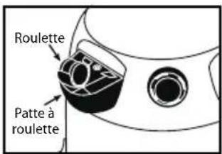
natural_image
Line drawing of a mechanical component with no visible text or symbols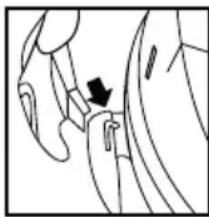
natural_image
Anatomical line drawing of a human hand and wrist with a black arrow pointing to a specific area (no text or labels present)natural_image
Line drawing of a car with visible engine and wheels (no text or symbols)CONFIGURATION ET LE FONCTIONNEMENT

natural_image
Pure mechanical diagram showing a pipe fitting with no text or symbolsI = EN MARCHE, O = À L'ARRÊT
CONFIGURATION ET LE FONCTIONNEMENT (SUITE)
ACCESSOIRES, TUYAUX SOUPLES ET RALLONGES
natural_image
Technical line drawing of a mechanical component with bidirectional arrows indicating measurement (no text or symbols)natural_image
Diagram of a mechanical component with a threaded rod and circular features, showing rotational motion (no text or symbols)natural_image
Hand holding a cylindrical component with rotating arrows, no visible text or symbolsnatural_image
Technical line drawing of a mechanical component with a rotating knob (no text or symbols)natural_image
Diagram of a hand holding a cylindrical component with two downward arrows indicating direction (no text or symbols present)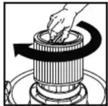
natural_image
Illustration of a hand using a tool to press or adjust a cylindrical component on a stovetop (no text or symbols visible)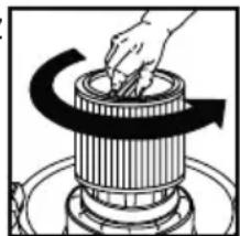
natural_image
Illustration of a hand turning a rotating mechanical component with a curved arrow indicating rotation (no text or symbols)natural_image
Pure mechanical diagram showing a pipe fitting with a valve and arrow indicating direction (no text or symbols)natural_image
Simple line drawing of a mechanical component with an upward arrow, no text or symbols present.natural_image
Simple line drawing of a bird's head and neck with no text or symbolsnatural_image
Pure mechanical diagram showing a valve or fitting with a circular component and directional arrow (no text or symbols)natural_image
Illustration of hands operating a cylindrical mechanical component with arrows indicating downward motion (no text or symbols)CARACTÉRISTIQUE DE LA SOUFFLEUSE
natural_image
Illustration of a tank with a circular head and arrow pointing to the nose (no text or symbols)2323 Reach Road, P.O. Box 3307
Williamsport, PA 17701-0307
(570) 326-3557
www.shopvac.com
SHOP-VAC CANADA
1770 Appleby Line
Burlington, Ontario L7L 5P8
(905) 335-9730
www.shopvac.ca
Shop Vac-México, S.A. de C.V.
natural_image
Simple line drawing of a hammer (no text or symbols)natural_image
Simple line drawing of a mechanical bracket or bracket (no text or symbols)natural_image
Diagram of a mechanical component with two views, showing top and side views (no text or symbols)natural_image
Line drawing of a mechanical device with a curved base and internal components (no text or symbols)natural_image
Technical line drawing of a mechanical device with no visible text or symbolsnatural_image
Diagram of a dental implant or dental implant component with arrows indicating direction (no text or labels)natural_image
Simple line drawing of a hand holding a bowl with two arrows pointing downward (no text or symbols)natural_image
Simple line drawing of a laboratory setup with three cups and a tray (no text or symbols)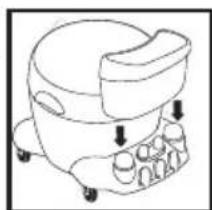
natural_image
Line drawing of a medical or laboratory device with no visible text, numbers, or symbolsMONTAJE (CONT.)
DEPÓSITO PLÁSTICO CON CESTA TRASERA

natural_image
Line drawing of hands using a hammer to apply a screwdriver (no text or symbols present)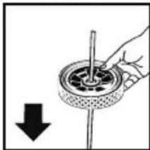
natural_image
Hand holding a circular mechanical component with a pointer, accompanied by a downward arrow (no text or symbols)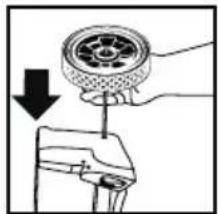
natural_image
Diagram showing a hand holding a circular component with a downward arrow, no text or symbols present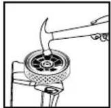
natural_image
Illustration of a hand using a tool to lift a circular mechanical component (no text or symbols visible)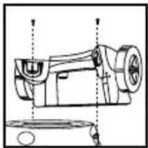
natural_image
Technical line drawing of a sewing machine (no text or symbols)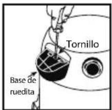
text_image
Tornillo Base de ruedita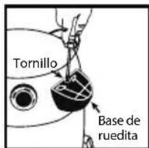
text_image
Tornillo Base de ruedita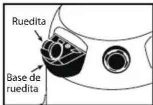
text_image
Ruedita Base de rueditaMONTAJE (CONT.)
MANIJA DE TRANSPORTE

natural_image
Line drawing of a mechanical component with no visible text or symbols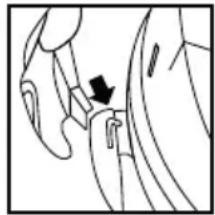
natural_image
Line drawing of a hand holding a small object with an arrow pointing to it (no text or symbols present)natural_image
Line drawing of a car with wheels and roof, no text or symbols presentnatural_image
Pure mechanical diagram showing a pipe fitting with no text or symbolsnatural_image
Mechanical diagram showing a threaded component with rotational arrows indicating motion (no text or symbols)natural_image
Hand holding a cylindrical component with curved arrows indicating rotation (no text or symbols)natural_image
Technical line drawing of a mechanical component with a rotating knob (no text or symbols)natural_image
Diagram of a hand pressing down on a cylindrical component with arrows indicating downward motion (no text or symbols)natural_image
Illustration of a hand using a coiled spring to press down a cylindrical component (no text or symbols visible)natural_image
Illustration of a hand turning a rotating mechanical component with a curved arrow indicating rotation (no text or symbols)natural_image
Pure mechanical diagram showing a pipe fitting with a valve and circular component, no text or symbols presentnatural_image
Simple line drawing of a mechanical device with an upward arrow, no text or symbols present.natural_image
Simple line drawing of a mechanical component with no text or symbolsnatural_image
Pure mechanical diagram showing a component with a circular opening and threaded end, no text or symbols presentMANGA DE HULE-ESPUMA
natural_image
Illustration of hands operating a cylindrical mechanical device with arrows indicating motion (no text or symbols)natural_image
Diagram of a mechanical component with a circular feature and a threaded rod, no visible text or symbols2323 Reach Road, P.O. Box 3307
Williamsport, PA 17701-0307
(570) 326-3557
www.shopvac.com
SHOP-VAC CANADA
1770 Appleby Line
Burlington, Ontario L7L 5P8
(905) 335-9730
www.shopvac.ca