
DXIG3600E - Generator DEWALT - Free user manual and instructions
Find the device manual for free DXIG3600E DEWALT in PDF.

| Product type | Generator |
| Brand | DEWALT |
| Model | DXIG3600E |
| Rated voltage | 120/240 V |
| Frequency | 60 Hz |
| Maximum power | 3600 W |
| Continuous power | 3000 W |
| Engine type | 4-stroke, gasoline |
| Tank capacity | 5 gallons (approx. 19 L) |
| Noise level | 70 dB (estimated) |
| Dimensions (L x W x H) | 600 x 400 x 400 mm |
| Weight | 45 kg |
| Outlets | 2 outlets 120 V, 1 outlet 240 V |
| Safety | Overload protection, grounding |
| Maintenance | Check oil, clean air filter, drain tank |
| Warranty | 1 year |
| Included accessories | User manual, spark plugs, drain key |
Frequently Asked Questions - DXIG3600E DEWALT
User questions about DXIG3600E DEWALT
0 question about this device. Answer the ones you know or ask your own.
Ask a new question about this device
Download the instructions for your Generator in PDF format for free! Find your manual DXIG3600E - DEWALT and take your electronic device back in hand. On this page are published all the documents necessary for the use of your device. DXIG3600E by DEWALT.
USER MANUAL DXIG3600E DEWALT
DW678,680/328494-01 1/13/00 11:24 AM Page 2
DEWALT Industrial Tool Co., 701 Joppa Road, Baltimore, MD 21286
DW677, DW678 Copyright © 1997
Printed in Italy (OCT97-1)
Form No. 328494
DW678, 680/328494-01 1/13/00 11:24 AM Page 3
INSTRUCTION MANUAL GUIDE D'UTILISATION MANUAL DE INSTRUCCIONES
General Safety Instructions
⚠ WARNING! Read and understand all instructions. Failure to follow all instructions listed below, may result in electric shock, fire and/or serious personal injury.
SAVE THESE INSTRUCTIONS
WORK AREA
- Keep your work area clean and well lit. Cluttered benches and dark areas invite accidents.
- Do not operate power tools in explosive atmospheres, such as in the presence of flammable liquids, gases, or dust. Power tools create sparks which may ignite the dust or fumes.
- Keep bystanders, children, and visitors away while operating a power tool. Distractions can cause you to lose control.
ELECTRICAL SAFETY
- Grounded tools must be plugged into an outlet properly installed and grounded in accordance with all codes and ordinances. Never remove the grounding prong or modify the plug in any way. Do not use any adaptor plugs. Check with a qualified electrician if you are in doubt as to whether the outlet is properly grounded. If the tools should electrically malfunction or break down, grounding provides a low resistance path to carry electricity away from the user. Applicable only to Class I (Grounded) tools.
-
Double insulated tools are equipped with a polarized plug (one blade is wider than the other.) This plug will fit in a polarized outlet only one way. If the plug does not fit fully in the outlet, reverse the plug. If it still does not fit, contact a qualified electrician to install a polarized outlet. Do not change the plug in any way. Double insulation □ eliminates the need for the three wire grounded power cord and grounded power supply system. Applicable only to Class II (Double Insulated) tools.
-
Avoid body contact with grounded surfaces such as pipes, radiators, ranges and refrigerators. There is an increased risk of electric shock if your body is grounded.
- Don't expose power tools to rain or wet conditions. Water entering a power tool will increase the risk of electric shock.
- Do not abuse the cord. Never use the cord to carry the tools or pull the plug from an outlet. Keep cord away from heat, oil, sharp edges or moving parts. Replace damaged cords immediately. Damaged cords increase the risk of electric shock.
- When operating a power tool outside, use an outdoor extension cord marked "W-A" or "W." These cords are rated for outdoor use and reduce the risk of electric shock. Recommended Minimum Wire Size for Extension Cords
Total Length of Cord
25 ft. 50 ft. 75 ft. 100 ft. 125 ft. 150 ft. 175 ft.
7.6 m 15.2 m 22.9 m 30.5 m 38.1 m 45.7 m 53.3 m
Wire Size
18 AWG 18 AWG 16 AWG 16 AWG 14 AWG 14 AWG 12 AWG
PERSONAL SAFETY
- Stay alert, watch what you are doing and use common sense when operating a power tool. Do not use tool while tired or under the influence of drugs, alcohol, or medication. A moment of inattention while operating power tools may result in serious personal injury,
- Dress properly. Do not wear loose clothing or jewelry. Contain long hair. Keep your hair, clothing, and gloves away from moving parts. Loose clothes, jewelry, or long hair can be caught in moving parts.
- Avoid accidental starting. Be sure switch is off before plugging in. Carrying tools with your finger on the switch or plugging in tools that have the switch on invites accidents.
- Remove adjusting keys or wrenches before turning the tool on.
A wrench or a key that is left attached to a rotating part of the tool may result in personal injury.
- Do not overreach. Keep proper footing and balance at all times. Proper footing and balance enables better control of the tool in unexpected situations.
- Use safety equipment. Always wear eye protection. Dust mask, non-skid safety shoes, hard hat, or hearing protection must be used for appropriate conditions.
TOOL USE AND CARE
- Use clamps or other practical way to secure and support the workpiece to a stable platform. Holding the work by hand or against your body is unstable and may lead to loss of control.
- Do not force tool. Use the correct tool for your application. The correct tool will do the job better and safer at the rate for which it is designed.
- Do not use tool if switch does not turn it on or off. Any tool that cannot be controlled with the switch is dangerous and must be repaired.
- Disconnect the plug from the power source before making any adjustments, changing accessories, or storing the tool. Such preventative safety measures reduce the risk of starting the tool accidentally.
- Store idle tools out of reach of children and other untrained persons. Tools are dangerous in the hands of untrained users.
- Maintain tools with care. Keep cutting tools sharp and clean. Properly maintained tools, with sharp cutting edges are less likely to bind and are easier to control.
- Check for misalignment or binding of moving parts, breakage of parts, and any other condition that may affect the tools operation. If damaged, have the tool serviced before using. Many accidents are caused by poorly maintained tools.
- Use only accessories that are recommended by the manufacturer for your model. Accessories that may be suitable for one tool, may become hazardous when used on another tool.
SERVICE
- Tool service must be performed only by qualified repair personnel. Service or maintenance performed by unqualified personnel could result in a risk of injury.
- When servicing a tool, use only identical replacement parts. Follow instructions in the Maintenance section of this manual. Use of unauthorized parts or failure to follow Maintenance Instructions may create a risk of electric shock or injury.
Additional Safety Instructions for Planers
⚠ WARNING: Use of this tool can generate dust containing chemicals known to cause cancer, birth defects or other reproductive harm. Use appropriate respiratory protection.
- Be sure to read instruction manual thoroughly before using this tool.
- Be sure the voltage agrees with specific data on the nameplate.
- Be sure the switch is in OFF position before connecting tool to power supply.
- Be sure to switch OFF immediately if tool is jammed in work.
- Be sure tool is disconnected from power source when cleaning or making adjustments to the tool.
- Be sure tool is properly held or set for right use before turning switch to ON.
- Be sure to use specified replacement parts only.
- Be sure to maintain tool with care. Follow instructions for lubricating and changing accessories.
- Be sure to store tool in a clean dry place after disconnecting from power source.
- Keep air vents unobstructed for proper motor cooling.
- DO NOT lay tool down on shoe when the blades are exposed. This can chip the blades.
- Keep side discharge chute unobstructed at all times.
English
- Never reach under the tool for any reason unless it is turned off and UNPLUGGED. BLADES ARE EXPOSED AND EXTREMELY SHARP.
- Use this tool for working with wood and wood products only.
- Never operate without securely holding the front handle.
• Always operate planer with two hands. - Planer blades are extremely sharp - Handle with great care.
CAUTION: Some wood contains preservatives such as copper chromium arsenate (CCA) which can be toxic. When sanding, drilling, or cutting these materials extra care should be taken to avoid inhalation and minimize skin contact. - The label on your tool may include the following symbols.
V....volts
A.....amperes
Hz......hertz
W ......watts
min minutes
\~ ......alternating current
=.....direct current
no no load speed
☐ Class II Construction
.../min....revolutions or reciprocation per minute
earthing terminal
⚠️ ......safety alert symbol
SAVE THESE INSTRUCTIONS
Motor
Be sure your power supply agrees with nameplate marking.
120 volts AC only means your tool may be operated only with alternating current and never with direct current.
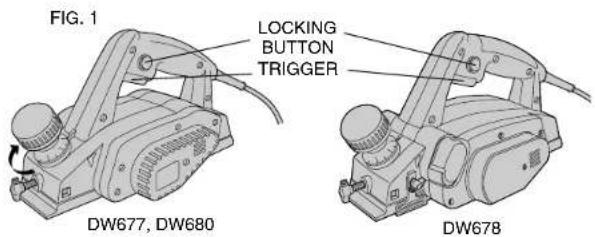
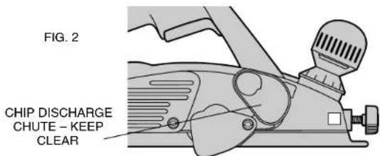
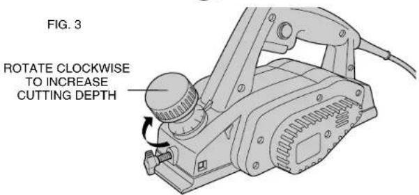
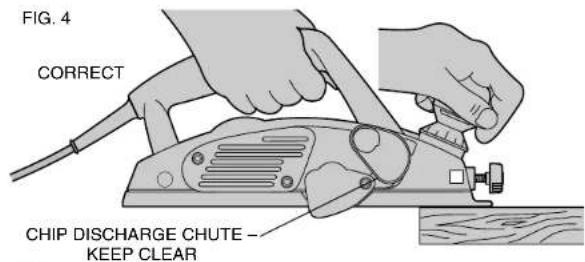
FIG. 5
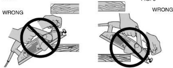
FIG. 7
Voltage decrease of more than 10% will cause loss of power and overheating. All DEWALT tools are factory tested; if this tool does not operate, check the power supply.
Operation
SWITCH
ALWAYS PICK UP YOUR PLANER BEFORE DEPRESSING THE SWITCH. The planer is started by depressing the trigger in the handle. To turn the planer OFF, release the trigger.
To LOCK the tool ON, for continuous use, hold the trigger depressed and push in the locking button shown in Figure 1. Hold the button in while gently releasing the trigger. To turn the tool OFF from a locked-on position, depress and release the trigger once.
ADJUSTING PLANING DEPTH
Turn off and unplug Planer. Planing depth is infinitely variable from 0 to .059" (1.5mm) using the DW677, from 0 to .157" (4.0mm) using the DW678, and 0 to .098" (2.5 mm) using the DW680. This is adjustable by rotating the knob on the top of the planer near the front, as shown in Figure 3. As the knob is rotated clockwise from the "O" position the cutting depth will increase from 0 to as much as .157". Each click of the adjustment knob represents approximately 0.1mm of depth. It is recommended that test cuts be made in scrap wood after each re-adjustment to make sure that the desired amount of wood is being removed by the planer. Several shallow passes will produce a smoother finish than one deep one.
PLANING
Hold the planer as shown in Figure 4 with one hand on the switch handle and the other hand on the front handle. Place the front shoe on the surface to be planed, making certain that the cutting blades are not touching the surface. Push down firmly on the front handle of the planer so that the front shoe is ABSOLUTLEY FLAT on the work surface. Pull the trigger switch and allow the motor to reach full speed before beginning to plane.
English
Move the tool slowly into the work and maintain downward pressure to keep the planer flat. Be particularly careful to keep the tool flat at the beginning and the end of the work surface, see Figures 5 and 6.
PLANING TIP: For a smoother appearance, fasten a piece of scrap wood to the end of the piece you are planing. Don't stop planing until the cutting blades of the planer are past your work piece and into the scrap material.
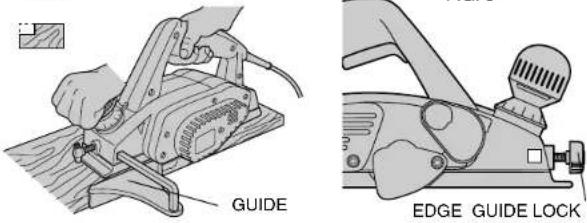
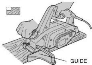
RABBETING
Your planer can make rabbit cuts up to .5" (12mm) using the DW677 and DW680 or 1" (25mm) using the DW678 with the edge guide. To make a rabbit cut, adjust the edge guide (see Figure 8) for the desired width of cut. Make several cuts until the desired depth is reached.
NOTE: It will be necessary to make quite a few cuts for most rabbet applications.
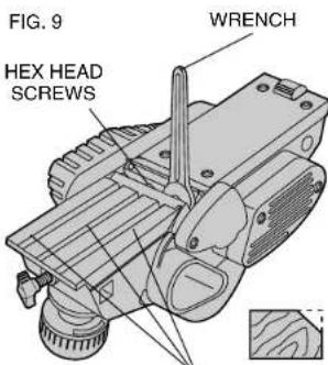
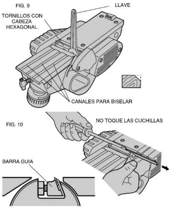
How to Change and Adjust Carbide Blades (DW677, DW678) Fig. 9 - 12
For best results, keep the blades clean and replace when necessary. Replacement blades are available at your local authorized DEWALT service center.
NOTE: Blades are double edged and reversible for extended cutting life.
TO CHANGE BLADES
Turn off and unplug planer. Perform steps 1 through 5 on both blades in blade drum. NOTE: Use only DW6654 replacement blades in your DEWALT planer.
- Loosen the three hex head screws with the wrench provided (Fig. 9).
- Loosen (do not remove) the three screws shown in Figure 9. NOTE: There are two blades in the blade drum. Every operation you perform on one blade, you will also perform on the other.
- With the three screws loose, push the old blade out with a
CHAMFERING GROOVES
FIG. 10
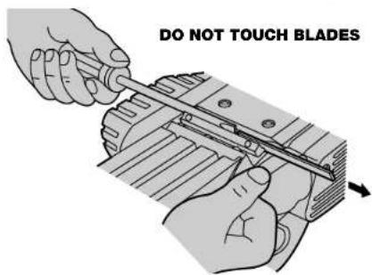
screwdriver (Fig.10). The blades have two cutting edges on them. If this is the first time you are changing blades, you need only to turn the blade around to expose the fresh cutting edge. Otherwise you will have to replace the blades.
- Install the new (or reversed) blade as shown in the close-up view shown in Figure 10. Slide the blade all the way in until the end of it is flush with the end of the blade drum.
- Securely tighten all three screws (for both blades).
NOTE: Be sure that screws are tight.
How to Change Planer Blades (DW680)
- Loosen the three bolts with the allen wrench provided.
NOTE: There are two blades in the blade drum. Any operation or adjustment should be duplicated on both. - Remove the drum cover
- Remove blade:
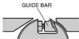
a. Remove a Carbide blade with blade carrier and guide bar b. Remove a High Speed Steel blade by itself.
- Place the blade carrier with the beveled edge facing up and the guide bar with the rounded edge facing down. The holes should match on both pieces. Then screw the guide bar to the blade carrier loosely.
- Place the planer blade face up on the gauge plate with the cutting edge of the blade perfectly flush with gauge plate inside wall.
- Gauge Plate:
a. Place the guide bar on top of the High Speed steel blade so that the holes match.
b. Set the attached blade carrier notches in the Carbide blade on the gauge plate.
7. Push the heel of the guide bar until it grips gauge plate end and tighten the screws.
BLADE CARRIER DW680
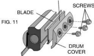
FIG. 12
DW680 SHOWN
FIG. 13
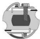
NOTE: The blade must sit flush with the inside wall of the of the gauge plate. The blade carrier notches must sit in the blade groove. The heel of the guide bar must be flush with the back side of the gauge plate. Check this alignment carefully to ensure uniform cutting.
- Put the heel of the guide bar into the groove of the drum.
- Replace the drum cover over the guide bar/blade carrier and screw in the three hex head screws leaving a small space between the drum and the blade carrier.
- Slide the carbide blade between the drum and blade carrier with the flat side of the blade against the drum
- The blade will be positioned by the planer blade groove and notches on the blade carrier.

natural_image
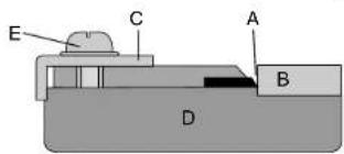
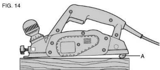
Line drawing of a manual power tool on a wooden base, labeled 'FIG. 14' and marked with point 'A' (no text or symbols on the diagram itself)Setting the Adjustment Plate (Fig. 13)
- Place blade edge (A) touching the inside edge of gauge plate (B).
- Place adjusting plate (C) on blade with the heel flush against the base (D).
- Fit and tighten the two blade holder screws (E).
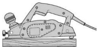
Parking Foot (Fig. 14)
Your planer is equipped with a parking foot (A) that automatically falls down into place when the tool is lifted from the work surface. When planing, the parking foot folds up, out of the way, as the tool is pushed forward. When the parking foot is down, the tool can be left standing on the work surface without the blade touching the work.
⚠ CAUTION: Do not lock the trigger switch on and engage the parking foot. The vibration of the running motor will cause the planer to move, possibly falling from the work piece.
Edge Chamfering
Your planer has 3 precision machined grooves in the front shoe for planing along a corner of the wood (Fig. 9). The width of the grooves are 1.5mm, 2mm, and 2.5mm. It's a good idea to try a piece of scrap wood before doing finish work.

Cleaning & Lubrication
Use only mild soap and damp cloth to clean the tool. Never let any liquid get inside the tool; never immerse any part of the tool into a liquid.
Self-lubricating bearings are used in the tool and periodic relubrication is not required. If you need service or assistance in locating any accessory, please contact:
DEWALT Industrial Tool Company,
P.O. Box 158, 626 Hanover Pike,
Hampstead, MD 21074
or call 1-800-4-DEWALT (1-800-433-9258).
Accessories
Recommended accessories for use with your tool are available at extra cost from your distributor or authorized service center.
⚠️ CAUTION: The use of any non-recommended accessory may be hazardous.
Important
To assure product SAFETY and RELIABILITY, repairs, maintenance and adjustment (including brush inspection and replacement) should be performed by authorized service centers or other qualified service organizations, always using identical replacement parts.
Full Warranty
DEWALT heavy duty industrial tools are warranted for one year from date of purchase. We will repair, without charge, any defects due to faulty materials or workmanship. For warranty repair information, call 1-800-4-DEWALT. This warranty does not apply to accessories or damage caused where repairs have been made or attempted by others. This warranty gives you specific legal rights and you may have other rights which vary in certain states or provinces.
DW678,680/328494-01 1/13/00 11:24 AM Page 7
In addition to the warranty, DEWALT tools are covered by our:
30 DAY NO RISK SATISFACTION GUARANTEE
If you are not completely satisfied with the performance of your DEWALT heavy duty industrial tool, simply return it to the participating seller within 30 days for a full refund. Please return the complete unit, transportation prepaid. Proof of purchase may be required.
See 'Tools-Electric'
- Yellow Pages -
for Service & Sales

7

DW678,680/328494-01 1/13/00 11:24 AM Page 10
natural_image
Technical line drawing of a mechanical device with a knob and handle (no text or symbols)BOUTON DE VERROUILLAGE DU GUIDE DE BORD ET D'ONGLETS
natural_image
Illustration of hands operating a manual power tool on a wooden surface, labeled 'GUIDE' (no text or symbols beyond label)REPLACEMENT DES LAMES
natural_image
Line drawing of a manual power tool with a knob and handle (no text or symbols)- Retirer les lames.
P.O. Box 158, 626 Hanover Pike,
Hampstead, MD 21074, É.-U., ou composer sans frais le 1 (800) 4-DEWALT (1 (800) 433-9258).
Accessoires
DW678,680/328494-01 1/13/00 11:24 AM Page 15
Important
natural_image
Illustration of a manual power tool with hands operating it, labeled 'GUIA' (no text or symbols on the diagram itself)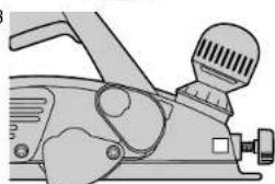
natural_image
Illustration of a mechanical device with a knob and lever mechanism (no text or symbols)PERILLA DE SEGURIDAD DE LA GUIA PARA BORDES
DW678,680/328494-01 1/13/00 11:25 AM Page 23
FIG. 11
natural_image
Illustration of a manual power tool with a wooden base and pipe (no text or symbols)Eje Lázaro Cárdenas No. 18 Local D, Col. Obrera 588-9377
MERIDA
Calle 63 #459-A (91 99) 23 54 90
MONTERREY
Av. Francisco I. Madero Pte. 1820-A (91 83) 72 11 25
PUEBLA
17 Norte #205 (91 22) 46 37 14
QUERETARO
Av. Madero 139 Pte. (91 42) 14 16 60
SAN LOUIS POTOSI
Pedro Moreno #100 Centro (91 48) 14 25 67
TORREON
Blvd. Independencia, 96 pte. (91 17) 16 52 65
VERACRUZ
Prolongación Diaz Miron #4280 (91 29) 21 70 16
VILLAHERMOSA
Constitucion 516-A (91 93) 12 53 17
DW678,680/328494-01 1/13/00 11:25 AM Page 24
Póliza de Garantía


- INSTRUCTION MANUAL GUIDE D'UTILISATION MANUAL DE INSTRUCCIONES
- General Safety Instructions
- SAVE THESE INSTRUCTIONS
- WORK AREA
- ELECTRICAL SAFETY
- PERSONAL SAFETY
- TOOL USE AND CARE
- SERVICE
- Additional Safety Instructions for Planers
- English
- Motor
- Operation
- SWITCH
- ADJUSTING PLANING DEPTH
- PLANING
- RABBETING
- How to Change and Adjust Carbide Blades (DW677, DW678) Fig. 9 - 12
- TO CHANGE BLADES
- How to Change Planer Blades (DW680)
- Setting the Adjustment Plate (Fig. 13)
- Parking Foot (Fig. 14)
- Edge Chamfering
- Cleaning & Lubrication
- Accessories
- Important
- Full Warranty
- DAY NO RISK SATISFACTION GUARANTEE
- REPLACEMENT DES LAMES
- Accessoires
- Póliza de Garantía
Brand : DEWALT
Model : DXIG3600E
Category : Generator