
CL30012 - Inverter e-ast - Free user manual and instructions
Find the device manual for free CL30012 e-ast in PDF.
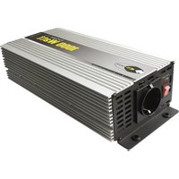
| Product Type | Inverter |
| Brand | e-ast |
| Model | CL30012 (CL300-12) |
| Nominal Input Voltage | 12 V DC |
| Output Voltage | 230 V AC ± 5% |
| Continuous Power | 300 W |
| Maximum Short-duration Power (0.3 s) | 600 W |
| Output Waveform | Modified Sine Wave |
| Output Frequency | 50 Hz ± 3% |
| USB Port | Yes, 5 V / 500 mA |
| Efficiency | 85% |
| No-load Current | ≤ 0.4 A |
| Undervoltage Warning | 11 V ± 0.5 V DC |
| Overvoltage Protection (fuse) | 1 x 40 A (flat fuse) |
| Overheat Protection | Shutdown > 70°C internal |
| Dimensions (L x W x H) | 212 x 106 x 59 mm |
| Weight | 0.75 kg |
| Operating Temperature Range | 0 °C to 40 °C |
| Relative Humidity (operation) | < 85% |
| Included Accessories | 1 set of cables with cigarette lighter plug and crocodile clips |
| EU Compliance | Low Voltage Directive 2006/95/EC, RoHS 2002/95/EC |
| Legal Warranty | Yes, date of purchase, subject to the instruction manual |
Frequently Asked Questions - CL30012 e-ast
User questions about CL30012 e-ast
0 question about this device. Answer the ones you know or ask your own.
Ask a new question about this device
Download the instructions for your Inverter in PDF format for free! Find your manual CL30012 - e-ast and take your electronic device back in hand. On this page are published all the documents necessary for the use of your device. CL30012 by e-ast.
USER MANUAL CL30012 e-ast
Series SL, CL, HPL - Modified Sine wave
Series CLS, HPLS - Pure Sine wave
Please read this user manual before operating the inverter!
Contents
Scope of Delivery 2
Accessories 2
General Information - Modified or Pure Sine Wave and USB-Port 3
Important Safety Information 3
Operating Environment 4
Cable. 4
Maintenance and Care 4
Children 4
Intended Usage 4
Important Information Regarding Usage 4
Connecting the Inverter 5
Connection with a Socket 5
Connection with a Starter or Supply Battery 5
Disconnecting the Connection to the Voltage source 5
Fuse Replacement 5f
Attachments
Troubleshooting 6
Technical Data 7f
In Case of Complaints 8
EG Compliance 8
For service related queries, please contact your dealer.
For all technical queries, we can be contacted for assistance through support@heicko.de.
© heicko 2015 - Duplication and reproduction of images, text and any other content, for anything other than purely private purposes requires our express written consent. We reserve the right to exercise our legal rights, to prevent the illegal use of the enclosed content.
This user manual is the original user manual in the German language. The term "Original User Manual" can only appear on the cover of this manual in other languages, if it has been authorized by us.
User manuals as well as other useful information (FAQ's) regarding our inverters can be found on our website www.heicko.de.
Subject to technical changes, printing errors and mistakes. Photos and other illustrations are not binding. Illustrations may vary from actual product depending on type and model.
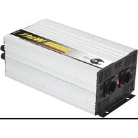
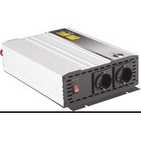
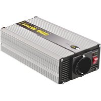
Scope of Delivery (Illustration)
Inverter - See type label
Cable set - See accessories
User manual
Accessories
SL series - Pre-installed cable set with cigarette lighter plug
CL, CLS series - 1 cable set each with cigarette lighter plug and crocodile clamps
HPL, HPLS series - 1 or 2 cable sets depending on type for secure fastening to the battery and to the inverter through screwing.
Attention: In case of damage or loss, the mentioned cable sets should be replaced with cables of similar quality and dimensions. Note, if improper replacements are used, a risk of fire exists (e.g. the cross-section being too short or too long).
Note: If cable replacements are not of a similar quality, the guarantee, as well as any damage claim in case of damages, is not valid.
Cable sets can be obtained from the relevant market.
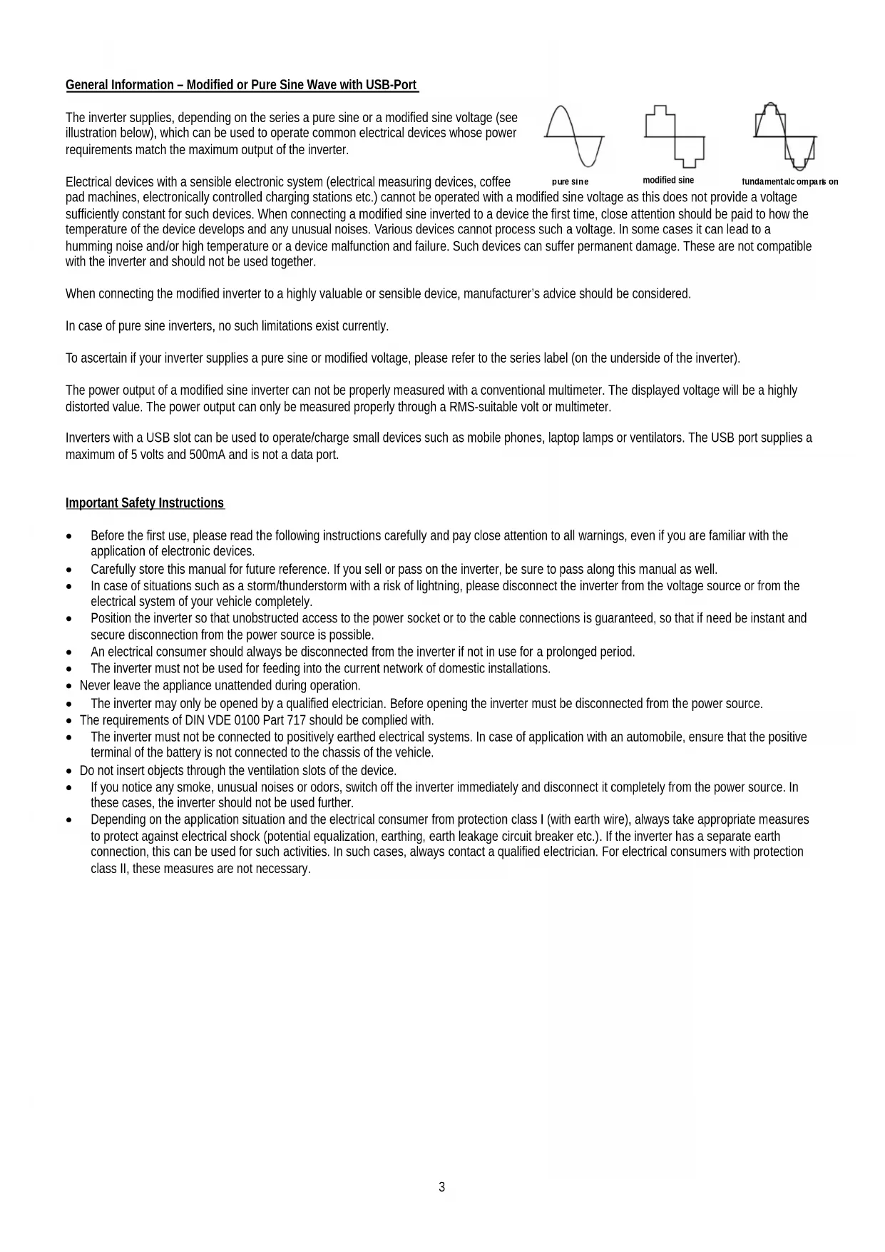
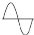
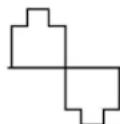
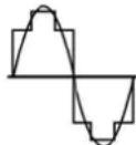
The inverter supplies, depending on the series a pure sine or a modified sine voltage (see illustration below), which can be used to operate common electrical devices whose power requirements match the maximum output of the inverter.
pure sine
modified sine
fundamental compaB on
Electrical devices with a sensible electronic system (electrical measuring devices, coffee
pad machines, electronically controlled charging stations etc.) cannot be operated with a modified sine voltage as this does not provide a voltage sufficiently constant for such devices. When connecting a modified sine inverted to a device the first time, close attention should be paid to how the temperature of the device develops and any unusual noises. Various devices cannot process such a voltage. In some cases it can lead to a humming noise and/or high temperature or a device malfunction and failure. Such devices can suffer permanent damage. These are not compatible with the inverter and should not be used together.
When connecting the modified inverter to a highly valuable or sensible device, manufacturer's advice should be considered.
In case of pure sine inverters, no such limitations exist currently.
To ascertain if your inverter supplies a pure sine or modified voltage, please refer to the series label (on the underside of the inverter).
The power output of a modified sine inverter can not be properly measured with a conventional multimeter. The displayed voltage will be a highly distorted value. The power output can only be measured properly through a RMS-suitable volt or multimeter.
Inverters with a USB slot can be used to operate/charge small devices such as mobile phones, laptop lamps or ventilators. The USB port supplies a maximum of 5 volts and 500mA and is not a data port.
Important Safety Instructions
Before the first use, please read the following instructions carefully and pay close attention to all warnings, even if you are familiar with the application of electronic devices.
- Carefully store this manual for future reference. If you sell or pass on the inverter, be sure to pass along this manual as well.
In case of situations such as a storm/thunderstorm with a risk of lightning, please disconnect the inverter from the voltage source or from the electrical system of your vehicle completely.
- Position the inverter so that unobstructed access to the power socket or to the cable connections is guaranteed, so that if need be instant and secure disconnection from the power source is possible.
An electrical consumer should always be disconnected from the inverter if not in use for a prolonged period.
- The inverter must not be used for feeding into the current network of domestic installations.
- Never leave the appliance unattended during operation.
The inverter may only be opened by a qualified electrician. Before opening the inverter must be disconnected from the power source.
The requirements of DIN VDE 0100 Part 717 should be complied with.
- The inverter must not be connected to positively earthed electrical systems. In case of application with an automobile, ensure that the positive terminal of the battery is not connected to the chassis of the vehicle.
- Do not insert objects through the ventilation slots of the device.
If you notice any smoke, unusual noises or odors, switch off the inverter immediately and disconnect it completely from the power source. In these cases, the inverter should not be used further.
- Depending on the application situation and the electrical consumer from protection class I (with earth wire), always take appropriate measures to protect against electrical shock (potential equalization, earthing, earth leakage circuit breaker etc.). If the inverter has a separate earth connection, this can be used for such activities. In such cases, always contact a qualified electrician. For electrical consumers with protection class II, these measures are not necessary.
Operating Environment
Place the inverter on a firm, level and temperature-resistant surface and avoid placing any heavy and/or combustible items on top of the inverter. Ensure that:
- Sufficient ventilation is provided at all times. Place the inverter in a position in which no ventilation slot is obstructed there is at least 10 cm clearance on all sides;
- No direct heat sources (e.g. heating) have an influence on the inverter;
- Direct sunlight and/or bright artificial light does not reach the inverter;
- Avoid contact with spray, dripping water and aggressive liquids do not operate the inverter in close proximity to water. In particular, the inverter must never be submerged. Do not place objects filled with liquids on or next to the inverter;
- The inverter should not be placed in the immediate vicinity of magnetic fields (e.g. loudspeakers);
- No open fire sources (e.g. burning candles) should be placed on or next to the device;
- Avoid intrusion from foreign matter (such as dust and other small particles);
- The inverter is not exposed to strong temperature fluctuations, otherwise condensation of air humidity can lead to a short-circuit;
The surrounding temperature should be maintained at between 0 - 40^
The air humidity during storage < 55% and in operation < 85% ; - Avoid exposing the inverter to excessive shocks and vibrations;
Cable
Fasten the cable always by the plug and do not pull the cord. Do not handle the cord with wet hands, as this may cause a short circuit or an electric shock. Do not place heavy objects on the inverter or the cable. Ensure that the cables are not bent, especially on the plug and on the connections eyelets/clamps. Never make knots in the cable and do not tie it together with other cables. All cables should be positioned so that nobody can step on or is disabled by the cables. Protect the cable from sharp-edged or pointed parts. If necessary, use conduits. A damaged cord can cause a fire or electric shock.
Check the power cord from time to time for damage and other changes. See also instructions under "Accessories".
Maintenance and Care
An expert examination is required if the inverter or any accessories have been damaged. Only authorized personnel should be allowed to carry out the inspection. Cleaning the device should only be carried out with a dry, clean cloth never with aggressive liquids/solutions. Do not attempt to open the inverter housing. Doing so would invalidate the warranty.
Children
Electrical devices do not belong in children's hands! Never let children operate electrical devices unsupervised. Children cannot always recognize possible dangers. Small parts can be life threatening, if swallowed. Keep the packing foil away from children's reach as there is a risk of suffocation.
Intended Usage
Depending on the type of the inverter, it is meant to be connected to either a 12V or a 24 V DC power source. This enables the inverter to supply 230V AC voltage for the operation of electrical device (only). The inverter is designed for private use, not suitable for commercial or industrial use. The inverter is by default not intended for medical, life saving or life sustaining purposes.
The inverter is not supposed to be used in tropical climates. Only those cables and external devices should be used which comply with the device's safety, electromagnetic and shielding specifications. This device complies with all the relevant CE requirements and standards. Compliance is not guaranteed, if any change to the inverter is carried out which is not approved by the manufacturer.
Important Information Regarding Usage
- Please pay close attention to the information regarding continuous output power and peak power. Devices with a higher connection value than the specified continuous power must not be operated on this inverter. The higher peak power can only cover short surge currents - for about 0.3 seconds.
- Pay attention to the audio alarm and the control lights. When the alarm sounds and the red warning light is illuminated, the capacity of the power source could be almost exhausted and the inverter is being supplied with a low voltage level. In such a case, turn off the connected equipment and disconnect from the power source. Use the inverter again only when the power source is recharged and able to supply the inverter with sufficient voltage.
Use only the cables delivered with the items. Inverters with two terminal pairs (units from 1500 W) should be connected with the accompanying two pairs of cables, since at maximum power the input current flow is extremely high. This requires the cross-section of both pair of wires. Otherwise, a risk of fire exists!
Connecting the inverter
Ensure that the power socket in the car or with in case of direct connection with a battery, the appropriate voltage (12V or 24V) is available. Never connect a 12V inverter to a power source of 24V as this will to irreparable damages.
A) Connection to a power socket (only for series SL, CL and CLS)
Depending on the fusing of the power socket's circuits, the inverter can be operated with 150-200 W. If you need the maximum continuous power of the inverter, the inverter must be directly connected with the battery through the battery cable - see below under "Connecting to a starter or battery supply".
- Make sure that no consumer is connected to the inverter, before you connect it to the power source. Make sure that the inverter is switched off (switch position "0").
- Remove the screws on the terminals. For this purpose, turn the screw counterclockwise until they are completely disconnected from the terminals. Remove the washers.
- Slide the eyelets of the connection cable on to the battery terminals. Pay close attention to the correct polarity. Insert the eyelet with the red mark on the red terminal (positive I + ) and the eyelet with the black mark on the black terminal (minus/).
- Insert the previously removed washer over the eyelets and screw the caps on the terminals. Turn the caps firmly so that the eyelets have full surface contact on the terminals.
- Plug the power cable into a suitable power socket.
- Connect the consumer to the inverters.
- Turn on the inverter (switch position "l").
- Turn on the consumer.
B) Connection to a starter or battery supply (all series except SL)
Series CL and CLS, battery cable with crocodile clamps and series HPL and HPLS, battery cable with eyelets for screwing.
-
For such a connection, ensure that the connection can be disconnected immediately in an emergency situation. In case of doubt, use approved disconnector/separator.
-
See A) 1.
- See A) 2.
- See A) 3.
- See A) 4.
- Connect the battery cable to the voltage source. Pay close attention to the polarity. Connect the red cable on the plus pole and the black battery cable to the minus pole.
- See A) 6.
- See A) 7.
- See A) 8.
Disconnecting the Connection to the Voltage Source
- Turn off the consumer and pull the plug from the socket of the inverter.
- Turn off the inverter (switch position "0").
- Remove the connection to the power source. To do this, remove the plug from the power socket, or disconnect the battery cables from the battery.
Attention! Always disconnect the black battery cable from the battery, and then the red cable. This avoids the risk of a short circuit.
Note: Disconnect the inverter when not in use completely from the power supply
Fuse Replacement
Attention! All replacement fuses have to be of the same value as the original. If the value is too low, the fuse can be triggered too soon. On the other hand, if the value is too high, the inverter can be damaged beyond repair and can cause a fire. The respective fuse values can be found in the technical data.
Glass fuse in the plug (only series SL, CL and CLS)
To replace the glass fuse in plug, unscrew the knurled cap in the front. Use a suitable tool if necessary. Turn the cap counterclockwise till it's completely unscrewed and then remove the fuse from the housing. Ensure no parts (knurled cap, pin, spring behind the fuse) are lost. Replace the fuse with a new one and then screw the cap back on to the housing.
Flat fuses (all series except SL)
Such fuses are located on the circuit board inside the housing. Hence, the housing needs to be opened for the replacement of the fuse. If in doubt, the replacement of such fuses should be carried out by a qualified electrician.
Attention! Before opening the housing, the inverter has to be disconnected from the power source. Otherwise there is a risk of electric shock.
The fuse is placed inside a plug-in system which is soldered to the circuit board and can be pulled out for replacement by using a suitable tool. Do not pull the fuse in a powerful jerking motion as this can remove the plug-in system from the circuit board. Pull the fuse out slowly and with gentle movements.
The housing should then be closed completely with all the fittings.
Attention! Do not operate the inverter if the housing is still open.
Note: All the fuses are from the automobile sector and commonly available in the relevant markets.
Attachments
Troubleshooting
No Output Voltage
Check whether the plug is firmly inserted in the power socket or the battery cables have firm a contact with the inverter and the battery.
Check the power supply to terminals of the inverter or for series SL on the board socket.
Check the position of the switch; it must be set to "I".
In case of overheating - see excess temperature.
Check device's fuse - see under Fuse Replacement
Alarm sounds (indicates one of the following states)
Excess Temperature:
The overheating protection is activated and the inverter has been switched off (red LED lights up). Switch off the inverter and allow it to cool for about 30 minutes before it can be operated again.
Under voltage:
The battery has too low voltage. Charge the battery before further operation. In case of under voltage, the red LED lights up.
Overload:
The input power requirement of the electrical consumer is higher than the maximum continuous power output of the inverter. Reduce consumer load.
The Red LED Lights Up:
There is excess voltage at the inverter input e.g. a 12V inverter is connected to the 24V socket of a lorry. Turn off the inverter immediately and disconnect from the power source.
Technical Data Series SL and CL
| Item description SL150-A-12 CL300-12 CL300-24 CL500-12CL500-24 CL600-12 CL600-24CL700-D-12 CL700-D-24 | ||||||||||
| Rated Input Voltage [V] 12 12 24 12 24 12 24 12 | 24 12 24 | |||||||||
| Rated/Continuous Power [W] | 150 300 | 500 600 700 | ||||||||
| Short-term Peak Power [W] (0.3 sec) | 300 600 | 1000 1200 1400 | ||||||||
| Input Voltage Range [V] DC 11 V-15 V 11 V-15 V 22 V-30 V 11 V-15 V 22 V-30 V 11 V-15 V 22 V-30 V | ||||||||||
| Rated Input Current[A] | 14.7 29.4 | 14.7 49 24.5 58 | 8 29.4 68.6 34.3 | |||||||
| Output Voltage [V] AC | 230 V ± 5% | 230 V ± 5% | 230 V ± 5% | 230 V ± 5% | 230 V ± 5% | |||||
| Frequency [Hz] | 50 Hz ± 3% | 50 Hz ± 3% | 50 Hz ± 3% | 50 Hz ± 3% | 50 Hz ± 3% | |||||
| Rated Output Current[A] AC | 0.7 | 1.3 | 2.2 | 2.6 | 3 | |||||
| Output Wave Form | modified sine | modified sine | modified sine | modified sine | modified sine | |||||
| Efficiency | 85% 85% | 85% | 85% | 85% | ||||||
| Idle Current[A] | ≤0.35 A | ≤0.4 A | ≤0.3 A | ≤0.4 A | ≤0.3 A | ≤0.5 A | ≤0.4 A | ≤0.6 A | ≤0.5 A | |
| Low Voltage Warning [V] DC | 11 V±0.5 V | 11 V±0.5 V | 22 V±1 V | 11 V±0.5 V | 22 V±1 V | 11 V±0.5 V | 22 V±1 V | 11 V±0.5 V | 22 V±1 V | |
| Excess Current Protection [A] DC (Fuses) | 1 x 20 | 1 x 40 | 1 x 20 | 2 x 30 | 1 x 30 | 2 x 35 | 1 x 35 | 2 x 40 | 1 x 40 | |
| USB Port (Rated Values) | 5 V, 500 mA | 5 V, 500 mA | - | - | - | - | 5 V, 500 mA | |||
| Overheating Warning (Internal) | >65°C | |||||||||
| Switching -Off When Excess Heat (Internal) | >70°C | |||||||||
| Dimensions (L x B x H) [cm] | 180 x 73 x 73 | 212 x 106 x 59 | 240 x 110 x 60 | 240 x 110 x 60 | 225 x 150 x 70 | |||||
| Weight[kg] | 0.49 0.75 | 0.95 0.95 1.5 | ||||||||
Technical Data Series HPL
| Item description | HPL1200-D-12 | HPL1200-D-24 | HPL2000-12 | HPL2000-12 | HPL3000-12 | HPL3000-24 | HPL5000-24 |
| Rated Input Voltage [V] | 12 | 24 | 12 | 24 | 12 | 24 | 24 |
| Rated/Continuous Power [W] | 1200 | 2000 | 3000 | 5000 | |||
| Short-term Peak Power [W] (0.3 sec) | 2400 | 4000 | 6000 | 10000 | |||
| Input Voltage Range [M DC] | 11 V-15 V | 22 V-30 V | 11 V-15 V | 22 V-30 V | 11V-15V | 22V-30 V | 22 V-30 V |
| Rated Input Current[A] | 117,6 | 58,8 | 196,1 | 98 | 294,1 | 147,1 | 245,1 |
| Output Voltage [V] AC | 230 V ± 5% | 230 V ± 5% | 230 V ± 5% | 230 V ± 5% | |||
| Frequency [Hz] | 50 Hz ± 3% | 50 Hz ± 3% | 50 Hz ± 3% | 50 Hz ± 3% | |||
| Rated Output Current[A] AC | 5,2 | 8,7 | 13 | 21,7 | |||
| Output Wave Form | modified sine | modified sine | modified sine | modified sine | |||
| Efficiency | 85% | 85% | 85% | 85% | |||
| Idle Current[A] | ≤0.8 A | ≤0.6 A | ≤1.0 A | ≤0.8 A | ≤1.2 A | ≤1 A | ≤3 A |
| Low Voltage Warning [V] DC | 11 V±0.5 V | 22 V±1 V | 11 V±0.5 V | 22 V±1 V | 11 V±0.5 V | 22 V±1 V | 22 V±1 V |
| Excess Current Protection [A] DC (Fuses) | 4 x 35 | 2 x 35 | 8 x 30 | 4 x 30 | 12 x 30 | 6 x 30 | 10 x 30 |
| USB Port (Rated Values) | 5 V, 500 mA | - | - | - | - | - | |
| Overheating Warning (Internal) | >65°C | ||||||
| Switching -Off When Excess Heat(Internal) | >70°C | ||||||
| Dimensions (L x B x H) [cm] | 335 x 155 x 70 | 420 x 200 x 70 | 400 x 200 x 140 | 515x205x155 | |||
| Weight[kg] | 2,41 | 4,68 | 6,6 | 8 | |||
Technical Data Series CLS
| Item description | CLS300-12 | CLS300-24 | CLS600-12 | CLS600-24 |
| Rated Input Voltage [V] | 12 | 24 | 12 | 24 |
| Rated/Continuous Power [W] | 300 | 600 | ||
| Short-term Peak Power [W] (0.3 sec) | 600 | 1200 | ||
| Input Voltage Range [M DC | 11 V-15 V | 22 V-30 V | 11 V-15 V | 22 V-30 V |
| Rated Input Current[A] | 29,4 | 14,7 | 58,8 | 29,4 |
| Output Voltage [V] AC | 230 V ± 5% | |||
| Frequency [Hz] | 50 Hz ± 3% | |||
| Rated Output Current[A] AC | 1,3 | 1,3 | 2,6 | 2,6 |
| Output Wave Form | pure sine | |||
| Efficiency | 85% | 85% | ||
| Idle Current[A] | <0.5 A | <1.0 A | ||
| Low Voltage Warning [M DC | 10,5 | 21 | 10,5 | 21 |
| Excess Current Protection [A] DC (Fuses) | 1 x 40 | 1 x 20 | 2 x 35 | 1 x 35 |
| USB Port (Rated Values) | >65°C | |||
| Overheating Warning (Internal) | >70°C | |||
| Switching-Off When Excess Heat (Internal) | 220 x 108 x 60 | 255 x 108 x 60 | ||
| Dimensions (L x B x H) [cm] | 1,2 | 1,6 | ||
| Weight[kg] | ||||
Technical Data Series HPLS
| Item description HPLS1000-12 HPLS1000-24 HPLS100-12 HPLS1500-24 HPLS2000-12 HPLS2000-24 | ||||||
| Rated Input Voltage [V] 12 24 12 24 12 24 | ||||||
| Rated/Continuous Power [W] | 1000 1500 2000 | |||||
| Short-term Peak Power [W] (0.3 sec) | 2000 3000 4000 | |||||
| Input Voltage Range [V] DC 11 V-15 V 22 V-30 V 11 V | 15 V 22 V-30 V 11 V-15 V 22 V-30 V | |||||
| Rated Input Current[A] | 98 49 147 78.5 196 98 | |||||
| Output Voltage [V] AC 230 V ± 5% | ||||||
| Frequency [Hz] 50 Hz ± 3% | ||||||
| Rated Output Current[A] AC | 4,35 | 4,35 | 6,52 | 6,52 8 | ,7 | 8,7 |
| Output Wave Form | pure sine | |||||
| Efficiency | 85% 85% 85% | |||||
| Idle Current[A] | <1,5 A <1,5 A <1,5 A | |||||
| Low Voltage Warning [V] DC | 10,5 | 21 | 10,5 | 21 | 10,5 | 21 |
| Excess Current Protection [A] DC (Fuses) | 3 x 40 | 3 x 20 | 4 x 40 | 4 x 20 | 6 x 40 | 6 x 20 |
| USB Port (Rated Values) | >65°C | |||||
| Overheating Warning (Internal) | >70°C | |||||
| Switching-Off When Excess Heat(Internal) | 335 x 135 x 72 | 370 x 200 x 75 | 395 x 200 x 75 | |||
| Dimensions (L x B x H) [cm] | 2,9 | 5 | 6 | |||
| Weight[kg] | ||||||
In Case Of Complaints
Please note the following:
The statutory warranty applies from the date of purchase. Please keep the invoice / receipt as proof of purchase. Contact your dealer in case of a complaint/warranty issue. Only in this way, the matter can be handled smoothly.
- Without proof of purchase, there is no warranty claim.
In case of repairs, there is no right to a replacement device for the duration of the repairs.
A warranty claim for defects and damages of any kind, even those that did not occur to the delivered item itself is excluded, which arise from non-compliance with this manual and the safety instructions, faulty installation and connection, improper use as well as incorrect operation and improper transport. Wear and tear damage thereby is also excluded from the warranty.
There is no warranty if repairs or modifications have been carried out by entities other than the manufacturer or a customer service personnel authorized by the manufacturer.
The cost of installing and removing proven defective inverters are excluded from the fulfillment of claim pursuant to 439 paragraph 1 BGB. Exception to this applies only to the sale of consumer goods in accordance with 474 BGB. However, if a contract exists between the companies, the supplementary performance variant "delivery of a defect-free thing," in addition to the removal and transport of the defective good cannot be claimed against the installing of the delivered replacement.
The statutory provisions regarding the warranty should be complied with.
The general terms and conditions should be complied with.
EG Compliance
We hereby declare that the product "Inverter" referred to in the technical specifications, complies with the EC directives listed below:
Low Voltage Directive 2006/95 / EC EMC Directive 2004/108 / EC
The products therefore carry the compliance symbol.

The product also complies with RoHS directive 2002/95 / EC
Disposal of old and faulty equipment
Electrical and electronic devices should not be disposed of with household garbage! Electrical devices must be disposed of through a municipal collection point or by using an optionally offered removal service for electrical and electronic equipment.
Directive CEM2004/108/CE

- Contents
- Scope of Delivery (Illustration)
- Accessories
- Important Safety Instructions
- Operating Environment
- Cable
- Maintenance and Care
- Children
- Intended Usage
- Important Information Regarding Usage
- Connecting the inverter
- Disconnecting the Connection to the Voltage Source
- Fuse Replacement
- Glass fuse in the plug (only series SL, CL and CLS)
- Flat fuses (all series except SL)
- Attachments
- Troubleshooting
- Technical Data Series HPLS
- In Case Of Complaints
- EG Compliance
- Disposal of old and faulty equipment
Brand : e-ast
Model : CL30012
Category : Inverter