
Helix 12 Chirp SI GPS - Fish finder HUMMINBIRD - Free user manual and instructions
Find the device manual for free Helix 12 Chirp SI GPS HUMMINBIRD in PDF.
| Product Type | Fish finder with sonar, side imaging and GPS |
| Brand | Humminbird |
| Model | Helix 12 Chirp SI GPS |
| Screen Size | 12 inches (diagonal) |
| Sonar Technology | CHIRP, Side Imaging, Down Imaging |
| Integrated GPS | Yes, with GPS reception and mapping |
| Power Supply | 12 V DC, 5 A fuse (time-delay) |
| Power Cable Length | 2 m (6 ft) |
| Mounting | Gimbal bracket with removable cable tray |
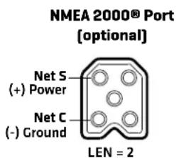
| Number of Ports | Power, transducer, Ethernet, NMEA 2000, accessories |
| Approximate Weight | 2.5 kg (estimate) |
| Approximate Dimensions | 350 x 250 x 100 mm (estimate) |
| Waterproof Class | Designed for marine environment, splash resistant |
| Operating Temperature | -15 °C to 55 °C (estimate) |
| Included Accessories | Gimbal bracket, screws, washers, installation guide |
| Main Functions | CHIRP sonar, Side Imaging, Down Imaging, GPS, mapping, depth alarms |
| Maintenance and Cleaning | Clean with soft cloth and fresh water, avoid solvents |
| Safety | Do not use as primary navigation device, disconnect power before maintenance |
| Spare Parts and Repairability | Repair only by authorized personnel, warranty void if unauthorized disassembly |
| General Information | FCC Class B compliant, WEEE directive, manufactured by Johnson Outdoors |
Frequently Asked Questions - Helix 12 Chirp SI GPS HUMMINBIRD
User questions about Helix 12 Chirp SI GPS HUMMINBIRD
0 question about this device. Answer the ones you know or ask your own.
Ask a new question about this device
Download the instructions for your Fish finder in PDF format for free! Find your manual Helix 12 Chirp SI GPS - HUMMINBIRD and take your electronic device back in hand. On this page are published all the documents necessary for the use of your device. Helix 12 Chirp SI GPS by HUMMINBIRD.
USER MANUAL Helix 12 Chirp SI GPS HUMMINBIRD
HELIX® SERIES CONTROL HEAD Installation Guide
532405-6_B
Follow the instructions in this installation guide to gimbal mount the control head.

NOTE: Your gimbal bracket may not look exactly like the gimbal bracket shown in the illustrations, but it will mount in exactly the same way.
| INSTALLATION PREPARATION |
| Read the instructions in this transducer guide completely to understand the mounting guidelines before starting the installation. |
| Visit our Web site at humminbird.com for additional information and resources for transducer installations. Also, visit youtube.com/humminbirdtv for informational videos. |
| Supplies: In addition to the hardware supplied with your control head, you will need a powered hand drill and various drill bits, Phillips head screwdriver, flat head screwdriver, pencil, safety glasses and dust mask, marine-grade silicone sealant, dielectric grease [optional], extension cables [optional], Ethernet cables [optional], and accessory cables [optional]. Also, see Connect Power to determine the type of connection, fuse size, and additional equipment you will need for the installation. |
| Accessories and Ethernet: Accessories and Ethernet equipment are available for purchase at humminbird.com. The installation guides are available with the product, or they can be downloaded from our Web site. |
INSTALLATION OVERVIEW
1 | Plan the Mounting Location
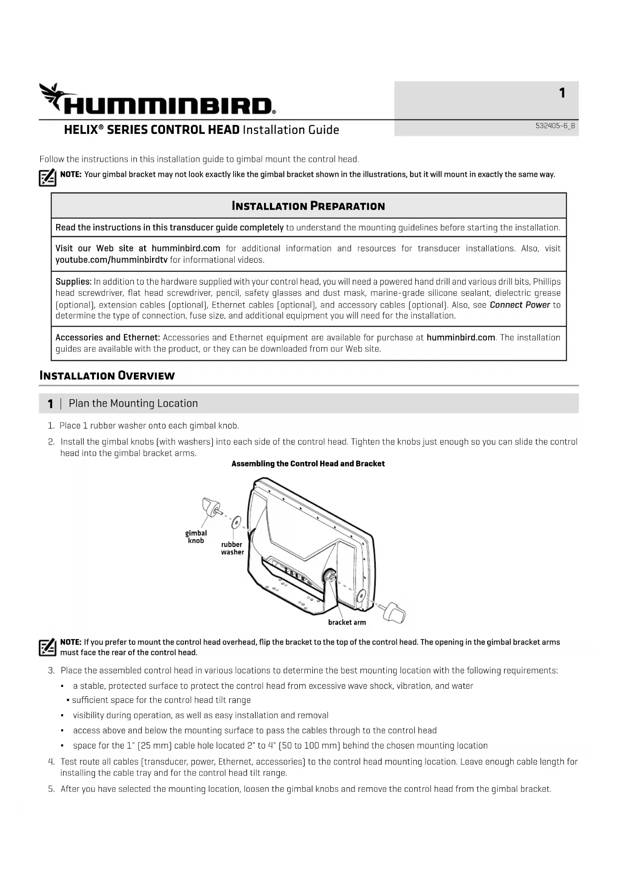
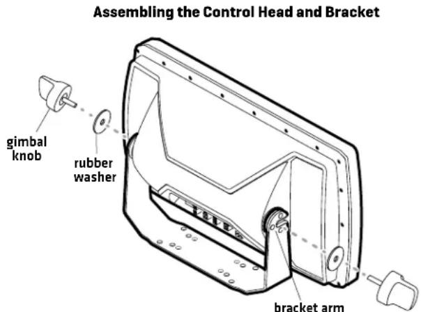
- Place 1 rubber washer onto each gimbal knob.
- Install the gimbal knobs (with washers) into each side of the control head. Tighten the knobs just enough so you can slide the control head into the gimbal bracket arms.

NOTE: If you prefer to mount the control head overhead, flip the bracket to the top of the control head. The opening in the gimbal bracket arms must face the rear of the control head.
-
Place the assembled control head in various locations to determine the best mounting location with the following requirements:
-
a stable, protected surface to protect the control head from excessive wave shock, vibration, and water
- sufficient space for the control head tilt range
- visibility during operation, as well as easy installation and removal
- access above and below the mounting surface to pass the cables through to the control head
-
space for the 1" [25 mm] cable hole located 2" to 4" [50 to 100 mm] behind the chosen mounting location
-
Test route all cables (transducer, power, Ethernet, accessories) to the control head mounting location. Leave enough cable length for installing the cable tray and for the control head tilt range.
- After you have selected the mounting location, loosen the gimbal knobs and remove the control head from the gimbal bracket.
HELIX® SERIES CONTROL HEAD Installation Guide
532405-6_B
2 | Install the Gimbal Bracket
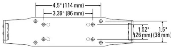
- Place the gimbal bracket in the chosen position on the mounting surface. Mark the four outer mounting screw locations using a pencil or center punch.

NOTE: The outer set of mounting holes is recommended. You may use the inside set of mounting holes if necessary. There may be additional, unused mounting holes on the gimbal bracket.
- Set the gimbal bracket aside. Drill the four mounting screw holes using a 5/32" [4 mm] drill bit.
- Cable Hole: Mark and drill a 1" [25 mm] hole 2" to 4" [50 to 100 mm] behind the bracket. You will use this hole for routing the cables to the control head in another section.
- Place the bracket on the mounting surface aligned with the drilled holes. Fill the mounting holes with marine-grade silicone sealant.
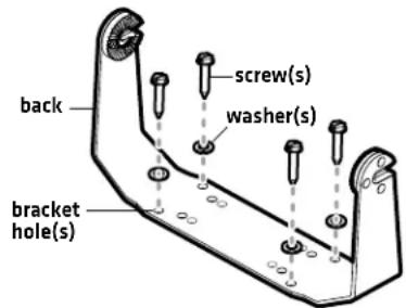
- Place one flat washer onto each #10 x 1" wood screw. Insert the four screws with washers into the mounting holes [see the illustration Installing the Gimbal Bracket]. Hand tighten only!
Bracket Hole Pattern Measurements
3 | Connect Power
It is important to review the following information before you start the power installation:
- Cable Length: A 6' (2 m) long power cable is included. You may shorten or lengthen the cable using 18 gauge multi-stranded copper wire. See the Recommended Power Cable Extension Information table for details.
Recommended Power Cable Extension Information
| Extension Length Wire Gauge | |
| 1 to 6 ft 18 AWG | |
| 6 to 12 ft 14 AWG | |
| 12 to 24 ft 12 AWG | |
Please consult a U.S. Coast Guard ABYC-approved wire gauge diagram or a certified NMEA Marine Electronics Installer.
- Power Supply: The control head must be connected to a 12 VDC power supply using the fuse size shown in the Required Fuse Size table.
Required Fuse Size
| Model Fuse Size Fuse Type | |
| HELIX 7 3A slow-blow or MDL equivalent | |
| HELIX 8 5A slow-blow or MDL equivalent | |
| HELIX 9 5A slow-blow or MDL equivalent | |
| HELIX 10 5A slow-blow or MDL equivalent | |
| HELIX 12 5A slow-blow or MDL equivalent | |
| HELIX 15 7.5A slow-blow or MDL equivalent | |
Installing the Gimbal Bracket
HELIX® SERIES CONTROL HEAD Installation Guide
532405-6_B
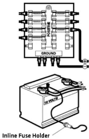
- Fuse Panel or Battery: The control head power cable can be connected to the electrical system of the boat at the fuse panel (usually located near the console), or directly to the battery. In order to minimize the potential for interference with other marine electronics, a separate power source (such as a second battery) may be necessary.
WARNING! Some boats have 24 or 36 Volt electric systems, but the control head MUST be connected to a 12 VDC power supply.
WARNING! Make sure that the power cable is disconnected from the control head at the beginning of this procedure.
WARNING! Humminbird® is not responsible for over-voltage or over-current failures. The control head must have adequate protection through the proper selection and installation of the fuse size shown in the Required Fuse Size table.
- Confirm that the power cable is disconnected from the control head.
- Connect the power cable wires to the fuse panel or battery as follows:
Fuse Terminal Connection: Use crimp-on type electrical connectors (not included) that match the terminal on the fuse panel. Attach the black wire to ground [-], and the red wire to positive (+) 12 VDC power. Install the required fuse (as shown in the Required Fuse Size table).
Battery Connection: Install an inline fuse holder [not included] and the required fuse [as shown in the Required Fuse Size table]. Attach the black wire to ground [-], and the red wire to positive (+) 12 VDC power.
NOTE: For multi-control head installations and troubleshooting information, download the Power Troubleshooting Guide from our Web site at humminbird.com. Also, see the Operations Summary Guide to set the Low Battery Alarm and use Standby Mode to conserve power.
NOTE: If you have a trolling motor, it is important to keep the control head power and trolling motor power as separate as possible.
4 | Route the Cables to the Control Head
- Sonar: Proceed to your transducer installation guide and follow the instructions to install the transducer.
- Accessories [optional]: Install accessories using the guides provided with them.
- Ethernet [optional]: Install Ethernet cables and hardware using the Ethernet Installation Guide.

NOTE: The installation guides for Ethernet and optional-purchase accessories are available with your product, and they can be downloaded from our Web site at humminbird.com.
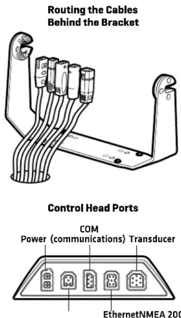
- Route all cables to the control head. Your boat may have a pre-existing wiring channel or conduit that you can follow. Route the cables as far as practical from the antenna cable of VHF radios or tachometer cables to reduce the possibility of interference.

CAUTION! Do NOT mount the cables where the connectors could be submerged in water or flooded. If cables are installed in a splash-prone area, it may be helpful to apply dielectric grease to the inside of the connectors to prevent corrosion. Dielectric grease can be purchased separately from a general hardware or automotive store.
- Pass the cables through the cable hole.
- For HELIX 7 control heads, insert the cable connectors into the correct ports on the control head and proceed to Section 6. Secure the Control Head Installation. For all other models, proceed to Section 5. Assemble the Cable Tray.
HELIX® SERIES CONTROL HEAD Installation Guide
532405-6_B
5 | Assemble the Cable Tray
The cable tray is an important part of the control head installation. It secures the cables and protects them from potential damage.
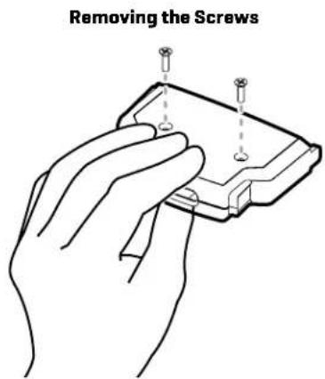
- Use a Phillips head screwdriver to remove the screws from the bottom of the cable tray.
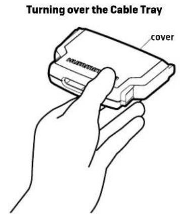
- Hold the cable tray together and turn it over, so the Humminbird logo is facing up. Lift the cover and set it aside.
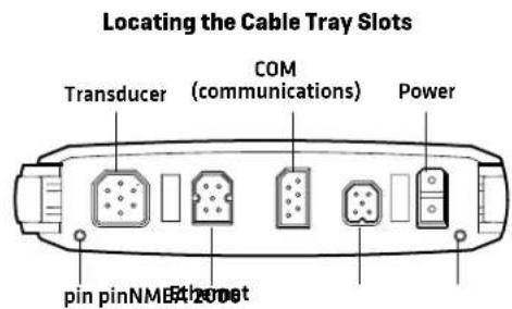
- See the illustration Locating the Cable Tray Slots. Insert each cable connector into the correct slots in the tray.
Each slot is shaped specifically for each connector, and insertion should be easy. Route the cables using the grooves in the tray.
Inserting the Cable Connectors into the Cable Tray
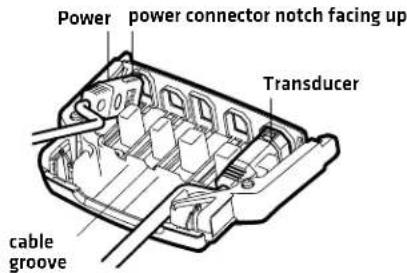
CAUTION! It is important to place the connectors into the correct slots and right side up. See the illustration Locating the Cable Tray Slots for details.
-
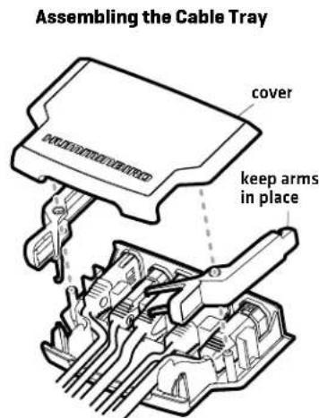
Place the cover onto the tray. Hold the tray together and turn it over.
If the cable tray arms fall out, see the illustration Assembling the Cable Tray to put them back in place. -
Install the screws in the holes on the bottom of the tray. Hand tighten only. See the illustration. Removing the Screws to replace the screws. Hand tighten only.
-
Turn over the cable tray so the Humminbird logo is facing up.
Confirm the cables hang straight, and untwist them if necessary.
- Line up the slots on the cable tray with the matching ports on the back of the control head. Line up the cable tray pins with the holes on the control head [see the illustration Locating the Cable Tray Slots].
With the Humminbird logo facing up, plug the cable tray into the back of the control head. The cable tray clasps should click into place. See the illustration Connecting the Cable Tray to the Control Head.
HELIX® SERIES CONTROL HEAD Installation Guide
532405-6_B
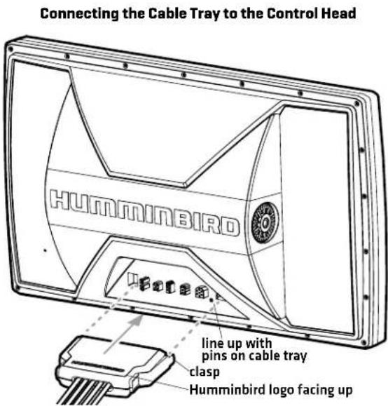
- Pull carefully on the cable tray to confirm the installation is secure. Make sure both clasps clicked into place in step 7.
6 | Secure the Control Head Installation
- Slide the control head into the bracket.
- Confirm there is enough cable slack to allow for the control head to pivot through its full tilt range and for connecting or disconnecting the cables.
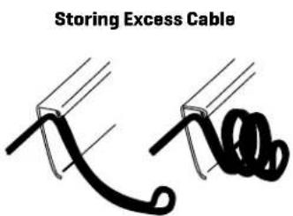
NOTE: If there is excess cable that needs to be gathered at one location, dress the cable routed from both directions so that a single loop is left extending from the storage location. Doubling the cable up from this point, form the cable into a coil. Storing excess cable using this method can reduce electronic interference. - Adjust the control head to the viewing angle you prefer. Hand tighten the gimbal knobs until the assembly is secured. Hand tighten only!
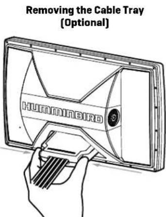
Remove the Cable Tray [Optional]: Squeeze the sides of the cable tray until it releases.

7 | Test the System Installation
- Press the POWER key to turn on the control head.
- While the Title screen is shown on the display, press the MENU key.
- Press the DOWN Cursor key to choose System Status, and press the RIGHT Cursor key to select it.
NOTE: If you wait too long, the system will automatically start whichever menu is highlighted, and you will have to start again. - Accessories: Press the VIEW key. Review the Accessory Test View to confirm accessories are listed as connected.
- GPS Reception: Press the VIEW key. Review the GPS Diagnostic View and confirm that a latitude/longitude position is displayed and the Fix Type is listed as Enhanced or 3D.
- Power Off: Press and hold the POWER key to power off the unit.
- Sonar Test: Test and finalize the transducer installation using the instructions in the transducer installation guide. When the transducer test and installation are completed, your control head is ready for on-the-water operation. When you power on the control head, it will start Normal mode automatically if a functioning transducer is detected.


NOTE: For operations information, see the Operations Summary Guide included with your control head and the control head operations manual (available for download at humminbird.com).
Contact Humminbird
Contact Humminbird Technical Support through our Help Center at https://humminbird-help.johnsonoutdoors.com/hc/en-us or in writing to the address below:
Humminbird Service Department
678 Humminbird Lane
Eufaula, AL 36027 USA
WARNING! Disassembly and repair of this electronic unit should only be performed by authorized service personnel. Any modification of the serial number or attempt to repair the original equipment or accessories by unauthorized individuals will void the warranty.
WARNING! This device should not be used as a navigational aid to prevent collision, grounding, boat damage, or personal injury. When the boat is moving, water depth may change too quickly to allow time for you to react. Always operate the boat at very slow speeds if you suspect shallow water or submerged objects.
FCC NOTICE: This device complies with Part 15 of the FCC Rules. Operation is subject to the following two conditions: [1] this device may not cause harmful interference, and [2] this device must accept any interference received, including interference that may cause undesired operation.
CAUTION! This equipment has been tested and found to comply with the limits for a Class B digital device, pursuant to Part 15 of the FCC Rules. These limits are designed to provide reasonable protection against harmful interference in a residential installation. This equipment generates, uses and can radiate radio frequency energy and, if not installed and used in accordance with the instructions, may cause harmful interference to radio communications. However, there is no guarantee that interference will not occur in a particular installation. If this equipment does cause harmful interference to radio or television reception, which can be determined by turning the equipment off and on, the user is encouraged to try to correct the interference by one or more of the following measures:
- Reorient or relocate the receiving antenna.
- Increase the separation between the equipment and receiver.
- Connect the equipment into an outlet on a circuit different from that to which the receiver is connected.
- Consult the dealer or an experienced radio/TV technician for help.
ENVIRONMENTAL COMPLIANCE STATEMENT: It is the intention of Johnson Outdoors Marine Electronics, Inc. to be a responsible corporate citizen, operating in compliance with known and applicable environmental regulations, and a good neighbor in the communities where we make or sell our products.
WEEE DIRECTIVE: EU Directive 2002/96/EC "Waste of Electrical and Electronic Equipment Directive [WEEE]" impacts most distributors, sellers, and manufacturers of consumer electronics in the European Union. The WEEE Directive requires the producer of consumer electronics to take responsibility for the management of waste from their products to achieve environmentally responsible disposal during the product life cycle.
WEEE compliance may not be required in your location for electrical & electronic equipment [EEE], nor may it be required for EEE designed and intended as fixed or temporary installation in transportation vehicles such as automobiles, aircraft, and boats. In some European Union member states, these vehicles are considered outside of the scope of the Directive, and EEE for those applications can be considered excluded from the WEEE Directive requirement.
This symbol [WEEE wheelie bin] on product indicates the product must not be disposed of with other household refuse. It must be disposed of and collected for recycling and recovery of waste EEE.
Johnson Outdoors Marine Electronics, Inc. will mark all EEE products in accordance with the WEEE Directive. It is our goal to comply in the collection, treatment, recovery, and environmentally sound disposal of those products; however, these requirements do vary within European Union member states. For more information about where you should dispose of your waste equipment for recycling and recovery and/or your European Union member state requirements, please contact your dealer or distributor from which your product was purchased.
TÊTE DE COMMANDE DE LA SÉRIE HELIX Guide d'Installation
532405-6_B
natural_image
Technical line drawing of a mechanical or electrical component with multiple cylindrical components and mounting brackets (no text or symbols)natural_image
Line drawing of a hand holding a small electronic component with three pins inserted (no text or symbols)natural_image
Two black cable or wire diagrams with no text or symbolsTÊTE DE COMMANDE DE LA SÉRIE HELIX Guide d'Installation
532405-6_B
Humminbird Service Department
678 Humminbird Lane
Eufaula, AL 36027 USA