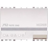
20421.B - Detector Vimar - Free user manual and instructions
Find the device manual for free 20421.B Vimar in PDF.



| Product type | Gas detector (LPG or methane) |
| Brand | Vimar |
| Model | 20421.B (Gas Stop LPG) |
| Power supply | 230 V~ ±10%, 50-60 Hz |
| Sensor type | Tin dioxide semiconductor with physical filter |
| Alarm threshold | 9% LEL (isobutane for LPG) |
| Optical indication | Green LED (on), yellow (fault/disconnection), red (alarm) |
| Acoustic indication | Piezoelectric buzzer 85 dB at 1 m |
| Outputs | Terminals 6-7 for 12 V DC solenoid valve (Vimar 16590 or equivalent); terminals 3-4-5 changeover relay (5 A 250 V~) |
| Lifespan | 5 years (flush-mounted), up to 10 years (surface-mounted with sensor replacement at 5 years) |
| Operating temperature | -10 °C to +40 °C |
| Relative humidity | 30-90% non-condensing |
| Protection rating | IP40 (flush-mounted), IP42 (surface-mounted) |
| Housing material | Self-extinguishing polycarbonate |
| Compliance | LV and EMC directives, standards EN 50270, IEC 216-8 (flush-mounted), EN 50194-1 (surface-mounted) |
| Installation | Height: 20-30 cm from floor (LPG) or from ceiling (methane); max distance 3-4 m from source |
| Maintenance | Cleaning with damp cloth; periodic test with Vimar 01899 test gas |
| Spare parts | Internal sensor Vimar 01895.G (LPG) or 01896.M (methane) for wall-mounted models |
| Safety | Double insulation between 230 V~ and 12 V DC output; short-circuit protection |
| Dimensions (flush-mounted) | Suitable for Eikon, Arké, Idea, Plana, 8000 series |
| Power consumption | Not specified |
| Weight | Not specified |
Frequently Asked Questions - 20421.B Vimar
User questions about 20421.B Vimar
0 question about this device. Answer the ones you know or ask your own.
Ask a new question about this device
Download the instructions for your Detector in PDF format for free! Find your manual 20421.B - Vimar and take your electronic device back in hand. On this page are published all the documents necessary for the use of your device. 20421.B by Vimar.
USER MANUAL 20421.B Vimar
To be filled in by the installer
Date of installation
Date d'installation
Installationsdatum
Surface mounting devices: sensor replaceable date
Gas Stop GPL, electronic LPG detector with acoustic and optical signalling and direct control on solenoid valve, supply voltage 230V 50 - 60Hz
Gas Stop Metano, electronic methane detector with acoustic and optical signalling and direct control on solenoid valve, supply voltage 230V 50 - 60Hz
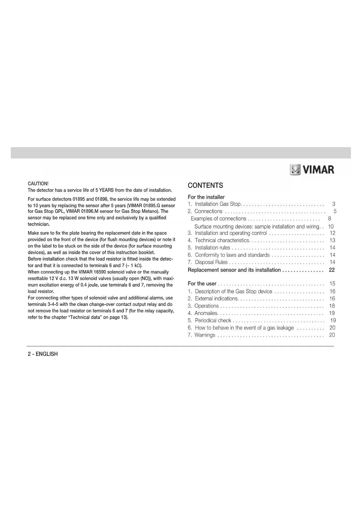
The detector has a service life of 5 YEARS from the date of installation.
For surface detectors 01895 and 01896, the service life may be extended to 10 years by replacing the sensor after 5 years (VIMAR 01895.G sensor for Gas Stop GPL, VIMAR 01896.M sensor for Gas Stop Metano). The sensor may be replaced one time only and exclusively by a qualified technician.
Make sure to fix the plate bearing the replacement date in the space provided on the front of the device (for flush mounting devices) or note it on the label to be stuck on the side of the device (for surface mounting devices), as well as inside the cover of this instruction booklet.
Before installation check that the load resistor is fitted inside the detector and that it is connected to terminals 6 and 7 (~1 kΩ).
When connecting up the VIMAR 16590 solenoid valve or the manually resettable 12V d.c. 13 W solenoid valves (usually open (NO)), with maximum excitation energy of 0.4 joule, use terminals 6 and 7, removing the load resistor.
For connecting other types of solenoid valve and additional alarms, use terminals 3-4-5 with the clean change-over contact output relay and do not remove the load resistor on terminals 6 and 7 (for the relay capacity, refer to the chapter "Technical data" on page 13).

VIMAR
CONTENTS
For the installer
- Installation Gas Stop.. 3
- Connections 5
Examples of connections 8
Surface mounting devices: sample installation and wiring. 10
- Installation and operating control 12
- Technical characteristics.. 13
- Installation rules 14
- Conformity to laws and standards 14
- Disposal Rules 14
Replacement sensor and its installation 22
For the user 15
1.Description of the Gas Stop device 16
2. External indications.. 16
3. Operations 18
4.Anomalies. 19
5.Periodical check. 19
6. How to behave in the event of a gas leakage 20
7.Warnings 20
For the installer
1. Installation Gas Stop
Apply to authorized technicians for all installation and any routine and non-routine maintenance operation as well as for the replacement of the detector at the end of its life-time.
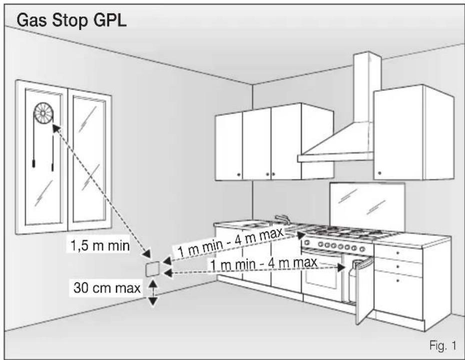
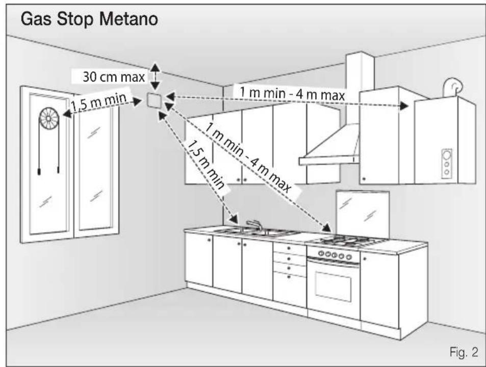
The LPG/methane detector must be installed in a position in which air circulates freely, at a distance of no more than 3 - 4m from boilers, water heaters, stoves and gas canisters and at 20 - 30cm above floor level (figure 1 - Gas Stop GPL) or 20 - 30cm from the ceiling (figure 2 - Gas Stop Metano).

VIMAR
The LPG/methane detector must not be installed:
- air o near
- near cookers and other equipment used for cooking
- near sinks and water taps
- near air vents, windows, ventilators, etc.
- in excessively dry or humid areas
- in areas where dirt or dust can obstruct its grilles or sensor
where the ambient temperature exceeds the detector's operating temperature limits (-10^ to +40^) - in a closed location (behind curtains, inside cabinets, etc.).
4-ENGLISH
For the installer
2. Connections
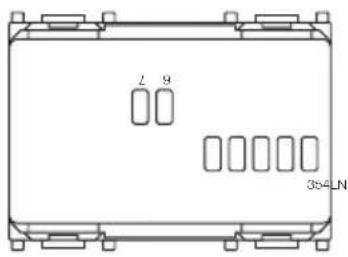
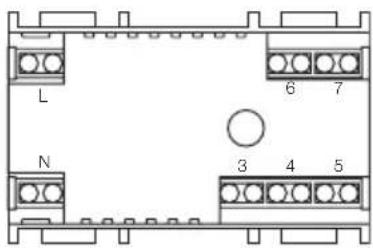
- terminals L - N: alimentazione 230 V~ ±10% 50-60 Hz
- morsetti 6 - 7: collegamento elettrovalvola VIMAR 16590 o elettrovalvola a riarmo manuale NO 12 V d.c. 13 W con energia di eccitazione non superiore a 0,4 Joule previa rimozione della resistenza di carico
- terminals 3 - 4 - 5: output relay with change-over contact for connection of extra alarm signals and for solenoid valves which differ from the one indicated above (terminals 3-4 if normally closed; terminals 4-5 if normally open)
All the solenoid valves must be of the manually resettable type.
If the solenoid valve or the load resistor connected to the terminals 6 and 7 are not of the above indicated type, the yellow LED of the detector will be flashes during normal operation to signal the lack of connection; this, however, does not impair the performance of the equipment.
It is possible to connect up more than one detector in the same building (different rooms), controlling one single solenoid valve. In this case, the voltage supply of each detector must be connected up to terminals L and N, respecting polarisation (L with L; N with N) and the outputs for the solenoid valve of each detector must be parallel connected, respecting the numbers on the terminals (6 with 6; 7 with 7).
In this way, a gas leak in any of the rooms will cause the gas supply to be interrupted, closing the solenoid valve, while the optical/acoustic warning on the detector responsible for the electronic switch-off pulse will indicate the room where the gas leak has taken place (see example figure 4).
NOTES
Idea: code 16591 - 16592
8000: code 08496 - 08497
Surface mounting units: code 01895 - 01896
The 230V power circuit, the 12 V DC solenoid valve output and the clean contact output relay are separated from each other by double insulation. This means that the relay can be connected to either a mains- or SELV-powered solenoid valve and that the 12 V DC solenoid valve output provides SELV power.
Surface mounting units: code 01895 - 01896
Surface mounting devices: at the end of the five years, its life may be extended to 10 years by replacing the internal sensor (VIMAR 01895.G sensor for Gas Stop GPL, and VIMAR 01896.M sensor for Gas Stop Metano). The sensor may be replaced no more than once and only by an expert technician.
Eikon: art. 20420 - 20421
Arke: art. 19420 - 19421
Plana: art. 14420 - 14421
The 230V power circuit and the 12 V DC solenoid valve output are separated from each other by double insulation. This means that the output provides SELV power.
The clean contact output relay is separated by a single insulation. This means that it can be connected to a mains-powered solenoid valve.
For the installer
Gas Stop GPL
art. 20421
art. 19421
art. 14421
Gas Stop Metano
art. 20420
art. 19420
art. 14420
Gas Stop GPL
art. 16591
art.08496
Gas Stop Metano
art. 16592
art.08497
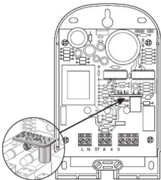
Gas Stop GPL - art. 01895
Gas Stop Metano - art. 01896
Examples of connections

VIMAR
Installation of one, single detector with VIMAR 16590 solenoid valve or equivalent
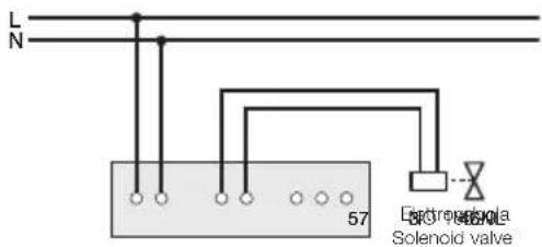
Fig. 3
Installation of more than one parallel detector with VIMAR 16590 solenoid valve or equivalent
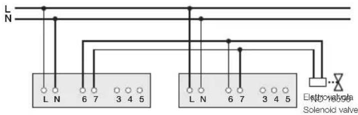
Fig. 4
For the installer
Installation of one, single detector with manually resettable solenoid valve NC 230 V~/12 V~/12 V d.c Idea, 8000, surface mounting devices) (NC-230 V~ Eikon, Arké, Plana)
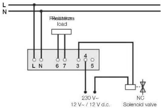
Fig. 5 Fig. 6
For the relay capacity, refer to the chapter "Technical data" on page 13.
Installation of one, single detector with manually resettable solenoid valve NO 230V / 12V / 12V d.c Idea,8000, surface mounting devices) (NO-230 V~ Eikon, Arké, Plana)
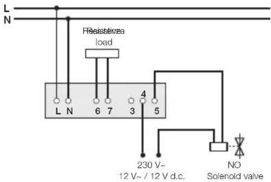
For the relay capacity, refer to the chapter "Technical data" on page 13.

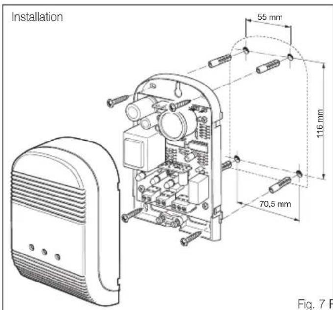
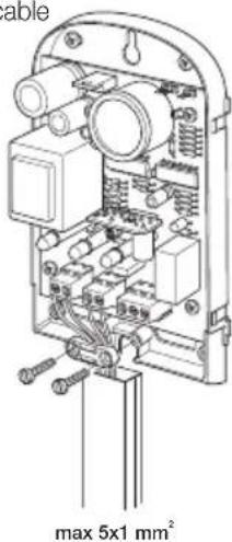
Surface mounting devices: sample installation and wiring
Fig. 7 Fig. 8
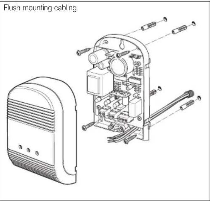
For the installer
Cabling with mini-trunking Cabling with cable
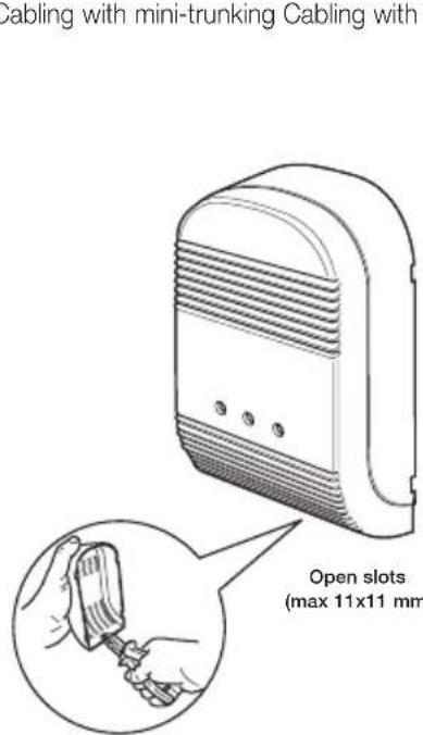
Only use the relay output with 230V a.c. load.
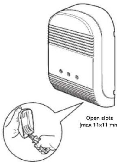
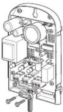
Fig. 10Fig. 9
m max 10mm H05VV-F 4x1 mm H05VV-F 5x1 mm

VIMAR
3. Installation and operating control
- Check that the plant is fitted with a gas cut-out solenoid valve and that it is correctly connected.
- Connect the 230V ± 10% 50-60 Hz voltage to the terminals L and N.
The detector runs an approx. 60 s timed PRE-HEATING cycle during which the solenoid valve and buzzer are inhibited: this cycle is indicated by both the green LED and yellow LED ON.
- Once the preheating cycle has terminated, the yellow LED turns off and the detector is operational.
- To test the device, hold the "VIMAR test gas" canister 01899 vertically with the valve uppermost and the nozzle against the detector's lower grille.
- Operate the single-dose calibrated nozzle to release the test gas: the detector will buzz, its red LED will turn ON and, after 20 seconds, it will close the solenoid valve with a repeated pulse signal every 15 s on terminals 6 and 7 while switching the output relay contact (terminals 3-4-5)
When the red LED goes out (end of the alarm state), the buzzer is switched off, the contact on terminals 3-4-5 is commuted and the pulses to terminals 6 and 7 cease.
If the operating check is successful, the gas supply will be switched on again by resetting the solenoid valve manually.
Notes
- For carrying out operational test, using exclusively the "Gas Test" cylinder delivered with detector. Do not use gas from lighters as it damages the internal sensor irreparably
-
Do not expose the device to:
-
solvent vapour
perfume vapour, bleach, ammonia, etc. - glue, colours and silicones vapours
- different gases from those prescribed
For the installer
4. Technical characteristics
Supply voltage: 230V ± 10% 50-60 Hz
- Sensor: stannic oxide semiconductor with physical filter
- Calibration: sealed with thermal compensation
Gas Stop GPL operating threshold: alarm: 9% L.I.E. (iso-butane)
Gas Stop Metano operating threshold: alarm: 9% L.I.E. (methane)
Electronic protection against short circuit without fuse
- Terminals L - N: supply voltage 230 V~ 50-60 Hz
- Terminals 6 - 7: connection VIMAR 16590 solenoid valve or manually resettable solenoid valve NO 12V d.c. 13W with maximum excitation of 0.4 Joule after removing the load resistor
- Terminals 3-4-5: clean change-over contact output relay for connecting additional alarms and solenoid valves of other types from that indicated above (terminals 3-4 for NC units, terminals 4-5 for NO units):
- NO 5 A 250 V~ (Eikon, Arké, Idea, Plana, 8000, surface mounting devices)
- NO 5 A 12 V DC (Idea, 8000, surface mounting devices)
- NO 10 A 12 V~ (Idea, 8000, surface mounting devices)
- NC 2 A 250 V~ (Idea, Plana, 8000, surface mounting devices)
- NC 3 A 12 V~ (Eikon, Arké, Idea, 8000, surface mounting devices)
- NC 1 A 12 V DC (Idea, 8000, surface mounting devices)
- Operating signals:
- acoustic, through piezoelectric buzzer 85 dB a 1 m
- optical, through frontal (green ① , yellow ▲ red)
- Useful life of the detector:
- Eikon, Arke, Idea Plana, 8000: 5 YEARS from the time of installation
- Surface devices: 10 YEARS from the time of installation by replacing the sensor after 5 YEARS
- Protection degree:
- IP40 for flush mounting devices (Eikon, Arké, Idea, Plana, 8000)
- IP42 for surface mounting devices
- Operating temperature: from -10^ to +40^
- Allowed relative humidity: 30-90% max without condensation
- Self-extinguishing, poly-carbonate enclosure
- Screw terminals for rigid or flexible conductors up to 2.5mm^2
5. Installation rules
Installation should be carried out by qualified personnel in compliance with the current regulations regarding the installation of electrical equipment in the country where the products are installed.
The power mains must be equipped with an omni-polar circuit breaker.
6. Conformity to laws and standards
- Flush mounting devices (Eikon, Arké, Idea, Plana, 8000):
LV Directive
-Standard CEI 216-8 - EMC Directive
-Standard EN 50270 - Surface mounting devices:
LV Directive - Standard EN 50194-1
EMC Directive
-Standard EN 50270

VIMAR
REACH (EU) Regulation no. 1907/2006 - Art.33. The product may contain traces of lead.
NOTE
THE INSTALLATION OF GAS DETECTORS DOES NOT RELIEVE THE USER OF THE OBLIGATION TO OBSERVE ALL RULES GOVERNING THE SPECIFICATION AND INSTALLATION OF GAS EQUIPMENT (EN 1775), VENTILATION OF INSTALLATION AREAS AND EXHAUSTING OF COMBUSTION PRODUCTS PRESERVED BY ESTABLISHED TECHNICAL STANDARDS AND LEGISLATION.

WEEE - Information for users
If the crossed-out bin symbol appears on the equipment or packaging, this means the product must not be included with other general waste at the end of its working life. The user must take the worn product to a sorted waste center, or return it to the retailer when purchasing a new one. Products for disposal can be consigned free of charge (without any new purchase obligation) to retailers with a sales area of at least 400m^2 if they measure less than 25cm . An efficient sorted waste collection for the environmentally friendly disposal of the used device, or its subsequent recycling, helps avoid the potential negative effects on the environment and people's health, and encourages the re-use and/or recycling of the construction materials.
For the user
ATTENTION
Your gas detector is a high technology product, design and manufactured in compliance with established technical standards and EC Directives.
The detector has a lifetime of 5 years from the time it is installed.
For surface detectors 01895 and 01896, the service life may be extended to 10 years by replacing the sensor after 5 years (VIMAR 01895.G sensor for Gas Stop GPL, VIMAR 01896.M sensor for Gas Stop Metano). The sensor may be replaced one time only and exclusively by a qualified technician (see page 2).
Carefully read the user instructions.
Make sure to contact your installer on the expiry date for compulsory replacement of the device.
The expiry date must be indicated on the device by the installer using the provided plate/label at the time of installation.
INSTALLATION NOTES
Apply to authorized technicians for all installation and any routine and non-routine maintenance operation as well as for the replacement of the detector at the end of its life-time.
1.Description
Gas Stop GPL and Gas Stop Metano
The LPG/methane electronic gas detectors are intended to detect the presence in a room of liquid and LPG gas (Gas Stop GPL) or methane (Gas Stop Metano), in concentrations far below the danger threshold, and to operate the solenoid valve to cut off gas delivery and issue a visual (LED) and acoustic (buzzer) warning.
The optical signals are located on the front of the equipment and indicate, according to their state (off flashing oron) the operating mode of the detector (as shown in the paragraph "Operations"). The alarm buzzer is inside the detector and sounds to indicate an alarm condition (see "Operation").
Calibration of the sensitivity of the specified value (see "Characteristics"), for each detector, is set and sealed at the factory, in a special gas chamber.
Each detector is supplied with a thermal compensation circuit, in its electronic card, which maintains sensitivity at the calibrated level even when ambient conditions (temperature, humidity) change.

VIMAR
2. External indications
Legend
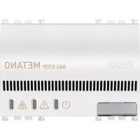
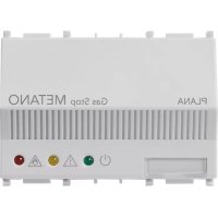
- Green LED: operating state of the detector
- Yellow LED : faulty sensor or disconnected solenoid valve
- Red LED: state of alarm
- Detector replacement date plate position
N.B. Refer to "Operations" paragraph for a more detailed explanation of the state of the optical signals
For the user
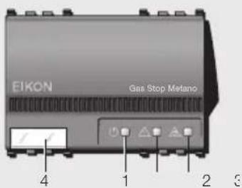
Gas Stop GPL - art. 20421
Gas Stop Metano - art. 20420
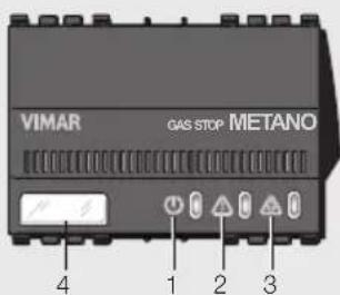
Gas Stop GPL - art. 19421
Gas Stop Metano - art. 19420
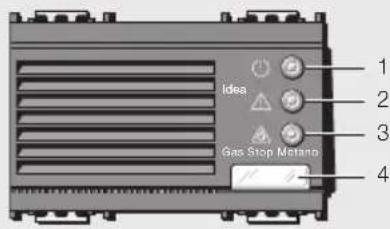
Gas Stop GPL - art. 16591
Gas Stop Metano - art. 16592
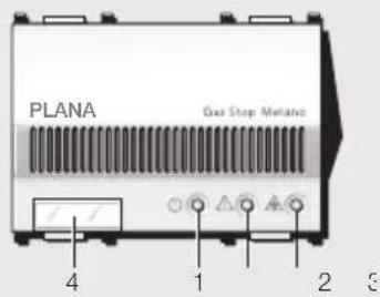
Gas Stop GPL - art. 14421
Gas Stop Metano - art. 14420
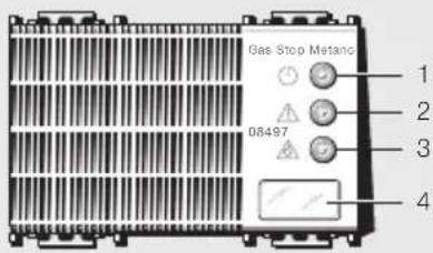
Gas Stop GPL - art. 08496
Gas Stop Metano - art. 08497
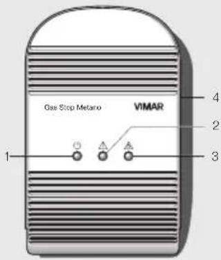
Gas Stop GPL
art.01895
Gas Stop Metano
art.01896
3. Operations
3.1 Starting up the detector

When it is switched on, the detector runs an approx. 60 s timed PRE-HEATING cycle during which the solenoid valve and buzzer are inhibited: this cycle is indicated by both the green LED and yellow LED ON.
3.2 Normal operations
Once the preheating cycle has terminated, the yellow LED turns off and the green LED stays on, to indicate that the detector is operational.


3.3 Alarm
Once danger threshold 1 has been exceeded (alarm) the red LED turns on, the buzzer sounds and, if the danger condition persists for more than 20s , the detector closes the solenoid valve and switches the relay.

The command is given by means of a pulse which is repeated every 15 seconds, sent to terminals 6 and 7 and by commutation of the output relay contact (terminals 3-4-5).
The pulse is indicated by the yellow LED (flashing during the pulse signal to the solenoid valve).
When the red LED goes out (end of the state of alarm), the buzzer is switched off, the contact on terminals 3-4-5 is commutated and the pulses to terminals 6 and 7 stop.
It is now necessary to reset the solenoid valve by hand in order to reinstate the normal gas supply.
For the user
4. Anomalies

4.1 Solenoid valve not connected
If the yellow LED flashes while the green LED 1 is on, this indicates that the solenoid valve or load resistor is not correctly connected to terminals 6 and 7.

4.2 Fault
If the detector's internal sensor malfunctions, the yellow LED turns on and stays on. Contact your installer to have it serviced.
5. Periodical checks
VIMAR recommends that the detector should be checked periodically using the "VIMAR test gas" cylinder supplied with the equipment. Proceed as follows:
- Hold the "VIMAR test gas" canister vertically with the valve uppermost and the nozzle against the detector's grille, then operate the single-dose calibrated nozzle once to release the test gas.
After a few seconds, the detector will activate the alarm buzzer, lighting up the red LED and closing the solenoid valve and output relay by means of a pulse signal repeated at 15 second intervals on the terminals 6 and 7 and by commutating the output relay contact (terminals 3-4-5).
When the red LED goes out (end of the alarm state) the buzzer will stop and the contact on terminals 3-4-5 will be switched off, stopping the pulses at terminals 6 and 7.
After successfully carrying out the operating check, turn on the gas supply again using the manual reset on the solenoid valve. Other test methods (e.g. lighters, other gases) can damage the sensor and/or result in incorrect indications.
6. How to behave in the event of a gas leak
CAUTION! In case of an alarm, keep calm and:
- Turn off all open flames and all gas appliances
- Close the tap on the gas meter or on the LPG cylinder
- Do not turn any lights on or off; do not switch on any electrical equipment or devices (compresi rivelatori di gas)
- Open doors and windows to increase ventilation
- Do not use the phone inside a building in which there is a suspected gas leak
If the alarm stops the cause must be found immediately and the necessary measures taken.
If the alarm continues and the cause of the gas leak cannot be found or eliminated, leave the building and notify the emergency services, once outside.

VIMAR
7.Warnings
- Do not tamper with or open the device: electric shock hazard, danger of damage to the detector.
- Clean the device only with a damp cloth. Keep the aeration grilles free of obstructions.
-
Do not expose the device to:
-
sprays
- cigarette lighter gas
- solvent vapour
perfume vapour, bleach, ammonia, etc. - glue, colours and silicones vapours
- other gases from that prescribed
- direct cooking vapours
-etc. - In order to warn of gas leaks, LPG and methane gases contain an odorous substance. This odour may be noticed before the detector operates, although the latter is calibrated to operate far below the gas explosion threshold.

VIMAR
FRANÇAIS - 1
ATTENTION!
1. Installation Gas Stop
1. Gas Stop Installation
If the alarm stops the cause must be found immediately and the necessary measures taken.
Kai yia n th eon oe Aetoupyia
ms ouakeun, aeneuuvtheir e
EouoOoTnHvoucTexVkoUc.
O aivxveunns ypaepiou n eBaviou
TpTeTVAeYkaHioTcTAtOEeON
EkeTeiEvn ot quoikn kukAoopopia
Tou aepa, oe anootn Tou 6ev
Urrpbaive 3-4 m afo Aebnre,
Bepootipwves, 0ties kai piae
Aiaβaote TpooeRTiKa tic oBnyie yia to xphotn.
ATTEUUVEITE OTOV EYKATAOTaTn aac kata Tny nuepounvia ANGC wote va apovtioe iia TNY avaykaia avtikataotaon TTs ouokeunc. H nuepounvia Anc TpETei va avaypapetai otn ouokeun atto tv EYkataotatn xpnoioutoiwvtaq TNY EIDIK TIVAKIDA/ETIKETA KA tN theo 0E AIToupyia.
Gas Stop LPG kai Gas Stop Me0cvio
Oi nAeKtpovikoi avxveutec uypaepiou kai eBaviou evai katalnoi yia tv avxveun Tng TAPOUAC EVA Xwpo LPG kai uypaepiou (Gas Stop GPL) n MeBaviou (Gas Stop Metano) eavuauynuykEvtpwn ToAU kATUepn aTo oApio ETIKVuvotnac kai yia vaETeuaivouv Otvn AekpbaBida on-off diakottovac mT Ntapoxn aeipouk EtnionlaivovTAC ME OTNIKEC EvdeieEIG (Auxvie) kai nxntkaOnata (BoBnTs) tv avxveun aepiou kai thdiakottin ts TAPOXN.
O Evdeikkeauxvie Bpiokovta otyn TPOoOHN ts ouakeunc kai avaloywue Me tvkataoan (0bnotn ,avaaupnn n avapuevn ) utobawouvnt kataoanaeaupyiaac tou avxveum (oumuwa me tvnapaypao "Aetoupyia). O BouBntnc yto npntko onma Bpoketar oTo eowtepiok tou avixveum kai ETTIOHuaivei tvkataoan ouvayepuo (BA. "Aetoupyia").
Hpuon Tou opou etepbaoc otny kaopioevn tni (BA. "Xapaknpiotká") npayatottoietai kai oppayicetai aTO epyootaoo eKaTALno Toaalmo ia KaBc avxveun, otnv

VIMAR
nAektpovikn Tlaketau Tou OTOIOU UTIAPXeI Kukawma ThepkiNc AVNTATBmNG Wote o BaHoc TNS EuaioBnoiaC vTAPaPeVEI TAVOTE Otaepoc avEapnta cto metaBoAn Tuv ouvKnWv Tou TEPiBaALovTOx XPnOg (Thepokpaia, uypaia).
2. Egewepikcs EvdeieEis
Yrrovnua
The sensor has a service life of 5 years from the time of installation; it can be replaced by qualified personnel one time only to extend the detector's life to 10 years. Before replacing the sensor, carefully read the label affixed to the detector and ensure that the sensor has NEVER been previously replaced, otherwise proceed to replace the entire device.
To replace the sensor, proceed as follows (see page 24).
ATTENTION!


- VIMAR
- CONTENTS
- For the installer
- Installation Gas Stop
- Connections
- All the solenoid valves must be of the manually resettable type.
- NOTES
- Surface mounting units: code 01895 - 01896
- Examples of connections
- Installation and operating control
- Technical characteristics
- Installation rules
- Conformity to laws and standards
- NOTE
- WEEE - Information for users
- For the user
- ATTENTION
- INSTALLATION NOTES
- 1.Description
- Gas Stop GPL and Gas Stop Metano
- External indications
- Legend
- Operations
- Starting up the detector
- Normal operations
- Alarm
- Anomalies
- Solenoid valve not connected
- Fault
- Periodical checks
- How to behave in the event of a gas leak
- 7.Warnings
- ATTENTION!
- Gas Stop Installation
- Gas Stop LPG kai Gas Stop Me0cvio
- Egewepikcs EvdeieEis
- Yrrovnua
Brand : Vimar
Model : 20421.B
Category : Detector