
HP20032 - Battery charger HP - Free user manual and instructions
Find the device manual for free HP20032 HP in PDF.

| Device type | Jump starter and battery charger for 12V/24V lead-acid batteries |
| Model | HP20032 |
| Input voltage | 230 V single-phase, 50/60 Hz |
| Charging voltage | 12 V / 24 V |
| Charging current | 25-55 A |
| Starting current | 300 A |
| Recommended battery capacity | 80-700 Ah |
| Dimensions (packaging) | 39 x 33 x 64 cm |
| Weight | 16 kg |
| Protection rating | IP20 (indoor only) |
| Main functions | Slow charge, fast charge, jump start |
| Safety | Input and output fuse, ground wire, thermal protection, polarity reversal lock |
| Maintenance | Contact a professional; replace fuses with identical models (80A or 100A) |
| Spare parts | Spare fuses included; rectifier bridge, thermal relay, switch |
| Included accessories | 2 wheels, 1 axle, 1 support foot, 3 screws, user manual |
| Warranty | 24 months |
Frequently Asked Questions - HP20032 HP
User questions about HP20032 HP
0 question about this device. Answer the ones you know or ask your own.
Ask a new question about this device
Download the instructions for your Battery charger in PDF format for free! Find your manual HP20032 - HP and take your electronic device back in hand. On this page are published all the documents necessary for the use of your device. HP20032 by HP.
USER MANUAL HP20032 HP
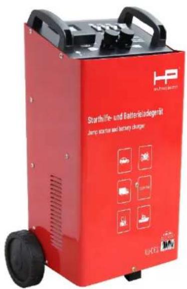
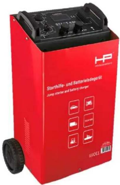
Starting aid and battery charger
Articles 20032 and 20075

AUTOZUBEHÖR
HP 20032
HP 20075
CONTENTS
ASSEMBLY SKETCH 02
ASSEMBLY METHODS 02
PRODUCT OVERVIEW 02
SPECIFICATIONS 03
NOTIFICATIONS 03
SAFETY REGULATIONS 04
OPERATION INSTRUCTIONS FOR CHARGER AND BATTERY ----04
WIRE CONNECTION 06
MAINTENANCE 07
DIAGRAM FOR CURRENT REGULATION 07
ELECTRIC DIAGRAM 08
TROUBLE SHOOTING 09
PACKING LIST 10
-
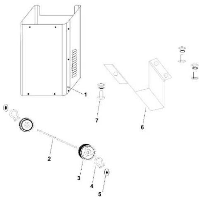
hole for the axle 2.axle
-
wheel
-
circlip for fixing the wheels
-
cover for the wheel hole
-
support 7.screw for the support
ASSEMBLING METHODS
-
Insert the axle (part 2) into the hole (part 1). Put the wheel (par 3) on the axle (part 2) and fasten it with the circlip (part 4). Fit the cover for the wheel hole (part 5).
-
Fasten the support to the bottom of the machine (part 6) with screw (part 7).
-
Please use the screw (part 9) to fit the handle (part 10) into the hole (part 8).
PRODUCTS OVERVIEW
This item has an auxiliary function for start-up, which can be used for charging and starting lead-acid batteries and batteries for motorcycles, automobiles, tractors and ships.
This item is installed with an input fuse and an output fuse, grounding wire connected to the power cable, making it safe and reliable.
◆ This item is installed with controlling switches for charging current and startup, adjustable current.
◆ Installed with two wheels and handle, enabling easy operation.
PRODUCT SPECIFICATION
| MODELITEM | HP 20032 HP 20075 | |
| Input voltage | 1PH 230V | 1PH 230V |
| Frequency | 50/60 HZ | 50/60 HZ |
| Charging Voltage | 12V/24V | 12V/24V |
| Charging Current | 25-55A | 20-90A |
| Starting Current | 300A | 500A |
| Reference Capacity | 80-700Ah | 100-1000Ah |
| Packing size(cm) | 39X33X64 | 42X33X75.5 |
| Weight | 16KG | 26KG |
NOTIFICATIONS
EN60335-2-29: Standards for charger

: Read the user's manual carefully before using.

de use only
IP20: Protection class
Imin: DC Min output current
Iboost: DC Max output current
START: Start current
SAFETY REGULATIONS
For the safety of persons and property, the following safety regulations must be observed when the charger is used.
-
As flammable gas can be generated while charging, the battery should be charged inside a well-ventilated room.
-
The protection class is IP20, the product must not be used outside when it is rainy or snowy.
-
The grounding wire must be connected to ensure the plug is properly earthed.
- Keep the charger level and right side up while charging,
- As the casing can generate heat during charging, it is prohibited to cover the vent of casing.
- The instructions for the battery and transportation tools should be strictly followed while charging.
- The battery should only be mounted or dismantled after the power is turned off.
- The maintenance work for the charger should be done by the professionals.
- A fuse and cable with the same specifications should be used when they need to be replaced.
- As sulfuric acid gas, hydrogen and oxygen, which are strongly corrosive, can be generated while charging, the battery should be charged inside a well-ventilated room. Flames and sparks should be kept away and smoking is prohibited.
- The power socket should be connected to the grounding wire to ensure the power cord is properly earthed.
- The battery should only be mounted or dismantled after the power is turned off.
- When electrified, the battery clamps should not be contacted with each other.
- The cover of battery should never be opened while charging.
- It is prohibited to connect the battery clamps the wrong way around.(e.g., never connect the red clamp of anode to the cathode of battery, or connect the black clamp of the cathode to the anode of battery)
- It is prohibited to use the charger for the charging of non-charging batteries.
- Only fuses of the same specification 80A or 100A, when replaced, may be used, otherwise the warranty will be void. A set of replacement fuses is supplied with each unit.
- In case the power cable is damaged, the damaged cable should be dismantled and replaced by professionals.
OPERATION INSTRUCTIONS FOR CHARGER AND BATTERY
To ensure that the charger and battery are used correctly and the machine is in good condition, the following rules must be followed:
-
Operation instructions for the battery
-
When battery does not have sufficient charge, its' terminal voltage remains the same, which means a 12V battery has the terminal voltage of 12V and a 24V battery has the terminal voltage of 24V. The main physical phenomenon indicating insufficient charge in the battery is the difference in specific gravity of the battery solution. Normally a battery has sufficient charge when the specific gravity of the battery solution is 1.28KG/L. If it is lower than 1.16KG/L, the battery is empty and won't have any electricity.
● The voltage of battery deviates from the normal value only when the battery is loaded or charged.
When loaded, the voltage is higher than its' usual value of terminal voltage.
If the battery is topped for some time (about 10-30 minutes) after it is loaded, and the terminal voltage is still lower than normal value, the battery may have quality defects.
- Remove the cover of the battery to see if there is sufficient electrolytic solution. If not, add distilled water.
-
As the electrolytic solution in the battery is dilute sulfuric acid and strongly corrosive, avoid contact with your skin or clothes. In case electrolytic solution was in contacted with your skin, wash the affected area with water immediately and seek medical attention.
-
Correct charging method
- It is possible to charge the batteries with the same capacities in parallel connection or when connected in series.
The terminal voltage of batteries in parallel connection or connected in series must match the output voltage of the charger.
It is recommended to charge the batteries when they are connected in series to ensure the current passing through each battery has the same value.
- Connecting the batteries: Connect the (red) anode of battery clamp to the anode of the battery and the corresponding terminal (12V or 24V) of the charger. Connect the (black) cathode of battery clamp to the cathode of the battery.
If a car battery needs to be charged, you should connect the charger to the terminal which is not connected with the chassis before. The connecting points must be far away from the battery and fuel tubes.
- Insert the power plug.
First turn the power switch to "ON" position, then turn the function switch "charge/start" to "charge" position. The ammeter will indicate a reading for the current (suitable for START-20, START-320, START-420). Adjust the current regulating switch to the suitable range for charging current (select the charging current according to DIN 41774 standards). START-520 and START-620 have an option for charging time.
For details, please refer to Section XII--Diagram for Current Regulating.
- While charging, the temperature of electrolytic solution in the battery should not exceed 45°C. If that temperature is reached before charging is completed, the charging current should be lowered to stop the increase in temperature.
- The following phenomena may occur after charging is finished: Specific gravity of battery solution is close to 1.28KG/L; Terminal voltage of battery is increased to more than 14V (or 28V); Electrolytic solution is bubbling heavily.
- After the charging is finished, the power should be turned off before the battery clamp is removed from the battery.
3. Auxiliary start
Note: Auxiliary start must be carried out strictly
Following the operation procedures specified for the product.
- Firstly use the charger to fast charge the battery for 10-15 minutes.
- Connect the pole of the charger to the engine's terminal not linked to the chassis, then connect the other pole to the engine's terminal which is linked to the chassis.
- Read the related instructions for the engine as provided by the manufacturer carefully.
- Insert the power plug, turn the power switch to "ON" position, then turn the function switch "charge/start" to "start" position. Now the engine can be started.
Attention: The start time is 3 seconds; the start for the second time should be 120 seconds later. Five times of cycled start are available.
If the engine is continuously started, 10 minutes of interval must be ensured between two start cycles so that the transformer inside the device can be cooled for restarting the engine.
WIRE CONNECTION
While charging a 12V storage battery, please connect the charging clamp (marked 1) to the middle connection (marked 12V).
While charging a 24V storage battery, please connect the charging clamp (marked 1) to the right connection (marked 24V).
MAINTENANCE
- Regular maintenance and repair work will ensure proper function and compliance with the safety requirements.
- Any improper or incorrect operation may cause failure and damage to the machine.
- The warranty period for the machine is one year commencing from the date of purchase. Within this time, users can take the machine with the invoice to the distributor or the designated department for repair.
- Before the maintenance work for machine is started, the operator must turn off the main power and the power switch of the machine.
- If the transformer is heating and no current is available from the transformer due to the over current while of charging, the over-heat protection device inside the charger was tripped to protect the transformer. In this case, the user should wait until the transformer is cooled before resuming the charging process.
DIAGRAM FOR CURRENT REGULATING
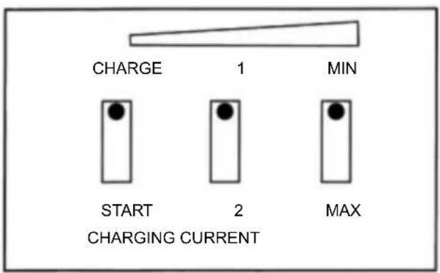
| POSITION SWITCH LACATION | |
| 1 CHARGE—MIN—1 | |
| 2 CHARGE—MIN—2 | |
| 3 CHARGE—MAX | |
| START START | |
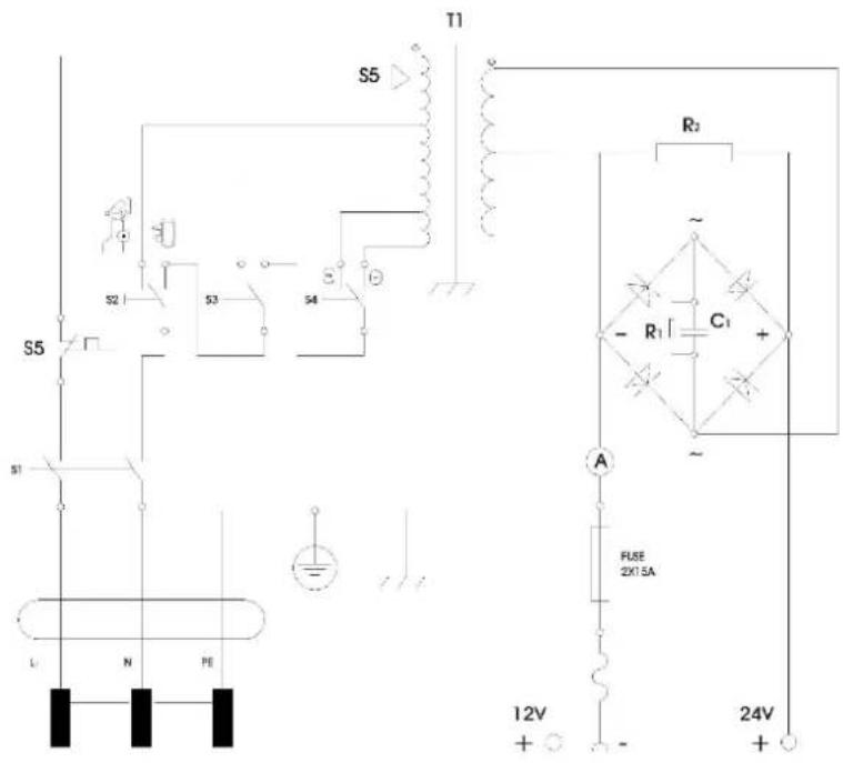
ELECTRIC DIAGRAM
TROUBLE SHOOTING
| Trouble Reason Shooting | |
| No output voltage 1.Fuse melted | 1. Replace with identical model fuse. |
| 2.Rectifier bridge burned | 2. Replace with identical model rectifier bridge. |
| 3.Temperature relay damaged | 3. Replace with identical model relay. |
| 4. Switch damaged | 4. Replace with identical model switch. |
PACKING LIST
| No | Name | Specification | Qty | Remark |
| 1 | Operating manual | 1pc | ||
| 2 Wheel | 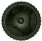 | 2pcs | ||
| 3 Circlip for fixing wheel |  | 2pcs | ||
| 4 Axle for wheel | 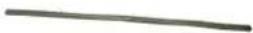 | 1pc | ||
| 5 Supporting foot | 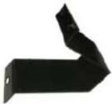 | 1pc | ||
| 6 | Screw for fixing supporting foot |  | 3sets | |
EC Declaration of Conformity

declare under their sole responsibility that the product
Starting aid and battery charger Articles 20032 and 20075
meets the essential protection requirements laid down in the European Directives
2014/35/EU (low voltage) 2014/30/EU (Electromagnetic Compatibility)
and its amendments are laid down.
The following harmonised standards have been adopted for conformity assessment is used:
EN 60335-1:2012+A11:2014+AC:2014, EN 60335-2-29:2004+A2:2010, EN 62233:2008+AC:2008, EN 55014-1:2006+A1:2009+A2:2011, EN 55014-2:2015, EN 61000-3-2:2014 EN 61000-3-3:2013
Bodenwerder, 02 October 2020

Claudia Pfefferkorn, Management
Disposal
please help to avoid waste.
Should you ever want to part with this article please bear in mind that many of its components are valuable raw materials and are recycled can.
Therefore, do not dispose of it in the dustbin, but lead it Please take it to your collection point for old electrical equipment.
Warranty conditions
This device is guaranteed for 24 months from the date of invoice in accordance with the legal provisions.
A copy of the invoice serves as proof of the warranty claim. Damage attributable to natural wear and tear, overloading or improper handling is excluded from the guarantee, as are wearing parts.
Complaints can only be accepted if the device is returned to the supplier unopened and carriage paid.

AUTOZUBEHÖR
Claudia Pfefferkorn, Direction
Élimination
- STARTING AID AND BATTERY CHARGER
- ARTICLES 20032 AND 20075
- ASSEMBLING METHODS
- PRODUCTS OVERVIEW
- PRODUCT SPECIFICATION
- NOTIFICATIONS
- SAFETY REGULATIONS
- OPERATION INSTRUCTIONS FOR CHARGER AND BATTERY
- AUXILIARY START
- WIRE CONNECTION
- MAINTENANCE
- DIAGRAM FOR CURRENT REGULATING
- ELECTRIC DIAGRAM
- TROUBLE SHOOTING
- PACKING LIST
- EC DECLARATION OF CONFORMITY
- DISPOSAL
- WARRANTY CONDITIONS
- ÉLIMINATION
Brand : HP
Model : HP20032
Category : Battery charger