ControlSpace WP22BD Dante - Wall socket BOSE - Free user manual and instructions
Find the device manual for free ControlSpace WP22BD Dante BOSE in PDF.

| Brand | Bose |
| Model | ControlSpace WP22BD Dante |
| Product Type | Network audio wall plate |
| Connectivity | Dante, Ethernet RJ45 |
| Power Supply | PoE (Power over Ethernet) |
| Dimensions (W x H x D) | 11.4 x 7.0 x 2.5 cm |
| Weight | 0.2 kg |
| Main Functions | Dante digital audio interface, high-quality audio transmission, integration into ControlSpace systems |
| Maintenance and Cleaning | Use a soft, dry cloth. Do not use abrasive products or solvents. |
| Safety | Installation by a professional only. Do not expose to moisture. Comply with local electrical standards. |
| Spare Parts and Repairability | No user-serviceable parts. Contact an authorized Bose service center. |
| General Information | Compliant with Class A (FCC/EN55022). Professional use in commercial environments. |
| Audio Resolution | Up to 24 bits / 96 kHz |
| Latency | Low (less than 1 ms) |
| Housing Material | Flame-retardant ABS plastic |
| Certifications | CE, FCC, RoHS |
| Warranty | 2 years (subject to conditions) |
Frequently Asked Questions - ControlSpace WP22BD Dante BOSE
User questions about ControlSpace WP22BD Dante BOSE
0 question about this device. Answer the ones you know or ask your own.
Ask a new question about this device
Download the instructions for your Wall socket in PDF format for free! Find your manual ControlSpace WP22BD Dante - BOSE and take your electronic device back in hand. On this page are published all the documents necessary for the use of your device. ControlSpace WP22BD Dante by BOSE.
USER MANUAL ControlSpace WP22BD Dante BOSE
natural_image
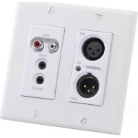
Front panel of a beige electronic device showing two DOSS ports (IN1 and IN2) with labeled pins, no readable text beyond port labels.ControlSpace® WP22B-D
2-in/2-out Dante™ Wall Plate
The symbols below are internationally accepted symbols that warn of potential hazards with electrical products.

This symbol, wherever it appears, alerts you to the presence of un-insulated dangerous voltage inside the enclosure – voltage that may be sufficient to constitute a risk of shock.

This symbol, wherever it appears, alerts you to important operating and maintenance instructions in the accompanying literature. Please read the manual.

WARNING: Use only with an agency approved power supply meeting all local and national regulatory requirements (ex. UL, CSA, VDE, CCC).
WARNING: This product is intended for installation by professional installers only! This document is intended to provide professional installers with basic installation and safety guidelines for this product in typical fixed-installation systems. Please read this document before attempting installation.
WARNING: Install in accordance with all local and national codes.

CAUTION: Only use a power supply that is a Limited Power Source (LPS) or a Class 2 power supply as defined in the IEC/UL 60950 safety standard.
CAUTION: If this equipment is powered from a PoE network, the network must not originate outside of the building or exit the building at any time.
- Read these instructions.
- Keep these instructions.
- Heed all warnings.
- Follow all instructions.
- Do not use this apparatus near water.
- Clean only with a dry cloth.
- Do not block any ventilation openings. Install in accordance with the manufacturer's instructions.
- Do not install near any heat sources such as radiators, heat registers, stoves, or other apparatus (including amplifiers) that produce heat.
- Do not defeat the safety purpose of the polarized or grounding-type plug. A polarized plug has two blades with one wider than the other. A grounding type plug has two blades and third grounding prong. The wider blade or the third prong is provided for your safety. If the provided plug does not fit into your outlet, consult an electrician for replacement of the obsolete outlet.
- Protect the power cord from being walked on or pinched particularly at plugs, convenience receptacles, and the point where they exit from the apparatus.
- Only use attachments/accessories specified by the manufacturer.
- Use only with the cart, stand, tripod, bracket, or table specified by the manufacturer, or sold with the apparatus.
- When a cart is used, use caution when moving the cart/apparatus combination to avoid injury from tip-over.
- Unplug this apparatus during lightning storms or when unused for long periods of time.
- Refer all servicing to qualified service personnel. Servicing is required when the apparatus has been damaged in any way, such as power-supply cord or plug is damaged, liquid has been spilled or objects have fallen into the apparatus, the apparatus has been exposed to rain or moisture, does not operate normally, or has been dropped.
pro.Bose.com Important Safety Instructions
-
When an external power supply is used to power this apparatus, that power supply shall be connected to a mains socket outlet with a protective earthing connection.
-
When permanently connected, an all-pole mains switch with a contact separation of at least 3mm in each pole shall be incorporated in the electrical installation of the building.
-
If rack mounting, provide adequate ventilation. Equipment may be located above or below this apparatus but some equipment (like large power amplifiers) may cause an unacceptable amount of hum or may generate too much heat and degrade the performance of this apparatus.

TO REDUCE THE RISK OF FIRE OR ELECTRIC SHOCK, DO NOT EXPOSE THIS APPARATUS TO RAIN OR MOISTURE.
Note: This equipment has been tested and found to comply with the limits for a Class A digital device, pursuant to Part 15 of the FCC Rules and EN55022. These limits are designed to provide reasonable protection against harmful interference when the equipment is operated in a commercial environment. This equipment generates, uses, and can radiate radio frequency energy and, if not installed and used in accordance with the instruction manual, may cause harmful interference to radio communications. Operation of this equipment in a residential area is likely to cause harmful interference, in which case the user will be required to correct the interference at their own expense.

This symbol means the product must not be discarded as household waste, and should be delivered to an appropriate collection facility for recycling. Proper disposal and recycling helps protect natural resources, human health and the environment. For more information on disposal and recycling of this product, Contact your local municipality, disposal service, or the shop where you bought this product.
Names and Contents of Toxic or Hazardous Substances or Elements
| Toxic or Hazardous Substances and Elements | ||||||
| Part Name | Lead (Pb) | Mercury (Hg) | Cadmium (Cd) | Hexavalent (CR(VI)) | Polybrominated Biphenyl (PBB) | Polybrominated diphenylether(PBDE) |
| PCBs | X 0 0 0 0 0 | |||||
| Metal parts | X 0 0 0 0 0 | |||||
| Plastic parts | 0 0 0 0 0 0 | |||||
| Speakers | X 0 0 0 0 0 | |||||
| Cables | X 0 0 0 0 0 | |||||
| 0: Indicates that this toxic or hazardous substance contained in all of the homogeneous materials for this part is below the limit requirement in SJ/T 11363-2006. | ||||||
| X: Indicates that this toxic or hazardous substance contained in at least one of the homogeneous materials used for this part is above the limit requirement in SJ/T 11363-2006. | ||||||
©2015 Bose Corporation. All rights reserved. All trademarks are the property of their respective owners.
The ControlSpace® WP22B-D Dante™ audio interface is a cost-effective multi-IO wall plate designed to fit into most dual-gang US junction boxes. Its size and I/O density make it easy to put Dante connectivity close to analog devices, helping to reduce costly and interference-prone analog wiring.
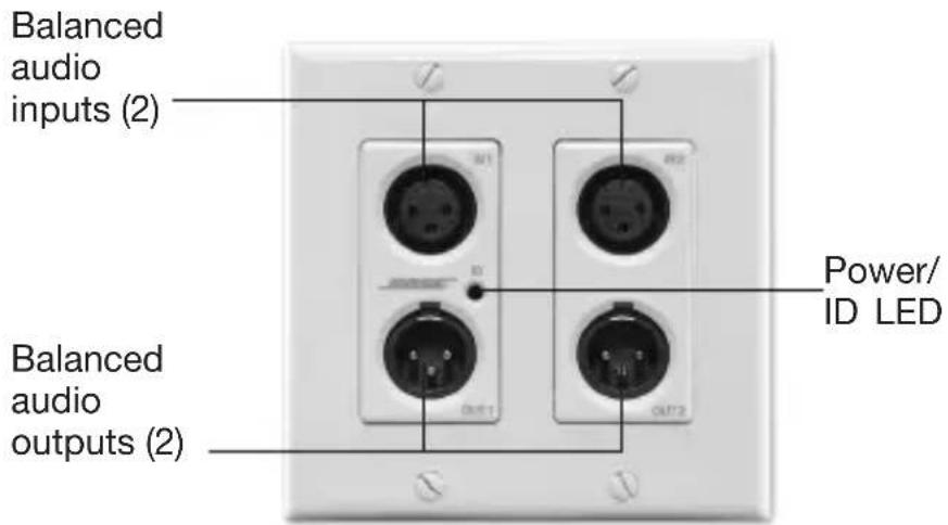
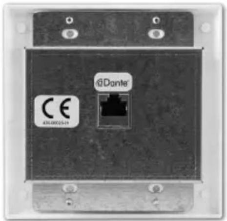
Figure 1. ControlSpace WP22B-D wall plate front and back
The WP22B-D includes two balanced mic/line XLR inputs and two balanced XLR line outputs; the inputs support 48V phantom power.
Connection to the Dante network is provided by a single Ethernet RJ-45 connector on the back of the unit. The WP22B-D is PoE powered over the network cable from a suitable PoE source (IEEE 802.3af) eliminating the need for a local power supply.
Note: The WP22B-D has a label on the front of the metal housing at the top that lists the last 6 digits of the MAC address. Important for initial device identification, these digits are part of the device's default network name when detected by Bose® ControlSpace® Designer™ software. The full MAC address is also given on the back of the unit.
What's in the Box
The WP22B-D comes supplied with the following:
- WP22B-D wall plate
- Mounting screws
- Decora plate
Mounting
A typical installation will involve mounting the wall plate into a 2-gang junction box or low-voltage ring. Before starting, make sure the wall box where the WP22B-D is to be installed is pre-wired with a suitable network cable back to a PoE enabled network switch or mid-span injector. If a mid-span injector is being used, the cable should be connected to the port that supplies both Ethernet and power (refer to the devices manual if unsure which port is which).
Attach the network cable from the switch/mid-span injector to the Dante network port of the Dante WP22B-D. If the switch or mid-span injector is already running and PoE is enabled, the unit should power up and the green ID LED on the front of the device should turn on.
With the cable attached, place the WP22B-D into the wall box taking care to not trap the cabling. Once in place, secure it with the mounting screws provided. Finally, fasten the Decora plate on top using the screws provided with it.
HARDWARE CONNECTIONS
The WP22B-D accepts and drives either unbalanced or balanced audio devices. Refer to the following diagrams and instructions for connecting different types of audio devices. Professional grade audio cabling is recommended to achieve the best audio performance throughout the system.
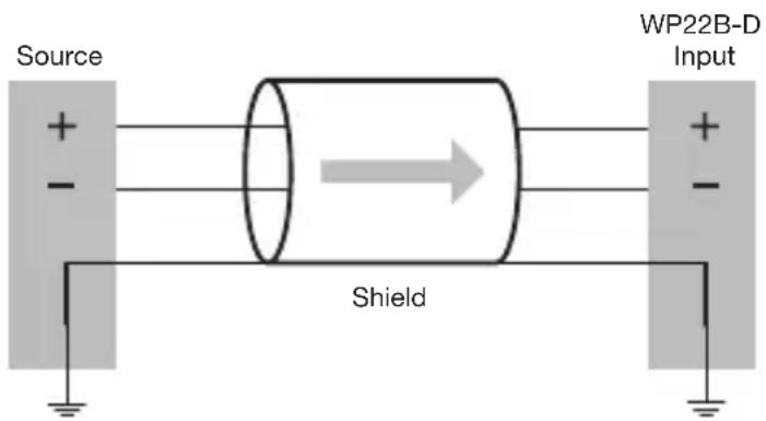
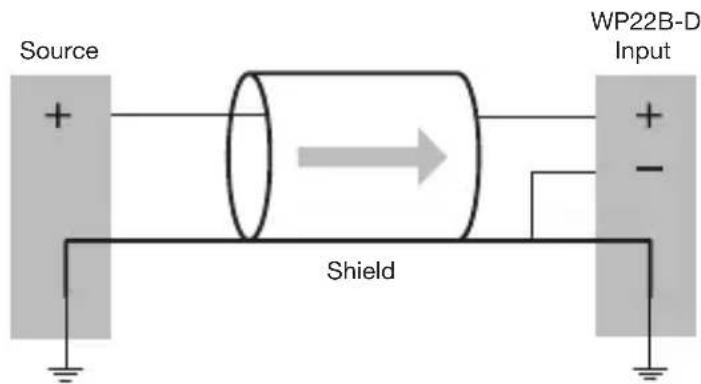
Input from a Balanced Source
To connect balanced sources to the WP22B-D, connect positive output to positive input, negative output to negative input, and connect the grounds together through the cable shield.
Figure 2.
Balanced source
connection
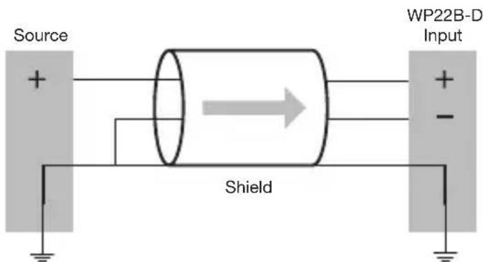
Input from an Unbalanced Source
To connect a 2-wire unbalanced source to the WP22B-D, connect the positive output of the unbalanced source to the positive input of the WP22B-D. Connect both the source and WP22B-D input grounds together, and short the negative input of the WP22B-D to ground at the input of the WP22B-D.
Figure 3.
2-wire unbalanced
source connection
To connect unbalanced sources with a 3-wire connection, short the negative conductor to the shield at the source connection.
Figure 4.
3-wire unbalanced
source connection
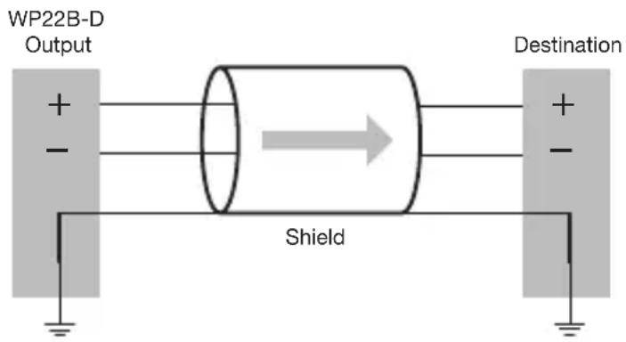
Output to a Balanced Destination
To connect to a balanced input on a destination device, connect the positive, negative and ground connections of both the WP22B-D output to the destination input respectively.
Figure 5.
Output to balanced
destination connection
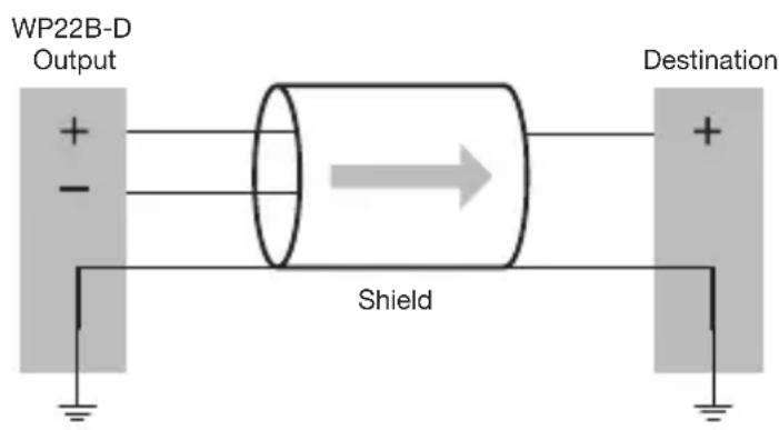
Output to an Unbalanced Destination
To connect the WP22B-D outputs to a 2-wire unbalanced input, connect the positive output to the destination's positive input and connect the grounds together through the cable shield. Leave the WP22B-D negative output floating.
Figure 6.
Output to unbalanced
destination connection
DEVICE CONFIGURATION
There are two parts of the device that require software to setup. First the audio routing, and second the configurable features of the device itself. Both should be carried out using ControlSpace® Designer™ software.
Dante ^™ is a trademark of Audinate Pty Ltd.
TECHNICAL SPECIFICATIONS
| Audio Inputs | |
| Input Channels Two (2) analog, balanced microphone/line level | |
| Connectors Two (2) XLR | |
| Phantom Power +48VDC, software selectable per input | |
| Gain Settings 0 / +25 / +40 dB, software selectable | |
| Input Impedance >1.8 kΩ at any gain setting | |
| Equivalent Input Noise -115 dBu (+40 dB gain) | |
| Maximum Input Level +12 dBu @ 0 dB gain | |
| Audio Outputs | |
| Output Channels Two (2) analog, balanced line level, with automatic muting on loss of Dante signal | |
| Connectors Two (2) XLR | |
| Output Gain 0 dB | |
| Output Noise < -90 dBu @ 0 dB gain | |
| Maximum Output Level +12 dBu | |
| Software Application | |
| ControlSpace® DesignerTM software v4.2 or later | |
| General | |
| A/D Converters 48 kHz, 24-bit | |
| System THD | < 0.01 % at any gain, input signal 3 dB below maximum |
| PoE Class Class 0 802.3af PoE PD compliant | |
| Certifications FCC Part 15 C | Class A, CE (EN 55022 Class A) |
| Dimensions | 2.75" H x 3.60" W x 1.88" D (70 mm x 91 mm x 48 mm) |
| Operating Temperature 32 °F | - 104 °F (0 °C - 40 °C) |
| Product Code 738677-0010 | |

BOSE® Better sound through research®
© 2015 Bose Corporation
The Mountain, Framingham, MA 01701-9168 USA
AM744551 Rev.00