RS560 - Diving regulator Tusa - Free user manual and instructions
Find the device manual for free RS560 Tusa in PDF.



| Product Type | Open circuit two-stage diving regulator |
| Brand | Tusa |
| Model | RS560 |
| First stage | R-500 (balanced piston) |
| Second stage | S-60 (grey) |
| Maximum depth | 50 m (164 ft) |
| Minimum water temperature | 10 °C (model limited to temperate waters) |
| Standards | EN250:2000, CE certified by RINA (notified body no. 0474) |
| Intermediate pressure | 9.5 bar (135 PSI) |
| First stage outlets | 4 low-pressure outlets, 2 high-pressure outlets |
| Housing material (2nd stage) | Super tough fiberglass reinforced nylon |
| Mouthpiece | High-density silicone |
| Supply | Compressed air only (no enriched oxygen) |
| Maintenance and cleaning | Rinse with fresh water (max 50°C) after each dive, annual inspection by an authorized center |
| Filter replacement | Every 100 dives or 1 year (by an authorized service) |
| Safety | Do not use in polluted water, do not breathe with short rapid breaths in cold water, open the valve slowly |
| Spare parts and repairability | Repair exclusively by a qualified TUSA service, use original parts |
| General information | Designed for sport diving, not for commercial or hookah use |
Frequently Asked Questions - RS560 Tusa
User questions about RS560 Tusa
0 question about this device. Answer the ones you know or ask your own.
Ask a new question about this device
Download the instructions for your Diving regulator in PDF format for free! Find your manual RS560 - Tusa and take your electronic device back in hand. On this page are published all the documents necessary for the use of your device. RS560 by Tusa.
USER MANUAL RS560 Tusa
RS-811, RS-812, RS-860
OWNER'S MANUAL
BEDIENUNGSANLEITUNG
MANUEL D'UTILISATEUR
HANDLEIDING
MANUAL DEL PROPIETARIO
LIBRETTO ISTRUZIONI
BEFORE USING ANY TUSA REGULATOR, READ THIS MANUAL COMPLETELY.
VOR GEBRAUCH EINES TUSA-ATEMREGLERS DURCHLESEN.
AVANT D'UTILISER UN DETENDEUR TUSA, VEUILLEZ LIRE CE MANUEL
COMPLETEMENT.
LEES DEZE HANDLEIDING VOLLEDIG VOOR U UW TUSA-ADEMAUTOMAAT GEBRUIKT.
SÍRVASE LEER COMPLETAMENTE ESTE MANUAL ANTES DE UTILIZAR.
text_image
Technical diagram of a mechanical assembly with numbered components for identificationR-300
| ITEM NO. | PART NO. | DESCRIPTION |
| 1 | R300-110 YOKE | KNOB |
| 2 | R300-090 YOKE | |
| 3 | 013 O-RING | |
| 4 | HO-50 RETAINING RING | |
| 5 | R300-120 FILTER | |
| 6 | TR-401-38 DUST COVER | |
| 7 | R300-130 YOKE RETAINER | |
| 8 | R300-080 WASHER,YOKE | |
| 9 | 011 O-RING | |
| 10 | R300-010 SPRING CONTROLLER | |
| 11 | R300-020 WASHER,SPRING | |
| 12 | R300-030 DIAPHRAGM SPRING | |
| 13 | R300-040 LOCK NUT | |
| 14 | R300-050 SPRING BASE | |
| 15 | R300-060 DIAPHRAGM | |
| 16 | R300-070 PROTECTOR | |
| 17 | R300-140 BODY | |
| 18 | R300-150 RETAINING CAP | |
| 19 | 014 O-RING | |
| 20 | R300-160 BACK-UP PLUG | |
| 21 | /R300-181 POPPET SEAT | |
| 22 | BR007 BACK-UP RING | |
| 23 | R300-190 BACK-UP SPRING | |
| 24 | 007-80 O-RING | |
| 25 | R300-260 HP POPPET BUTTON ASSY | |
| 26 | R300-221 ORIFICE | |
| 27 | R300-210 HP PLUG | |
| 28 | 012 O-RING | |
| 29 | R300-250 LP PLUG |
R-300DIN

text_image
Exploded view diagram of a mechanical assembly with numbered components for identificationR-300DIN
| ITEM NO. | PART NO. | DESCRIPTION |
| 1 /RSU215 DIN CAP | ||
| 2 R300-280 FILTER RETAINER | ||
| 3 B1 12A-90 O-RING | ||
| 4 S6 O-RING | ||
| 5 R300-290 FILTER | ||
| 6 /R300-271 NIPPLE,DIN ADAPTER | ||
| 7 R300-300 HANDWHEEL,DIN ADAPTER | ||
| 8 011 O-RING | ||
| 9 R300-050 SPRING BASE | ||
| 10 R300-060 DIAPHRAGM | ||
| 11 R300-260 HP POPPET BUTTON ASSY | ||
| 12 R300-140 BODY | ||
| 13 R300-221 ORIFICE | ||
| 14 /F300-181 POPPET SEAT | ||
| 15 R300-190 BACK UP SPRING | ||
| 16 R300-070 PROTECTOR | ||
| 17 R300-160 BACK UP PLUG | ||
| 18 BR007 BACK UP RING | ||
| 19 007-80 O-RING | ||
| 20 R300-150 RETAINING CAP | ||
| 21 014 O-RING | ||
| 22 R300-250 LP PLUG | ||
| 23 012 O-RING | ||
| 24 R300-210 HP PLUG | ||
| 25 R300-030 DIAPHRAGM SPRING | ||
| 26 R300-020 WASHER,SPRING | ||
| 27 R300-330 LOCK NUT | ||
| 28 R300-010 SPRING CONTROLLER | ||
| 29 R300-350 PISTON | ||
| 30 R300-340 END CAP | ||
| SPECIFICATIONS & PERFORMANCE DESCRIPTION | ||||
| WORKING PRESSURE: | 3360 PSI | 232 bar: (300 bar: R-300DIN only) | ||
| INTERMEDIATE PRESSURE: | 130-140 PSI | 9.5 - 10.0 bar | ||
| DIMENSIONS: | LENGTH: | 3.15 IN. | 80 MM | |
| ∅: | 1.89 IN. | 48 MM | ||
| WEIGHT:(w/o Hose) | 2.2 LBS. | 1000 GRAM | ||
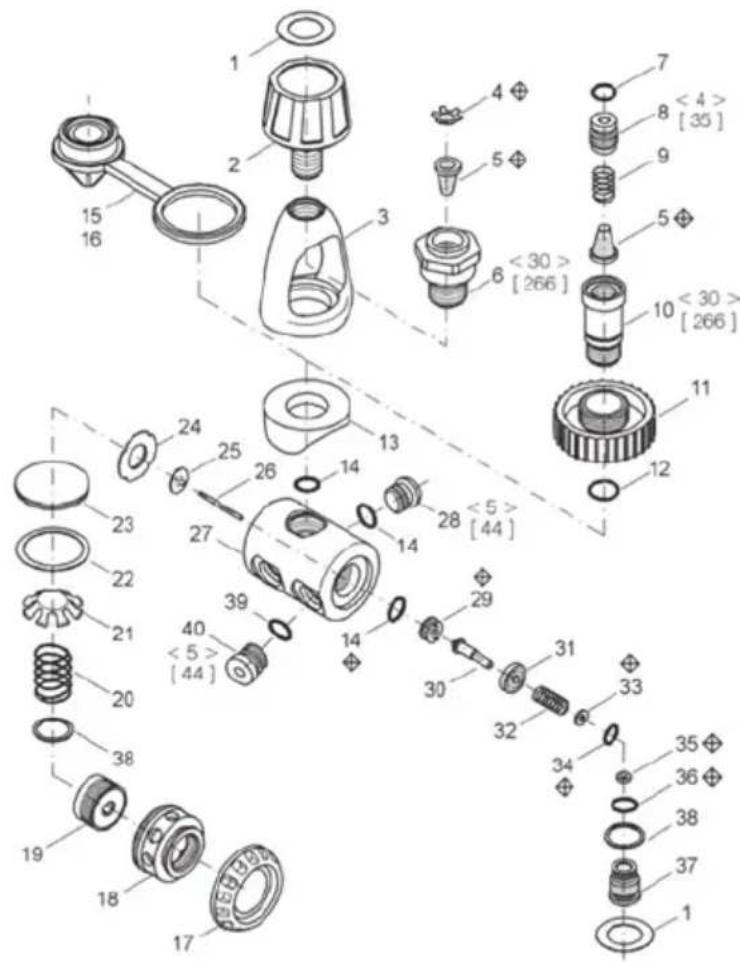
R-400, R-400DIN
text_image
<4> [35] 7 8 9 5 6 <30> [266] 10 <30> [266] 11 12 13 14 14 28 <5> [44] 29 30 31 32 33 34 35 36 38 37 38 39 40 <5> [44] 20 21 22 23 24 25 26 27 28 29 30 31 32 33 34 35 15 16 17 18 19R-400, R-400DIN
| ITEM NO. | PART NO. | DESCRIPTION |
| 5,7,8,9,10,11,12 | DIN-RS460 | DIN CONVERSION KIT |
| 1 R-400-010 DECAL | ||
| 2 R-400-020 YOKE SCREW 9/16" | ||
| 3 R-400-030 YOKE | ||
| 4 R-400-040 FILTER RETAINER | ||
| 5 R-400-050 FILTER | ||
| 6 R-400-060 YOKE RETAINER | ||
| 7 111 O-RING | ||
| 8 R-400-080 FILTER RETAINER 300 BAR | ||
| 9 R-400-090 SPRING | ||
| 10 R-400-100 DIN CONNECTOR 300 BAR | ||
| 11 R-100-110 DIN WHEEL 300 BAR | ||
| 12 014 O-RING | ||
| 13 R-400-130 SADDLE | ||
| 14 011 O-RING | ||
| 15 R-400-150 DUST CAP | ||
| 16 R-400-160 DUST CAP (DIN) | ||
| 17 R-400-170 PROTECTION CAP | ||
| 18 R-400-180 DIAPHRAGM NUT | ||
| 19 R-400-190 SPRING SCREW | ||
| 20 R-400-200 SPRING T.I.S. | ||
| 21 R-400-210 SPRING BASE | ||
| 22 R-400-220 DIAPHRAGM RING | ||
| 23 R-400-230 DIAPHRAGM | ||
| 24 R-400-240 DISC | ||
| 25 R-400-250 INSERT DISC | ||
| 26 R-400-260 DIAPHRAGM PIN | ||
| 27 R-400-270 BODY | ||
| 28 R-400-280 PLUG H.P. | ||
| 29 R-400-290 H.P. SEAT | ||
| 30 R-400-300 PISTON | ||
| 31 R-400-310 SLEEVE | ||
| 32 R-400-320 HP.S PRING | ||
| 33 R-400-330 WASHER | ||
| 34 006 O-RING | ||
| 35 R-400-350 BAL. CHAMBER HOLDER | ||
| 36 012 O-RING | ||
| 37 R-400-370 BAL. CHAMBER | ||
| 38 R-400-380 WASHER | ||
| 39 010 O-RING | ||
| 40 R-400-400 PLUG L.P. | ||
| 41 | ORIFICE | |
| 42 | H.P. SEAT COMPLETE | |
| 43 | O-RING |
| SPECIFICATIONS & PERFORMANCE DESCRIPTION | ||
| WORKING PRESSURE: | 3360 PSI | 232 bar: (300 bar: R-400DIN only) |
| INTERMEDIATE PRESSURE: | 130-140 PSI | 9.2 - 10 bar |
| DIMENSIONS: | LENGTH: | 5.30 IN. 135 MM |
| ∅: | 2.72 IN. 69 MM | |
| WEIGHT:(w/o Hose) | 1.87 LBS. 850 GRAM | |
R-500
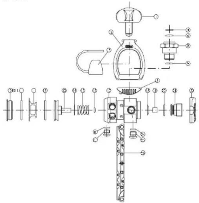
text_image
Technical diagram of a mechanical assembly with numbered components for identificationR-500DIN
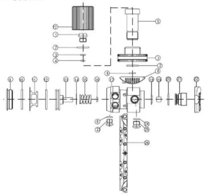
text_image
Exploded view diagram of a mechanical assembly with numbered components for identificationR-500
| ITEM NO. | PART NO. | DESCRIPTION |
| 1 | R300-110 | YOKE KNOB |
| 2 | /R500-040 | YOKE |
| 3 | HD-50 | RETAINING RING |
| 4 | R300-120 | FILTER |
| 5 | /R500-060 | YOKE RETAINER |
| 6 | 011 | O-RING |
| 7 | TR-401-38 | DUST COVER |
| 8 | /R500-110 | SADDLE |
| 9 | /R500-050 | LP CHAMBER PLUG |
| 10 | 024 | O-RING |
| 11 | /R500-030 | PISTON STOPPER |
| 12 | 020 | O-RING |
| 13 | /R500-020 | PISTON |
| 14 | /R500-090 | SPACER |
| 15 | /R500-130 | SPRING |
| 16 | 009 | O-RING |
| 17 | /R500-010 | BODY |
| 18 | /R500-140 | ADJ SPRING |
| 19 | /R500-080 | HP SEAT |
| 20 | 013 | O-RING |
| 21 | /R500-070 | HP SEAT PLUG |
| 22 | /R500-120 | CAP |
| 23 | R300-250 | LP PLUG |
| 24 | 012 | O-RING |
| 25 | R300-210 | HP PLUG |
| 26 | /R500-100 | BELT |
R-500DIN
| ITEM NO. | PART NO. | DESCRIPTION |
| 1 R300-280 | FILTER RETAINER | |
| 2 11 2A-90 | O-RING | |
| 3 S6 | O-RING | |
| 4 R300-290 | FILTER | |
| 5 R300-271 | NIPPLE,DIN ADAPTER | |
| 6 011 O-RING | ||
| 7 R300-300 | HANDWHEEL,DIN ADAPTER | |
| 8 /R50 0-110 | SADDLE | |
| 9 /R500-050 | LP CHAMBER PLUG | |
| 10 024 O-RING | ||
| 11 /R500-030 | PISTON STOPPER | |
| 12 020 O-RING | ||
| 13 /R500-020 | PISTON | |
| 14 /R500-090 | SPACER | |
| 15 /R500-130 | SPRING | |
| 16 009 O-RING | ||
| 17 /R500-010 | BODY | |
| 18 /R500-140 | ADJ SPRING | |
| 19 /R500-080 | HP SEAT | |
| 20 013 O-RING | ||
| 21 /R500-070 | HP SEAT PLUG | |
| 22 /R500-120 | CAP | |
| 23 F300-250 | LP PLUG | |
| 24 012 O-RING | ||
| 25 F300-210 | HP PLUG | |
| 26 /R500-100 | BELT | |
| 27 /RSU215 | DIN CAP |
| SPECIFICATIONS & PERFORMANCE DESCRIPTION | ||||
| WORKING PRESSURE: | 3360 PSI | 232 bar: (300 bar: R-500DIN only) | ||
| INTERMEDIATE PRESSURE:......130-140 PSI | 9.2 - 10 bar | |||
| DIMENSIONS: | LENGTH: | 2.48 IN. 62.9 MM | ||
| ∅: | 1.68 IN. | 41 MM | ||
| WEIGHT:(w/o Hose) | 1.543 LBS. | 700 GRAM | ||
R-600
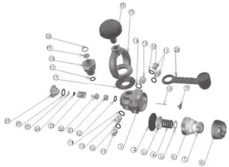
text_image
Exploded view diagram of a mechanical assembly with numbered parts for identificationR-600
| ITEM NO. | PART NO. | DESCRIPTION |
| 1 /R600-010 BODY | ||
| 2 R300-060 DIAPHRAGM | ||
| 3 R300-050 SPRING BASE | ||
| 4 R300-030 DIAPHRAGM SPRING | ||
| 5 R300-020 WASHER SPRING | ||
| 6 /R600-020 LOCK NUT | ||
| 7 /R600-030 CONTROLLER | ||
| 8 /R600-070 CAP | ||
| 9 /R600-040 BUTTON | ||
| 10 /R600-050 BOB PIN | ||
| 11 R300-250 LP PLUG | ||
| 12 011 O-RING | ||
| 13 F300-210 HP PLUG | ||
| 14 012 O-RING | ||
| 15 /R500-040 YOKE | ||
| 16 /R300-111 YOKE KNOB | ||
| 17 /R600-080 SADDLE | ||
| 18 /R500-060 YOKE RETAINER | ||
| 19 /R300-120 FILTER | ||
| 20 HO-50 RETAINING RING | ||
| 21 F300-221 ORIFICE | ||
| 22 /R300-181 POPPET SEAT | ||
| 23 F300-190 BACK-UP SPRING | ||
| 24 007-80 O-RING | ||
| 25 /SBR007 BACK-UP RING | ||
| 26 014 O-RING | ||
| 27 /R600-061 BLC PLUG | ||
| 28 TR-401-38 DUST COVER | ||
R-600DIN
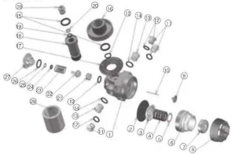
text_image
Exploded view diagram of a mechanical assembly with numbered parts for identificationR-600DIN
| ITEM NO. | PART NO. | DESCRIPTION |
| 1 /R600-010 BODY | ||
| 2 R300-060 DIAPHRAGM | ||
| 3 R300-050 SPRING BASE | ||
| 4 R300-030 DIAPHRAGM SPRING | ||
| 5 R300-020 WASHER SPRING | ||
| 6 /R600-020 LOCK NUT | ||
| 7 /R600-030 CONTROLLER | ||
| 8 /R600-070 CAP | ||
| 9 /R600-040 BUTTON | ||
| 10 /R600-050 BOB PIN | ||
| 11 R300-250 LP PLUG | ||
| 12 011 O-RING | ||
| 13 R300-210 HP PLUG | ||
| 14 012 O-RING | ||
| 15 112 A-90 O-RING | ||
| 16 R300-300 HANDWHEEL,DIN ADAPTER | ||
| 17 /R600-080 SADDLE | ||
| 18 /R300-271 NIPPLE DIN ADAPTER | ||
| 19 S6 C-RING | ||
| 20 R300-290 FILTER | ||
| 21 R300-221 ORIFICE | ||
| 22 /R300-181 POPPET SEAT | ||
| 23 R300-190 BACK-UP SPRING | ||
| 24 007-80 O-RING | ||
| 25 /$BR007 BACK-UP RING | ||
| 26 014 O-RING | ||
| 27 /R600-061 BLC PLUG | ||
| 28 R300-280 FILTER RETAINER | ||
| 29 /RSU215 PROTECTIVE CAP | ||
SPECIFICATIONS & PERFORMANCE DESCRIPTION
| WORKING PRESSURE: | 3360 PSI | 232 bar: (300 bar: R-600DIN only) | |||
| INTERMEDIATE PRESSURE: | 130-140 PSI | 9.2 - 10 bar | |||
| DIMENSIONS: | LENGTH: | 2.48 | IN. | 62.9 | MM |
| ∅: | 1.61 | IN. | 41 | MM | |
| WEIGHT:(w/o Hose) | 1.543 | LBS. | 640 | GRAM | |
R-700, R-700DIN
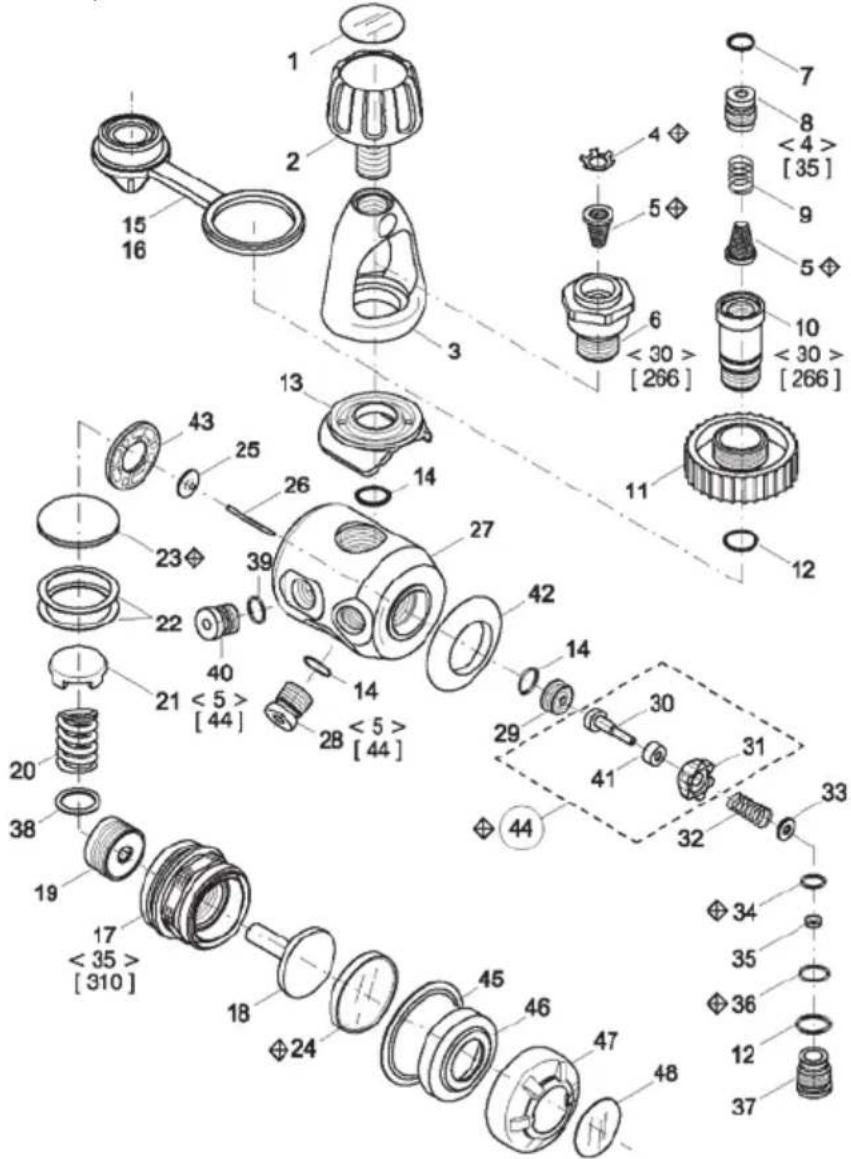
text_image
Exploded view diagram of a mechanical assembly with numbered parts and dimension annotationsR-700, R-700DIN
| ITEM NO. | PART NO. DESCRIPTION |
| 1 /R700-010 DECAL | |
| 2 /R700-020 YOKE SCREW | |
| 3 /R700-030 YOKE | |
| 4 /R400-040 RETAINER | |
| 5 /R400-050 FILTER | |
| 6 /R400-060 YOKE RETAIN | |
| 7 /11-PUR85 O-RING | |
| 8 | /R700-040 FILTER RET. 200 bar |
| /R400-080 FILTER RET. 300 bar | |
| 9 /R400-090 SPRING | |
| 10 | /R700-050 KNOB RET. 200 bar |
| /R400-100 KNOB RET. 300 bar | |
| 11 | /R700-060 KNOB. 200 bar |
| /R400-110 KNOB. 300 bar | |
| 12 /014-EP85 O-RING | |
| 13 /R700-070 SADDLE | |
| 14 /011-90 O-RING | |
| 15 /R400-150 INLET PROTECT. INT | |
| 16 /R400-160 INLET PROTECT. DIN | |
| 17 /R700-080 CHAMBER AF | |
| 18 /R700-090 LOAD TRANSMITTER | |
| 19 /R400-190 SPRING SCREW | |
| 20 /R400-200 SPRING T.I.S. | |
| 21 /R700-100 DIAPHR. DISC | |
| 22 /R400-220 DIAPHR. RING | |
| 23 /R700-110 DIAPHRAGM | |
| 24 /R700-120 DIAPHRAGM. AF | |
| 25 /R400-250 DISC. MET. | |
| 26 /R400-260 DIAPHR. PIN | |
| 27 /R700-130 BODY | |
| 28 /R400-280 PLUG H.P. | |
| 29 /R700-140 ORIFICE | |
| 30 /R700-150 H.P. VALVE | |
| 31 /R700-160 SLEEVE | |
| 32 /R400-320 SPRING | |
| 33 /R400-330 WASHER CENTRING | |
| 34 /R700-170 O-RING | |
| 35 /R400-350 RING | |
| 36 /012-EP85 O-RING | |
| 37 /R700-180 BAL. CHAMBER | |
| 38 /R700-190 WASHER | |
| 39 /010-EP O-RING | |
| 40 /R400-400 PLUG L.P. | |
| 41 /R700-200 CUP | |
| 42 /R700-210 BUMPER | |
| 43 /R400-240 DISC | |
| 44 /R700-220 HP VALVE COMPL | |
| 45 /R700-230 WASHER | |
| 46 /R700-240 DIAPH. RET. AF | |
| 47 /R700-250 BUMPER AF | |
| 48 /R700-260 DECAL | |
| SPECIFICATIONS & PERFORMANCE DESCRIPTION | |||||
| WORKING PRESSURE: 3360 PSI 232 bar: (300 bar: R-700DIN only) | |||||
| INTERMEDIATE PRESSURE: | 130-140 PSI | 9.2 - 10 bar | |||
| DIMENSIONS: | LENGTH: | 5.30 | IN. | 135 | MM |
| ∅: | 2.72 | IN. | 69 | MM | |
| WEIGHT:(w/o Hose) | 1.87 | LBS. | 850 | GRAM | |
R-800, R-800DIN
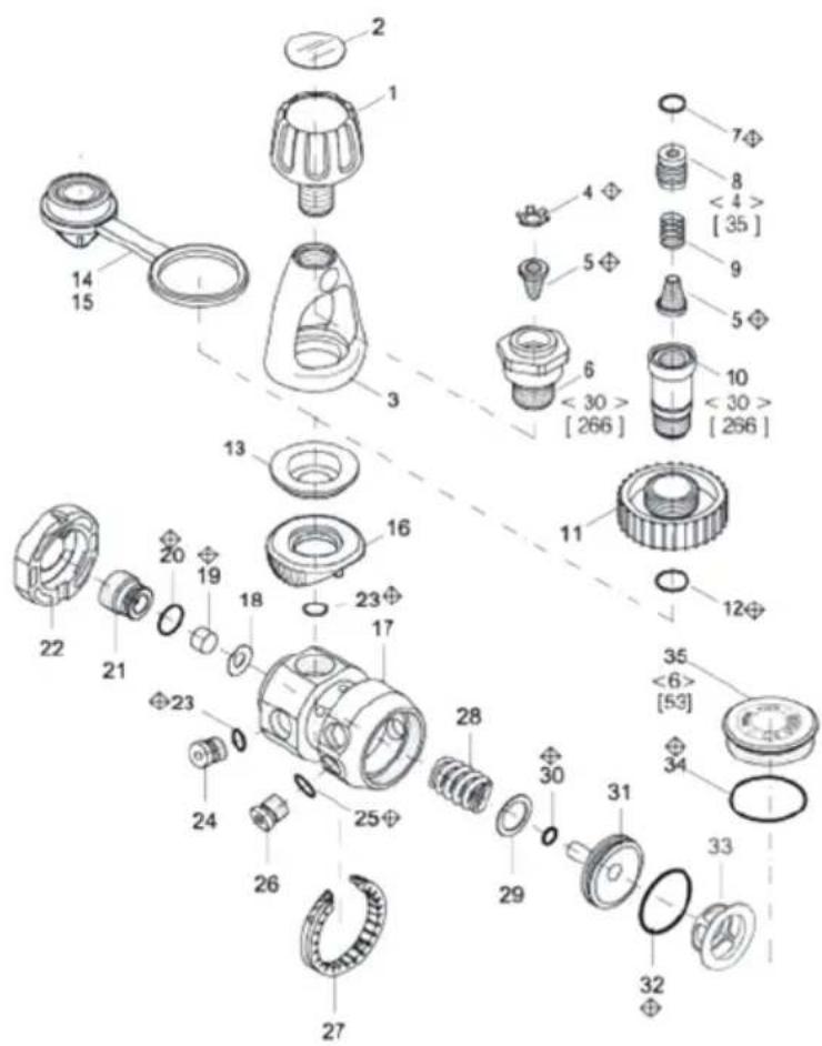
text_image
Exploded view diagram of a mechanical assembly with numbered parts and dimension annotationsR-800, R-800DIN
| ITEM NO. | PART NO. | DESCRIPTION | |
| R-800 R-800DIN | |||
| 1 /R700-020 YOKE SCREW | |||
| 2 /R800-010 DECAL | |||
| 3 /R700-030 YOKE 9/16" | |||
| 4 /R400-040 RETAINER | |||
| 5 /R400-050 /R400-050 FILTER | |||
| 6 /R400-060 YOKE RETAIN | |||
| 7 /111-PUR85 O-RING | |||
| 8 /R400-080 FILTER RET.300bar | |||
| 9 /R400-090 SPRING | |||
| 10 /R400-100 KNOB RET.300Bbar | |||
| 11 /R400-110 KNOB.300bar | |||
| 12 /014-EP85 O-RING | |||
| 13 /R800-020 /R800-020 WASHER | |||
| 14 | /R400-150 | /R400-150 | INLET PROTECT.INT |
| 15 | /R400-160 | /R400-160 | INLET PROTECT.DIN |
| 16 /R800-030 /R800-030 SADDLE | |||
| 17 /R800-040 /R800-040 BODY | |||
| 18 | /R500-140 | /R500-140 | ADJ SPRING |
| 19 /R500-080 /R500-080 HP SEAT | |||
| 20 | 013 | 013 | O-RING |
| 21 | /R800-060 /R800-060 HP | SEAT PLUG | |
| 22 | /R500-120 | /R500-120 | CAP |
| 23 | /011-90 | /011-90 | O-RING |
| 24 | /R400-280 /R400-280 HP | PLUG | |
| 25 | /010-EP | /010-EP | O-RING |
| 26 | /R400-400 /R400-400 LP | PLUG | |
| 27 | /R500-100 /R500-100 BELT | ||
| 28 | /R800-070 /R800-070 SPRING | ||
| 29 | /R800-080 /R800-080 WASHER | ||
| 30 | 009 | 009 | O-RING |
| 31 | /R800-090 | /R800-090 | PISTON |
| 32 | 020 | 020 | O-RING |
| 33 | /R500-030 | /R500-030 | PISTON STOPPER |
| 34 | 024 | 024 | O-RING |
| 35 | /R800-050 | /R800-050 | LP CHAMBER PLUG |
| SPECIFICATIONS & PERFORMANCE DESCRIPTION | |||||
| WORKING PRESSURE: | 3360 PSI | 232 bar: (300 bar: R-800DIN only) | |||
| INTERMEDIATE PRESSURE: | 130-140 PSI | 9.2 - 10 bar | |||
| DIMENSIONS: | LENGTH: | 2.48 | IN. | 62.9 | MM |
| ∅: | 1.61 | IN. | 41 | MM | |
| WEIGHT:(w/o Hose) | 1.543 | LBS. | 700 | GRAM | |
S-11 / SS-11
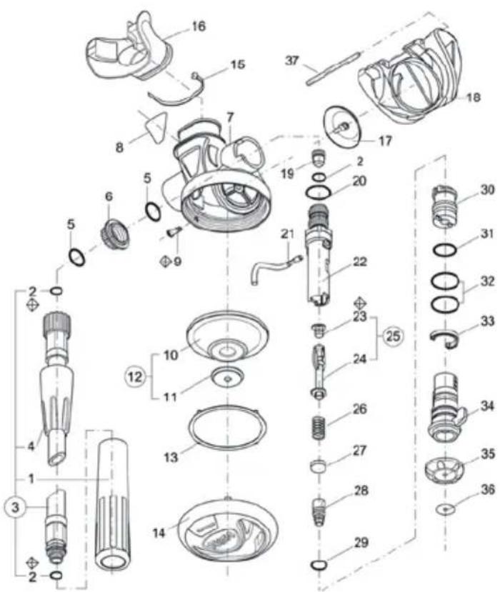
text_image
Exploded view diagram of a cleaning or repair device with numbered parts for identificationS-11 / SS-11
| ITEM NO. | PART NO. DESCRIPTION | |
| 1 TR-402-372 PROTECTIVE SLEEVE | ||
| 2 010 O-RING | ||
| 3 S-11-010 L.P. HOSE | ||
| 3 S-11-240 L.P. HOSE (SS-11) | ||
| 4 S-11-020 SLEEVE HOSE | ||
| 5 014 O-RING | ||
| 6 S-11-030 NUT. JAM | ||
| 7 S-11-040 CASE | ||
| 8 S-11-050 DECAL | ||
| 9 S-60-040 PIN | ||
| 10 | S-60-060 | DIAPHRAGM |
| 11 | S-60-070 | DISC |
| 12 | S-60-080 | DIAPHRAGM ASSY |
| 13 | S-60-090 | RING |
| 14 | S-11-100 COVER | |
| 14 | S-11-100Y | COVER (SS-11) |
| 15 | S-60-120 CLIP | |
| 16 RSU250 MOUTHPIECE | ||
| 17 | S-60-080 | EXHAUST VALVE |
| 18 S-11-110 EXHAUST TEE | ||
| 19 | S-60-050 | ORIFICE |
| 20 | 016 O-RING | |
| 21 | S-11-120 LEVER | |
| 22 | S-11-130 HOUSING | |
| 23 | S-11-140 SEAT | |
| 24 | S-11-150 POPPET | |
| 25 | S-11-160 POPPET ASSY | |
| 26 | S-60-270 SPRING | |
| 27 | S-11-170 SPRING HOLDER | |
| 28 | S-11-180 SCREW ADJ. | |
| 29 | 008 | O-RING |
| 30 | S-11-190 SLEEVE | |
| 31 | 903 | O-RING |
| 32 | 017 O-RING | |
| 33 | S-11-200 CLIP | |
| 34 | S-11-210 FLOW DEFLECTOR | |
| 35 | S-11-220 PLUG | |
| 36 | S-11-230 DECAL | |
| 37 | S-60-100 | PIN |
| SPECIFICATIONS | |||||
| DIMENSIONS: | Height: | 2.48 | IN. | 63 | MM |
| Length: | 4.25 | IN. | 108 | MM | |
| Width: | 4.17 | IN. | 106 | MM | |
| WEIGHT:(incl. Hose) | 0.749 | LBS. | 340 | GRAM | |
| HOSE: | Length: | 30/39 | IN. | 76/99 | CM |
S-12
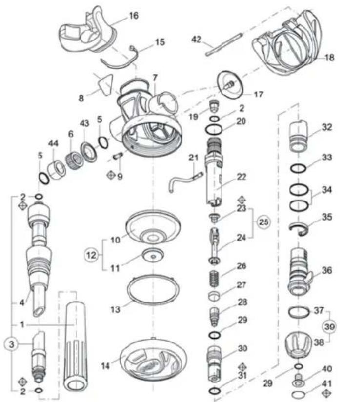
text_image
Exploded view diagram of a washing machine with numbered parts for identificationS-30
| ITEM NO. | PART NO. DESCRIPTION | |
| 1 TR-402-372 PROTECTIVE SLEEVE | ||
| 2 010 O-RING | ||
| 3 S-12-010 L.P. HOSE cm.75 | ||
| 4 S-12-020 SLEEVE HOSE | ||
| 5 014 O-RING | ||
| 6 S-12-030 NUT. JAM | ||
| 7 S-11-040 CASE | ||
| 8 S-12-040 DECAL | ||
| 9 S-60-040 PIN | ||
| 10 | S-11-06 0 DIAPHRAGM | |
| 11 S-11-070 DISC | ||
| 12 | S-11-080 | DIAPHRAGM ASSY |
| 13 | S-11-090 RING | |
| 14 S-11-100 PARGE ASSY | ||
| 15 | S-60-120 CLIP | |
| 16 RSU250 MOUTHP ECE | ||
| 17 | S-60-080 EXHAUST VALVE | |
| 18 S-11-110 EXHAUST TEE | ||
| 19 | S-60-050 ORIFICE | |
| 20 | 016 O-RING | |
| 21 | S-11-120 LEVER | |
| 22 | S-11-130 | HOUSING |
| 23 | S-11-140 | SEAT |
| 24 | S-11-150 | POPPET |
| 25 | S-11-160 | POPPET ASSY |
| 26 | S-60-270 SPRING | |
| 27 | S-11-170 | SPRING HOLDER |
| 28 | S-11-180 | SCREW ADJ. |
| 29 | 008 | O-RING |
| 30 | S-12-050 ADJ. SHAFT | |
| 31 | 902 | O-RING |
| 32 | S-12-060 SLEEVE | |
| 33 | 903 | O-RING |
| 34 | 017-EP | O-RING |
| 35 | S-11-200 CLIP | |
| 36 | S-11-210 | FLOW DEFLECTOR |
| 37 | S-12-070 RING | |
| 38 | S-12-080 KNOB | |
| 39 | S-12-090 KNOB ASSY | |
| 40 | S-12-100 SCREW | |
| 41 S-12-110 DECAL KNOB | ||
| 42 | S-60-100 PIN | |
| 43 | S-12-120 RING | |
| 44 | S-12-130 NUT. JAM SLEEVE | |
| SPECIFICATIONS | |||||
| DIMENSIONS: | Height: | 2.48 | IN. | 63 | MM |
| Length: | 4.25 | IN. | 108 | MM | |
| Width: | 4.72 | IN. | 120 | MM | |
| WEIGHT:(incl. Hose) | 0.793 | LBS. | 360 | GRAM | |
| HOSE: | Length: | 30/39 | IN. | 76/99 | CM |
S-20 / SS-20
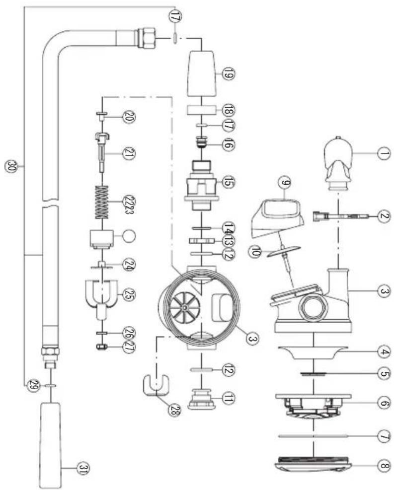
text_image
Technical diagram of a mechanical device with numbered components for identification and assembly reference.S-20 / SS-20
| ITEM NO. | PART NO. DESCRIPTION | |
| 1 | S40-010,/RSU 196 | MOUTHPIECE |
| 2 RSU116 MOUTHPIECE CLIP | ||
| 3 S10-111 CASE | ||
| 4 S50-050 DIAPHRAGM | ||
| 5 S50-040 DIAPHRAGM DISC | ||
| 6 /S20-110 DIAPHRAGM COVER | ||
| 7 034 O-RING | ||
| 8 /S20-120 DIAPHRAGM RETAINER | ||
| 9 S30-011 EXHAUST TEE | ||
| 10 S30-271 EXHAUST VALVE | ||
| 11 /S20-100 PLUG | ||
| 12 017 O-RING | ||
| 13 S30-250 SPACER | ||
| 14 S14 O-RING | ||
| 15 | /S20-010 DEMAND HOUSING | |
| 16 S30-040 ORIFICE | ||
| 17 010 O-RING | ||
| 18 | /S40-021 NUT RING | |
| 19 S30-030 SLEEVE | ||
| 20 | /S50-191 DEMAND SEAT | |
| 21 | /S20-060 DEMAND STEM | |
| 22 S50-160 DEMAND SPRING | ||
| 23 | /S20-030 DEMAND HOUSING CAP | |
| 24 | /S20-040 DEMAND STEM GUIDE | |
| 25 | /S20-050 DEMAND LEVER | |
| 26 | ST-003-92 WASHER | |
| 27 | ST-003-02 LOCK NUT | |
| 28 | /S20-090 WEDGE | |
| 29 OR106 O-RING | ||
| 30 | LPU067 / LPU151 | L.P.HOSE(L=30")ASSY |
| 31 TR-402-371 HOSE COVER | ||
| SPECIFICATIONS | |||||
| DIMENSIONS: | Height: | 2.91 | IN. | 74 | MM |
| Length: | 4.05 | IN. | 103 | MM | |
| Width: | 4.05 | IN. | 103 | MM | |
| WEIGHT:(incl. Hose) | 0.771 | LBS. | 350 | GRAM | |
| HOSE: | Length: | 30/39 | IN. | 76/99 | CM |
S-30
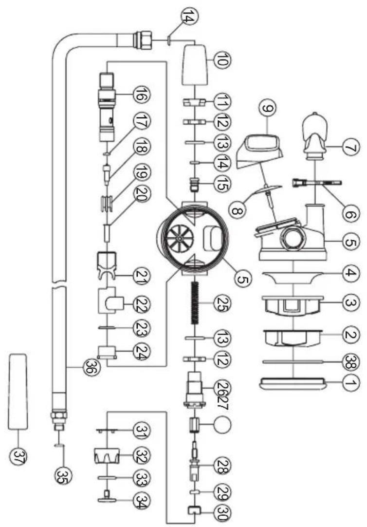
text_image
Technical diagram of a mechanical device with numbered components for identification and assembly reference.S-30
| ITEMNO. | PART NO. DESCRIPTION |
| 1 S30-052 DIAPHRAGM RETAINER | |
| 2 S30-100 PURGE GUARD | |
| 3 S30-081 DIAPHRAGM COVER | |
| 4 S30-062 DIAPHRAGM | |
| 5 S30-221 CASE | |
| 6 RSU116 MOUTHPIECE CLIP | |
| 7 /RSU196 MOUTHPIECE | |
| 8 S30-271 EXHAUST VALVE | |
| 9 S30-011 EXHAUST TEE | |
| 10 S30-030 SLEEVE | |
| 11 S30-260 NUT,DEMAND HOUSING | |
| 12 S30-250 SPACER | |
| 13 017 O-RING | |
| 14 010 O-RING | |
| 15 S30-040 ORIFICE | |
| 16 /S30-022 DEMAND HOUSING | |
| 17 S30-240 DEMAND SEAT | |
| 18 S30-231 DEMAND STEM | |
| 19 S30-210 DEMAND STEM GUIDE | |
| 20 S30-280 DEMAND SPRING GUIDE | |
| 21 S30-073 DEMAND LEVER | |
| 22 S30-092 DEFLECTOR | |
| 23 014 O-RING | |
| 24 S30-110 GRAND RETAINER | |
| 25 S40-060 DEMAND SPRING | |
| 26 S30-171 GRAND NUT | |
| 27 S30-120 PISTON SPRING FOLLOWER | |
| 28 S30-130 ADJ. SCREW | |
| 29 107 O-RING | |
| 30 S30-150 RETAINING SCREW | |
| 31 S30-180 | CLICK RING |
| 32 S30-141 KNOB | |
| 33 113 O-RING | |
| 34 S30-160 SCREW, KNOB | |
| 35 LPU067 | L.P.HOSE(L=30")ASSY |
| 36 OR106 O-RING | |
| 37 /TR-402-372 HOSE COVER | |
| 38 034 O-RING | |
| SPECIFICATIONS | |||||
| DIMENSIONS: | Height: | 2.91 | IN. | 74 | MM |
| Length: | 4.27 | IN. | 108.5 | MM | |
| Width: | 3.86 | IN. | 98 | MM | |
| WEIGHT:(incl. Hose) | 0.794 | LBS. | 360 | GRAM | |
| HOSE: | Length: | 30 | IN. | 76 | CM |
S-40
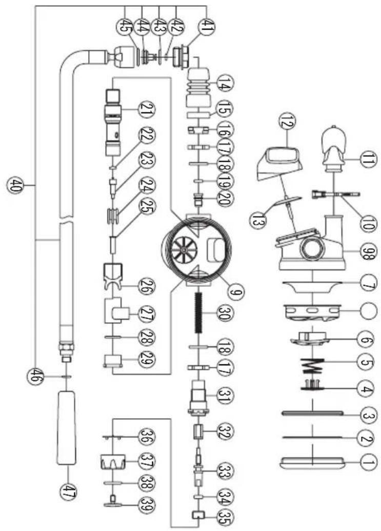
text_image
Technical diagram of a mechanical assembly with numbered components and exploded view, likely for engineering or manufacturing documentation.S-30
| ITEMNO. | PART NO. | DESCRIPTION |
| 1 S30-052 DIAPHRAGM RETAINER | ||
| 2 034 O-RING | ||
| 3 S40-030 SAFTY RING | ||
| 4 S10-030 PURGE BUTTON | ||
| 5 S10-040 PURGE SPRING | ||
| 6 S40-041 RETAINER, PURGE BUTTON | ||
| 7 S40-050 DIAPHRAGM COVER | ||
| 8 S30-062 DIAPHRAGM | ||
| 9 S30-221 CASE | ||
| 10 RSU116 MOUTHPIECE CLIP | ||
| 11 /RSU196 MOUTHPIECE | ||
| 12 S30-011 EXHAUST TEE | ||
| 13 S30-271 EXHAUST VALVE | ||
| 14 S40-080 RUBBER SLEEVE | ||
| 15 /S40-021 NUT RING | ||
| 16 S30-260 NUT, DEMAND HOUSING | ||
| 17 S30-250 SPACER | ||
| 18 017 O-RING | ||
| 19 010 O-RING | ||
| 20 S30-040 ORIFICE | ||
| 21 S30-021 DEMAND HOUSING | ||
| 22 S30-240 DEMAND SEAT | ||
| 23 S30-231 DEMAND STEM | ||
| 24 S30-210 DEMAND STEM GUIDE | ||
| 25 S30-280 DEMAND SPRING GUIDE | ||
| 26 S30-072 DEMAND LEVER | ||
| 27 S30-092 DEFLECTOR | ||
| 28 014 O-RING | ||
| 29 S30-110 GRAND RETAINER | ||
| 30 S40-060 DEMAND SPRING | ||
| 31 S30-171 GRAND NUT | ||
| 32 S30-120 PISTON SPRING FOLLOWER | ||
| 33 S30-130 ADJ. SCREW | ||
| 34 107 | O-RING | |
| 35 S30-150 RETAINING SCREW | ||
| 36 S30-180 CLICK RING | ||
| 37 S30-141 KNOB | ||
| 38 113 | O-RING | |
| 39 S30-160 SCREW, KNOB | ||
| 40 PU119(L=700) | L.P.HOSE ASSY | |
| 41 LPU119-030 END RING | ||
| 42 S16 O-RING | ||
| 43 LPU119-040 INNER TUBE | ||
| 44 011 O-RING | ||
| 45 TR-402-371 HQSE COVER | ||
| SPECIFICATIONS | |||||
| DIMENSIONS: | Height: | 2.91 | IN. | 74 | MM |
| Length: | 4.27 | IN. | 108.5 | MM | |
| Width: | 4.06 | IN. | 103 | MM | |
| WEIGHT:(incl. Hose) | 0.903 | LBS. | 410 | GRAM | |
| HOSE: | Length: | 27.56 | IN. | 70 | CM |
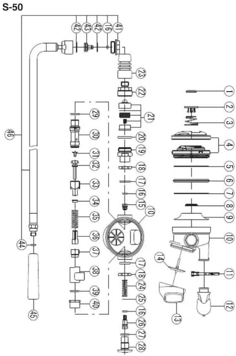
text_image
S-50 46 44 45 29 30 31 32 33 34 35 36 37 38 39 40 23 22 21 20 19 18 17 16 15 10 17 18 19 24 25 16 26 27 28 ① ② ③ ④ ⑤ ⑥ ⑦ ⑧ ⑨ ⑩ ⑪ ⑫ ⑬ ⑭ ⑮ ⑯ ⑰ ⑱ ⑲S-30
| ITEM NO. | PART NO. | DESCRIPTION |
| 1 /S50-241 | DECAL | |
| 2 /S50-081 | PURGE | BUTTON |
| 3 S10-040 | PURGE | SPRING |
| 4 RSU146 | METAL | DIAPHRAGMRETAINER ASSY |
| 5 034 | O-RING | |
| 6 S40-030 | SAFETY | RING |
| 7 S10-050 | WASHER | DIAPHRAGM |
| 8 S50-040 | DIAPHRAGM | DISC |
| 9 S50-050 | DIAPHRAGM | |
| 10 S30-221 | CASE | |
| 11 RSU116 | MOUTHPIECE | CLIP |
| 12 /RSU196 | MOUTHPIECE | |
| 13 S30-011 | EXHAUST | TEE |
| 14 S30-271 | EXHAUST | VALVE |
| 15 S50-200 | ORIFICE | |
| 16 | 010 | O-RING |
| 17 | 017 | O-RING |
| 18 S30-250 | SPACER | |
| 19 S50-210 | FILTER | HOUSING |
| 20 | 020 | O-RING |
| 21 RSU136 | ACTIVE | CARBON FILTER |
| 22 S50-010 | FILTER | CAP |
| 23 S40-080 | RUBBER | SLLEVE |
| 24 S50-090 | ADJ.SPRING | |
| 25 S50-130 | WASHER | ADJ.STEM |
| 26 S50-110 | ADJ.STEM | |
| 27 | 906 | O-RING |
| 28 S50-120 | RETAINING | PLUG |
| 29 | S14 | O-RING |
| 30 S50-020 | DEMAND | HOUSING |
| 31 /S50-191 | DEMAND | SEAT |
| 32 | /S50-182 | DEMAND STEM |
| 33 | S50-030 | DEMAND LEVER |
| 34 S50-170 | WASHER | DEMAND STEM |
| 35 S50-160 | DEMAND | SPRING |
| 36 S50-150 | CHAMBER | DEMAND STEM |
| 37 S50-140 | DEMAND | SCREW |
| 38 S30-092 | DEFLETOR | |
| 39 | 014 | O-RING |
| 40 S10-070 | SQUARE | NUT |
| 41 LPU121-030 | END RING | |
| 42 | S16 | O-RING |
| 43 LPU121-040 | INNER TUBE | |
| 44 | 013 | O-RING |
| 45 TR-402-371 | HOSE COVER | |
| 46 LPU121 LP HOSE ASSY | ||
| SPECIFICATIONS | |||||
| DIMENSIONS: | Height: | 2.91 | IN. | 74 | MM |
| Length: | 4.76 | IN. | 121 | MM | |
| Width: | 4.09 | IN. | 104 | MM | |
| WEIGHT:(incl. Hose) | 0.97 | LBS. | 440 | GRAM | |
| HOSE: | Length: | 27.56 | IN. | 70 | CM |
S-60 / SS-60
text_image
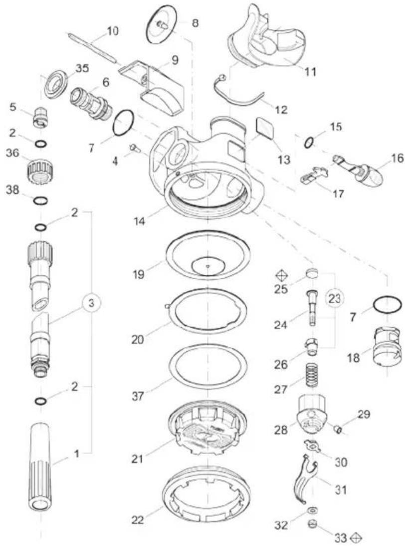
Exploded view diagram of a mechanical device with numbered parts for identificationS-60 / SS-60
| ITEMNO. | PART NO. DESCRIPTION | |
| 1 TR-402-37 HOSE PROTECTOR | ||
| 2 010 O-RING | ||
| 3 S-60-030 L.P.HOSE | ||
| 4 S-60-040 PIN, CASE | ||
| 5 S-60-050 ORIFICE | ||
| 6 S-60-060 BODY, VALVE | ||
| 7 016 O-RING | ||
| 8 S-60-080 EXHAUST VALVE | ||
| 9 S-60-090 EXHAUST TEE | ||
| 10 S-60-100 PIN, COVER EXHAUST | ||
| 11 S-60-110 MOUTHPIECE, BLACK | ||
| 12 0108BK MOUTHPIECE STRAP | ||
| 13 S-60-130 DECAL DIVE/SURFACE | ||
| 14 S-60-140 CASE | ||
| 15 008 O-RING | ||
| 16 S-60-160 FLOW VANE | ||
| 17 S-60-170 FLOW REDUCER | ||
| 18 S-60-180 PLUG | ||
| 19 S-60-190 DIAPHRAGM ASSY | ||
| 20 S-60-200 SLOT RING | ||
| 21 S-60-210 DIAPHRAGM COVER | ||
| 22 S-60-220 RETAINING RING | ||
| 24 S-60-240 STEM | ||
| 25 S-60-250 | L.P. SEAT | |
| 26 S-60-260 POPPET | ||
| 27 S-60-270 DEMAND SPRING | ||
| 28 S-60-280 HOUSING | ||
| 29 S-60-290 PLUG, HOUSING | ||
| 30 S-60-300 INSERT, HOUSING | ||
| 31 S-60-310 | LEVER | |
| 32 S-60-320 | WASHER | |
| 33 ST-003-02 LOCK NUT | ||
| 35 S-60-350 | SPACER | |
| 36 S-60-360 | NUT, JAM | |
| 37 S-60-370 | DIAPHRAGM RING | |
| 38 014 O-RING | ||
| SPECIFICATIONS | |||||
| DIMENSIONS: | Height: | 2.91 | IN. | 74 | MM |
| Length: | 4.27 | IN. | 108 | MM | |
| Width: | 4.09 | IN. | 104 | MM | |
| WEIGHT:(incl. Hose) | 0.33 | LBS. | 150 | GRAM | |
| HOSE: | Length: | 29 | IN. | 74 | CM |
S-70

text_image
Technical schematic diagram of a mechanical assembly with numbered components and labeled partsS-70
| ITEM NO. | PART NO. DESCRIPTION |
| 1 S30-300 DIAPHRAGM RETAINER | |
| 2 034 O-RING | |
| 3 S40-030 SAFTY RING | |
| 4 /S50-241 DECAL | |
| 5 /S50-081 PURGE BUTTON | |
| 6 S10-040 PURGE SPRING | |
| 7 /S70-010 DIAPHRAGM COVER | |
| 8 S30-062 DIAPHRAGM | |
| 9 S30-221 CASE | |
| 10 FSU116 MOUTHPIECE CLIP | |
| 11 /RSU196 MOUTHPIECE | |
| 12 S30-011 EXHAUST TEE | |
| 13 S30-271 EXHAUST VALVE | |
| 14 S40-080 RUBBER SLEEVE | |
| 15 /S40-021 NUT RING | |
| 16 S30-260 NUT, DEMAND HOUSING | |
| 17 S30-250 SPACER | |
| 18 017 O-RING | |
| 19 010 O-RING | |
| 20 S30-040 ORIFICE | |
| 21 /S30-022 DEMAND HOUSING | |
| 22 S30-240 DEMAND SEAT | |
| 23 S30-231 DEMAND STEM | |
| 24 S30-210 DEMAND STEM GUIDE | |
| 25 S30-280 DEMAND SPRING GUIDE | |
| 26 S30-073 DEMAND LEVER | |
| 27 S30-092 DEFLECTOR | |
| 28 014 O-RING | |
| 29 S30-110 GRAND RETAINER | |
| 30 S40-060 DEMAND SPRING | |
| 31 S30-171 GRAND NUT | |
| 32 S30-120 PISTON SPRING FOLLOWER | |
| 33 S30-130 ADJ. SCREW | |
| 34 107 O-RING | |
| 35 S30-150 RETAINING SCREW | |
| 36 S30-180 CLICK RING | |
| 37 S30-141 KNOB | |
| 38 113 O-RING | |
| 39 S30-160 SCREW,KNOB | |
| 40 LPU119(L=700) L.P.HOSE ASSY | |
| 41 LPU119-030 END RING | |
| 42 S16 O-RING | |
| 43 LPU119-040 INNER TUBE | |
| 44 011 O-RING | |
| 45 TR-402-371 HOSE COVER | |
| SPECIFICATIONS | |||||
| DIMENSIONS: | Height: | 2.91 | IN. | 74 | MM |
| Length: | 4.76 | IN. | 121 | MM | |
| Width: | 4.09 | IN. | 104 | MM | |
| WEIGHT:(incl. Hose) | 0.97 | LBS. | 440 | GRAM | |
| HOSE: | Length: | 27.56 | IN. | 70 | CM |
S-80
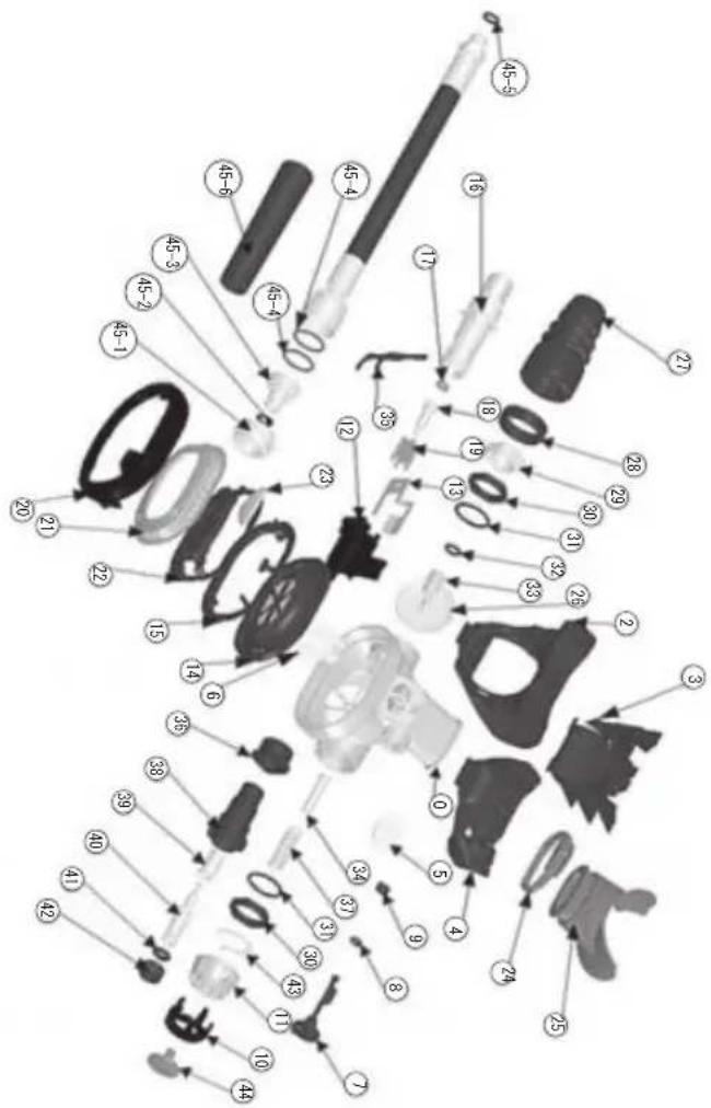
text_image
Exploded view diagram of a mechanical assembly with numbered parts for identificationS-80
| ITEM NO. | PART NO. DESCRIPTION | |
| 1 | /S80-010 | CASE |
| 2 | /S80-020 | EX TEE |
| 3 | /S80-030 | EX TEE FRAME |
| 4 | /S80-040 | UPPER EX TEE |
| 5 | /S80-050 | UPPER EX VALVE |
| 6 | /S80-060 | CHECK VALVE |
| 7 | /S80-070 | FLAP |
| 8 | 007 | O-RING |
| 9 | /S80-080 | FLAP RETAINER |
| 10 | /S80-100 | KNOB RIDGE |
| 11 | /S80-090 | KNOB |
| 12 | /S80-110 | DEFLECTEOR |
| 13 | /S80-120 | HEAT EX PLATE |
| 14 | /S80-130 | DIAPHRAGM |
| 14-1 | /S80-140 | DIAPHRAGM DISK |
| 15 | /S80-150 | DIAPHRAGM RETAINER |
| 16 | /S80-160 | HOUSING |
| 17 | S30-240 | DEMAND SEAT |
| 18 | S30-231 | DEMAND STEM |
| 19 | S30-210 | DEMAND STEM GUIDE |
| 20 | /S80-190 | FACE RING |
| 21 | /S80-210 | METAL COVER |
| 22 | /S80-200 | DIAPHRAGM COVER |
| 23 | /S80-220 | DECAL |
| 24 | ST-004-01 | MOUTHPIECE CLIP |
| 25 | /RSU196 | MOUTHPIECE |
| 26 | S30-271 | EXHAUST VALVE |
| 27 | S40-080 | RUBBER SLEEVE |
| 28 | /S40-021 | NUT RING |
| 29 | S30-260 | NUT, DEMAND HOUSING |
| 30 | S30-250 | SPACER |
| 31 | 017 | O-RING |
| 32 | 010 | O-RING |
| 33 | S30-040 | ORIFICE |
| 34 | S30-280 | DEMAND SPRING GUIDE |
| 35 | S30-073 | DEMAND LEVER |
| 36 | S30-110 | GRAND RETAINER |
| 37 | S40-060 | DEMAND SPRING |
| 38 | S30-171 | GRAND NUT |
| 39 | S30-120 | PISTON SPRING FOLLOWER |
| 40 | S30-130 | ADJ. SCREW |
| 41 | 107 | O-RING |
| 42 | S30-150 | RETAINING SCREW |
| 43 | S30-180 | CLICK RING |
| 44 | S30-160 | SCREW,KNOB |
| 45 | LPU118(L=760) | L.P. HOSE ASSY |
| SPECIFICATIONS |
| DIMENSIONS: Height: 2.56 IN. 65 MMLength: 4.76 IN. 121 MMWidth: 4.09 IN. 104 MMWEIGHT:(incl. Hose) 0.92 LBS. 418 GRAMHOSE: Length: 30 IN. 76 CM |
text_image
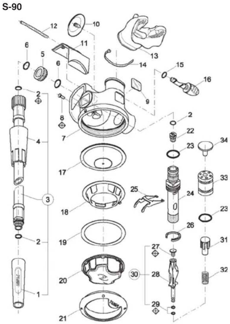
S-90 12 10 6 5 6 11 13 14 15 16 2 8 7 2 22 23 34 4 17 3 25 24 23 18 19 26 27 30 20 28 31 32 29 21S-90
| ITEM NO. | PART NO. DESCRIPTION |
| 1 /S90-010 PROTECTIVE SLEEVE | |
| 2 /010-EP O-RING | |
| 3 /S90-020 L.P. HOSE | cm.75 |
| 4 /S90-030 SLEEVE HOSE | |
| 5 /S90-040 NUT. JAM | UNIF. |
| 6 /014-EP85 O-RING | |
| 7 /S90-050 CASE | |
| 8 /S90-060 PIN. CASE | |
| 9 /S90-070 DECAL V.I. | V.A. |
| 10 /$60-080 EXHAUST | VALVE |
| 11 /S60-090 COVER EXHAUST | |
| 12 /S60-100 PIN | |
| 13 /S60-110 MOUTHPIECE | |
| 14 TR0-108-BK CLIP LIGHT | |
| 15 /008-EP85 O-RING | |
| 16 /S90-080 FLOW VANE | |
| 17 /S60-190 DIAPHRAGM ASSY | |
| 18 /S90-090 WASHER ANTIFRICTION | |
| 19 /S60-370 RING | |
| 20 /S90-100 PURGE COVER | |
| 21 /S90-110 RING | |
| 22 /S60-050 ORIFICE | |
| 23 /016 | O-RING |
| 24 /S90-120 HOUSING | |
| 25 /S90-130 LEVER | |
| 26 /S90-140 RETAINING CLIP KNOB | |
| 27 /S90-150 SEAT | |
| 28 /S90-160 POPPET | |
| 29 /101-EP | O-RING |
| 30 /S90-170 POPPET ASSY | |
| 31 /S90-180 BALANCE | CHAMBER |
| 32 /S60-270 SPRING | |
| 33 /S90-190 PLUG | |
| 34 /S90-200 PLUG | |
| SPECIFICATIONS | |||||
| DIMENSIONS: | Height: | 2.91 | IN. | 74 | MM |
| Length: | 4.76 | IN. | 121 | MM | |
| Width: | 4.09 | IN. | 104 | MM | |
| WEIGHT:(incl. Hose) | 0.33 | LBS. | 150 | GRAM | |
| HOSE: | Length: | 29 | IN. | 70 | CM |
FOREWORD
CONGRATULATIONS! You are now the owner of one of the many fine TUSA products. Your new regulator is built to exacting standards, using only the highest quality materials. For several years now TUSA has been developing the regulators under the ISO9001 International Quality Assurance System. You have purchased the newest, the most advanced regulator for the Sport Scuba Market available today. The TUSA regulator is the first major improvement to the conventional down stream demand valve since 1988. The second stage is constructed of technologically advanced materials and the performance provides exceptional aspiration flow and allows fully adjustable performance to accommodate beginner and professional divers.
Before you use your new regulator, please read this manual carefully. The following warnings, cautions, and notes were written to make it possible for you to enjoy your diving experience with maximum safety.
We at TUSA want you to have many years of dependable service from your new equipment and have many memorable and safe dives. Thank you for purchasing one of our high quality products.
WARNING:
THIS PRODUCT IS A SCUBA DIVING DEVICE AND REQUIRES PROPER TRAINING BEFORE USE.
CE Certified combinations of TUSA Regulators are listed below:
| Name of Regulator | 1st Stage Model No. | 2nd Stage Safe 2nd | |
| Model No. C | Cover Model No | ||
| RS-340 | R-300 (Yoke-DIN) | S-40 | BLACK |
| RS-350 | R-300 (Yoke-DIN) | S-50 | SILVER |
| RS-460II | R-400II (Yoke -DIN) | S-60 | BLACK |
| RS-520 | R-500 (Yoke-DIN) | S-20 | BLACK |
| RS-530 R-500 | (Yoke-DIN) S-30 BLACK | ||
| RS-560 R-500 | (Yoke-DIN) S-60 | GREY | |
| RS-670 | R-600 (Yoke-DIN) | S-70 | SILVER |
| RS-680 | R-600 (Yoke-DIN) | S-80 | BLACK |
| RS-760 | R-700 (Yoke-DIN) | S-60 | GREY |
| RS-790 | R-700 (Yoke-DIN) | S-90 | GREY |
| RS-811 | R-800 (Yoke-DIN) | S-11 | BLACK |
| RS-812 | R-800 (Yoke-DIN) | S-12 | BLACK |
| RS-860 R-800 | (Yoke-DIN) S-60 | GREY | |
| Stage | |
| Cover | |
| SS-11 | YELLOW |
| SS-20 | YELLOW |
| SS-60 | YELLOW |
RS-460II, 560, 760, 790, 811, 812, 860
Notice:
"The PPE (Personal Protective Equipment) mentioned in this User's Manual was submitted to tests for validation of the design and certified according to Art. 10 of Directive 89/686/EEC by RINA - Via Corsica, 12-16128 Genova ITALY, Notified body n 0474. This device is in compliance with EN 250:2000.
The CE marking means the compliance of the device to the Basic Health and Safety Requirements of Annex II of Directive 89/686/EEC. The number 0098 near the CE identifies the Notified Body GL (Germanischer Lloyd), entitled for the EC quality control system for the final product according to Art. 11.A of Directive 89/686/EEC."
RS-340, 350, 520, 530, 670, 680
Notice:
"The PPE (Personal Protective Equipment) mentioned in this User's Manual was submitted to tests for validation of the design and certified according to Art. 10 of Directive 89/686/EEC by ITALCERT - Viale Sarca 336, 20126 Milano ITALY, Notified body n 0426. This device is in compliance with EN 250:2000.
The CE marking means the compliance of the device to the Basic Health and Safety Requirements of Annex II of Directive 89/686/EEC. The number 0426 near the CE identifies the Notified Body ITALCERT, entitled for the EC quality control system for the final product according to Art. 11.A of Directive 89/686/EEC."
TABLE OF CONTENTS
Technical Specification and Performance Page No.
1 R-300, R-300DIN First Stage....1
2 R-400, R-400DIN First Stage 2
3 R-500, R-500 DIN First Stage....3
4 R-600, R-600 DIN First Stage 4
5 R-700, R-700 DIN First Stage 5
6 R-800, R-800 DIN First Stage....6
7 S-11/SS-11Second Stage 7
8 S-12 Second Stage 8
9 S-20/SS-20 Second Stage....9
10 S-30 Second Stage.... 10
11 S-40 Second Stage....11
12 S-50 Second Stage 12
13 S-60/SS-60 Second Stage.... 13
14 S-70 Second Stage 14
15 S-80 Second Stage....15
16 S-90 Second Stage.... 16
SECTION
I Warning - Read Carefully ....20
II Description and Operation 21
2.0 General 21
2.1 First Stage 21
2.2 Second Stage 22
III Pre-Dive Procedures....24
IV After Dive Procedures 25
V Contaminated Water Diving 26
VI Cold Water Diving 26
VII Scheduled Maintenance 27
VIII "Air Refresher" filter replacement 28
SECTION I
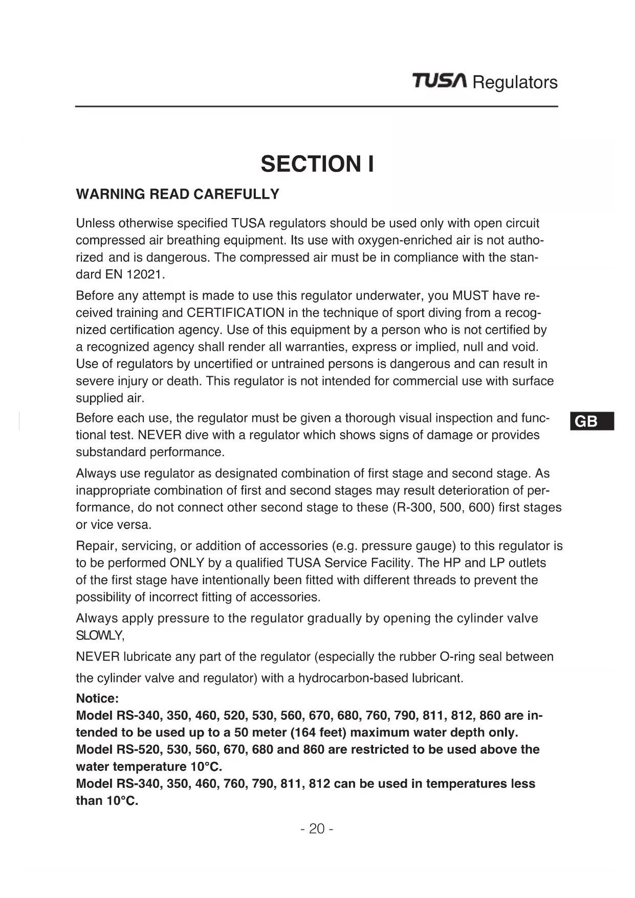
WARNING READ CAREFULLY
Unless otherwise specified TUSA regulators should be used only with open circuit compressed air breathing equipment. Its use with oxygen-enriched air is not authorized and is dangerous. The compressed air must be in compliance with the standard EN 12021.
Before any attempt is made to use this regulator underwater, you MUST have received training and CERTIFICATION in the technique of sport diving from a recognized certification agency. Use of this equipment by a person who is not certified by a recognized agency shall render all warranties, express or implied, null and void. Use of regulators by uncertified or untrained persons is dangerous and can result in severe injury or death. This regulator is not intended for commercial use with surface supplied air.
Before each use, the regulator must be given a thorough visual inspection and functional test. NEVER dive with a regulator which shows signs of damage or provides substandard performance.
Always use regulator as designated combination of first stage and second stage. As inappropriate combination of first and second stages may result deterioration of performance, do not connect other second stage to these (R-300, 500, 600) first stages or vice versa.
Repair, servicing, or addition of accessories (e.g. pressure gauge) to this regulator is to be performed ONLY by a qualified TUSA Service Facility. The HP and LP outlets of the first stage have intentionally been fitted with different threads to prevent the possibility of incorrect fitting of accessories.
Always apply pressure to the regulator gradually by opening the cylinder valve SLOWLY,
NEVER lubricate any part of the regulator (especially the rubber O-ring seal between the cylinder valve and regulator) with a hydrocarbon-based lubricant.
Notice:
Model RS-340, 350, 460, 520, 530, 560, 670, 680, 760, 790, 811, 812, 860 are intended to be used up to a 50 meter (164 feet) maximum water depth only.
Model RS-520, 530, 560, 670, 680 and 860 are restricted to be used above the water temperature 10^ C.
Model RS-340, 350, 460, 760, 790, 811, 812 can be used in temperatures less than 10^ C.
SECTION II DESCRIPTION AND OPERATION
2.0 GENERAL
TUSA Regulators are BALANCED PISTON and BALANCED DIAPHRAGM type SINGLE HOSE REGULATORS. The regulator reduces high pressure air from the scuba cylinder to ambient pressure suitable for breathing, through the operation of first and second stage regulators. The first stage regulator reduces incoming high pressure air, to an intermediate pressure of approximately 135PSI ( ÷ 9.5bar). The second stage regulator, using a diaphragm operated demand valve, further reduces air from intermediate pressure to ambient pressure permitting normal breathing. The first and second stages of the regulator are connected by a low pressure hose. A swivel yoke (TYPE INT) on the first stage body secures the regulator to the cylinder valve, while an O-ring surrounding the outlet orifice on the cylinder valve ensures an airtight connection to the first stage.
2.1 FIRST STAGE
R-300 first stage
In order to achieve natural breathing, a dynamic flow hose with a large inner diameter increases the airflow. The R-300 always supplies the diver with stable air at any tank pressure or depth, delivering maximum breathing ease and comfort for them.
R-400 first Stage
The TUSA R-400 offers a first stage with the balanced diaphragm method. This method features minimum variation in intermediate pressure in response to changes in residual cylinder pressure and depth. The R-400 is engineered for cold water diving (EN-250-2000). It also offers two high high flow LP ports (HFP) that are close to the diaphragm to increase the airflow by approximately 15%.
R-500 first stage
The very popular balanced piston type first stage offers superior reliability for stable air supply regardless of depth or residual pressure.
R-600 and R-600 DRY first stage
With the R-600, offers a compact design weight of just 630g during actual use. This allows the R-670 to only be a total weight of just 1050g for the first and sec-
ond stages. The balanced diaphragm method first stage features minimum variation in intermediate pressure in response to changes in residual cylinder pressure and depth. The ports are in left-right symmetry (H.P. × 2, L.P. × 4) for easier attachment to tanks, even for beginners.
R-700 first Stage
The R-700 is a balanced diaphragm first stage with key design and performance characteristics:
1) Four intermediate pressure ports and two high pressure ports, 2) Balanced first stage, with a built-in antifreeze system, 3) Replaceable HP seat and HP poppet for durability and servicing, 4) Two special high flow LP ports (HFP) close to the diaphragm offer approximately 15% greater air flow, 5) Dry balance chamber prevents water contact with the diaphragm and the spring for superior cold water performance. The R-700 meets the European Standards EN250:2000 requirements for cold water conditions.
R-800 first Stage
The R-800 is a balanced piston type first stage offering superior reliability for stable air supply regardless of depth or residual pressure. It is equipped with four intermediate low pressure ports and two high pressure ports.
2.2 SECOND STAGE
Demand system
* The demand system is designed to significantly reduce rubbing resistance of moving parts and air resistance. The result is smoother and more natural valve opening/closing.
Light weight housing
* The second stage main unit is smaller and lighter to reduce water resistance during diving, thus reducing the load on the face during use. The main body materials are super-tough nylon (heat pliable polyamide resin) reinforced with glass fiber for outstanding hardness and shock resistance. The materials also offer superior tensile strength, dimensional stability, heat resistance, weather resistance and chemical resistance.
Intake resistance
* The second stage includes a director to forcibly guide air from the demand valve. That prevents free flow while significantly lessening intake resistance. The result is
one of the lightest intake resistance values in the industry compared with products from other companies.
New mouthpiece
The new mouthpiece, developed on the basis of ergonomic engineering, further enhances the comfort of bite, fit, and stability. Even with a light bite, a high level of stability is achieved, so there is no fatigue from long periods of usage.
Venturi Adjustment Lever (RS-460, 680, 790, 811, 812, SS-60, 80)
The addition of a venturi adjustment lever allows the regulator to power assist the diver when underwater utilizing the natural venture effect. The diver can also adjust the lever to prevent free flow such as on a surface swim.
Swivel joint (RS-340, 350, 670, 680)
For optimum performance and comfort, a swivel joint is fitted between the second stage and the joint section of the low pressure hose. The swivel joint allows flexibility of the hose for eliminate hose tension at the mouthpiece for a more natural and comfortable bite.
"Air Refresher" filter (RS-350)
There are two types of high tech filter built into the second stage. An active carbon filter cleans the air and absorbs smells, while a metal fiber filer eliminates particles as small as 100 microns. This makes sure that the cleanest and safest air is supplied to the diver.
S.E.A. -Sequential Exhaust Assist [PAT.P.] (RS-680)
The Sequential Exhaust Assist (S.E.A.) is an auxiliary exhaust valve, located on top of the S-80 elliptical case to decrease primary exhaustion resistance.
Click Spring Adjustment (RS-670, 680)
The click spring adjustment feature is exclusive to TUSA. It is a 5 position adjustment knob designed to better control breathing resistance.
Adjustable control knob (RS-812)
The adjustable knob designed to better control breathing resistance.
SECTION III PRE-DIVE PROCEDURES
WARNING
Do not attempt to connect low pressure hoses to the high pressure ports with the use of an adapter. Improper connection will cause damage to the equipment and could result in serious personal injury. Low pressure components are not intended to withstand pressures greater than 28Bar ÷ (400 PSI). When installing your accessory hoses, avoid damaging the O-ring. Tighten gently, but firmly into the first stage housing.
SCUBA complying with EN 250 are not intended for more than one user to breathe from at the same time.
If SCUBA are configured and used by more than one diver at the same time, then the cold water and breathing performances may not fulfil the requirements of EN 250.
RS-350, 340
Always connect the Octopus Regulator to the portmarked with SS. Connecting to any other port is strictly prohibited.
PRE-DIVE OPERATING INSTRUCTIONS
- Position the tank valve so the outlet points toward the diver.
- Remove the dust cap from the first stage inlet and place the yoke (or DIN adaptor) in the center of the cylinder valve connection.
- Position the first stage body so that the second stage hose goes over the right shoulder of the diver.
- Hand-tighten the yoke screw or DIN adoptorscrew.
- Check all the hose connections to the first and second stages. If they can be loosened by hand, they should be tightened with a wrench before pressurizing.
- Check the submersible pressure gauge to make sure it indicates zero pressure.
- Open the tank valve slowly to gradually allow air into the regulator.
NOTE: During this operation, depress the second stage purge button to reduce shock to the valve mechanism. Do not perform this operation in a cold environment below 10^ C ( 50^ F). Performing this in a cold environment may cause “freeze-up” of the regulator which can render it inoperable. If this occurs, you should contact a TUSA authorized service center.
-
Check the submersible pressure gauge to ensure that it indicates the proper tank pressure.
-
Check the tank/regulator connection for leakage. If leakage exists, it may be caused by incorrect mounting of the regulator on the tank valve, or by a damaged O-ring in the tank valve.
- To confirm that the regulator delivers air properly, first exhale through the mouthpiece to blow any foreign matter out of the second stage, then inhale. A few of these breathing cycles should immediately indicate proper function.
- If you are using the second stage as an Octopus regulator, it is strongly recommended to utilize an Octopus plug to prevent any foreign matter from entering the second stage through the mouthpiece.
- When the second stage is not in your mouth, uncontrolled air delivery can take place. This can be stopped by turning the second stage upside down and allowing it to fill with water. Should the air delivery continue, abort the dive and have the regulator inspected by a TUSA Authorized Service Center.
SECTION IV AFTER DIVE PROCEDURES
Providing the best possible preventative and routine maintenance before, after, and between dives will help to ensure the maximum life of your TUSA Regulator. To achieve this goal, there are a number of simple, yet important, routine maintenance procedures that should be followed by the diver after each use of the equipment. The following procedures should be diligently followed in order to obtain the maximum life of serviceability from your regulator.
- After each day of diving, the regulator must be cleaned, inspected, and prepared for the next use, or for storage. As soon as the regulator is removed from the ai cylinder, reinstall the dust cap over the regulator inlet port. This cap is normally attached to the First Stage and therefore has been under water. Be sure to dry a the water out of this cap before securing it over the inlet port. Ensure that the O-ring if fitted, is in place inside the dust cap.
- As soon as possible after diving, the regulator should be soaked in warm, not over 50^ C ( 122^ F) water to remove salt and mineral deposits. The preferred method is to attach the regulator to a charged air cylinder, open the cylinder valve, and thoroughly soak both the first and second stage regulators. Pay particular attention to directing water into the mainspring cavity of the first stage regulator, the second stage mouthpiece, and the holes in the second stage cover. Depress the purge button several times while the regulator is submerged in water. Dry the regulator by pressing on the purge button with the mouthpiece pointing down. Place the dust cap in position in the yoke, or over the DIN screw.
Soaking regulator parts in warm water will remove more salt and mineral deposits than will conventional rinsing. It will loosen deposits on interior components that rinsing will not (If no charged air cylinder is available, follow the above procedure but be very careful NOT to depress the purge button, or leave dust cap off, when the regulator is submerged in water. Failure to do this will allow water to enter both regulator stages and may result in internal corrosion).
Simply soak the entire exterior of the first stage thoroughly, and proceed as above when cleaning the second stage.
- Store in a clean equipment box, or as an alternative, seal inside a plastic bag. Store in a clean dry place.
- Lightly lubricate the yoke screw with silicone grease.
- Never store the regulator while it is still connected to the diving cylinder.
- Do not use any type of solvent to clean any part of the regulator. Do not expose any part of the regulator to silicone spray, as some aerosol propellants attack or degrade rubber and plastic material.
- Do not carry the diving cylinder by the regulator as such abuse will eventually damage the regulator or the cylinder valve. Do not expose the regulator to unnecessary shocks or impact.
SECTION V CONTAMINATED WATER DIVING
Sophisticated diving gear designed for use in contaminated water provides constant positive pressure inside the regulator case and utilizes redundant exhaust valve passages. TUSA regulators are not designed to provide this requirement and therefore are not recommended for use in contaminated water diving.
SECTION VI RS-350/340/680/790 DRY USE IN COLD WATER DIVING
This is important information. Be sure to read it.
WARNING:
RS-350/340/680/790DRY regulators for the European market have passed the cold water performance test (water temperature: 4^ C) specified by EN250.
When using these regulators in cold water at temperatures of 10^ C or below, be sure to observe the following notices.
General Caution Items
* Before you use the regulator, be sure to receive specialized instruction on cold water diving from a diving instruction authority so that you learn the necessary skills and knowledge.
* Be sure to receive orientation for the diving environment.
* Be sure to obey the instructions of your instructors and guides.
Equipment Handling Caution Items
The conditions for freezing up of the regulator change in accordance with the breathing conditions of its user (breathing volume, breathing speed, number of breaths) and the environment conditions before and during use.
* Do not take shallow, fast breaths. It makes freezing occur more easily.
* To avoid free flow condition due to freezing NEVER push the purge button while the regulator is outside of the water.
* Store the regulator at room temperature. When diving, store your regulator in its bag to keep it warm until just before use.
* When waiting between dives, always keep your regulator warm. Do not leave it out in a cold environment.
* Your regulator may freeze depending on the conditions. If your regulator freezes, it may free flow. If it does, use breathing technique for free flow conditions.
* When diving in water temperatures of 10^ C or below, always swim at a safe depth from which you can perform an emergency swimming ascent.
SECTION VII SCHEDULED MAINTENANCE
-
Do not assume that a regulator is in good working order because of storage or infrequent use. Remember that either prolonged or improper storage can still result in internal corrosion and/or deterioration of O-ring seals.
-
Have your regulator cleaned and adjusted frequently. The frequency will depend upon the amount of use given the regulator and the conditions of use. However, TUSA strongly recommends inspection, overhaul and scheduled parts replacement at least once a year in order to ensure the optimum functioning of the regulator. Certain parts require replacement at specific intervals. This work must be carried out by a competent service facility. Use as rental equipment and/or in salt, chlorinated (swimming pool), or polluted fresh water might require cleaning and overhaul of the regulator every three to six months. Remember that chlorinated
water is an especially bad environment for regulators as the chlorine chemically deteriorates the neoprene rubber components.
- Regularly inspect the sintered filter in the inlet port of the first-stage. If it is discolored or corroded, replacement by trained personnel is required. Also, at this point, the entire regulator may need a general overhaul with replacement of all soft seals and non-reusable components. Rust or aluminium oxide (grey powder) deposits on the sintered filter are usually an indication that salt water has entered the air cylinder and caused internal corrosion. At this time you air cylinder(s) should be internally inspected by a qualified and competent service control and then cleaned, or hydrostatically tested as required.
- Do not disassemble your regulator. There are no adjustments which can or need to be carried out by the user. Take the regulator to a qualified TUSA dealer or service facility for service. Ensure that only original parts are used to service your regulator.
SECTION VIII "AIR REFRESHER" FILTER REPLACEMENT (RS-350)
-
The timing for replacing the filter is the same as for the equipment overhaul. TUSA strongly recommends that you have your filter replaced every 100 dives, or a year after purchase or the last overhaul (or filter replacement) regardless of the conditions of use. The TUSA repair facility will replace the filter during the overhaul, so be sure to have your equipment overhauled at the specified interval. If you have already had your equipment overhauled and only wish to replace the filter, you must also have this work carried out at a specialist outlet or TUSA facility.
-
Never try to overhaul the equipment or replace the "Air Refresher" filter yourself, as it could cause a serious accident.
FINAL NOTE
Service your Regulator often- your personal safety and the mechanical integrity of your regulator depend on it.
EINLEITUNG
T.E.C. [TABATA EUROPE CORPORATION] B.V.
Den Brielstraat 2b, 1055RV, Amsterdam, The Netherlands
TEL 020-58-11-280/FAX 020-58-11-285 (Country Code=31)
TABATA U.S.A. INC.
2380 Mira Mar Ave., Long Beach, CA 90815, U.S.A.
TEL 562-498-3708/FAX 562-498-1390 (Country Code=1)
TABATA AUSTRALIA PTY. LTD.
4D James Ruse Business Park 6 Boundary Road, Northmead, Sydney, NSW 2152, Australia
TEL 02-9890-4555/FAX 02-9890-5222 (Country Code=61)
No.256, Huanqu W. Rd., Dayuan Township, Taoyuan County 337, Taiwan. (R.O.C.)
TEL.03-386-5100/FAX.03-386-5103 (Country Code=886)
www.tusa.com
© Copyright TABATA CO., LTD