
Genius G750 - Battery charger NOCO - Free user manual and instructions
Find the device manual for free Genius G750 NOCO in PDF.
| Product Type | Smart Battery Charger |
| Brand | NOCO |
| Model | Genius G750 |
| Dimensions (W x D x H) | 113 x 68 x 39 mm |
| Weight | 0.196 kg |
| AC Input Voltage | 220-240 V, 50-60 Hz |
| Max Power | 13 W |
| Charge Current | 750 mA (12 V) / 750 mA (6 V) |
| Charge Voltage | 14.5 V (12 V) / 7.25 V (6 V) |
| Compatible Battery Types | 6 V and 12 V lead-acid (Wet, Gel, MF, CA, EFB, AGM) and lithium-ion |
| Battery Capacity | 2-30 Ah (charging), maintenance for all sizes |
| Number of Charge Stages | 8 stages |
| Charge Modes | Standby, Normal 12 V, Normal 6 V |
| Protections | Reverse polarity, spark-proof, overcharge, overcurrent, undervoltage, overtemperature |
| Protection Rating | IP60 |
| Cooling | Natural convection |
| Ambient Operating Temperature | 0°C to +40°C |
| DC Cable Length | Approx. 1900 mm (75 in) |
| Advanced Features | Recovery, optimization, maintenance, energy saving, diagnostics, voltage compensation |
| Box Contents | Charger, HD clamp, eyelet terminal connectors, user manual, warranty guide |
| Maintenance and Cleaning | Clean with a dry cloth; do not immerse in water |
| Safety | Read manual before use; do not expose to moisture; use in a well-ventilated area |
Frequently Asked Questions - Genius G750 NOCO
User questions about Genius G750 NOCO
0 question about this device. Answer the ones you know or ask your own.
Ask a new question about this device
Download the instructions for your Battery charger in PDF format for free! Find your manual Genius G750 - NOCO and take your electronic device back in hand. On this page are published all the documents necessary for the use of your device. Genius G750 by NOCO.
USER MANUAL Genius G750 NOCO
Failure to follow the instructions may result in ELECTRICAL SHOCK, EXPLOSION, or FIRE, which may result in SERIOUS INJURY, DEATH, DAMAGE TO DEVICE or PROPERTY. Do not discard this information.
Welcome. Thank you for buying the NOCO Genius® G750. Read and understand the User Guide before operating the charger. For questions regarding our chargers, view our comprehensive support information at www.no.co/support. To contact NOCO for personalized support (not available in all areas), visit www.no.co/connect.
What's In The Box.
• G750 Smart Charger
• (1) Battery Clamp Connectors
• (1) Eyelet Terminal Connectors
- User Guide
• Information Guide and Warranty
Contacting NOCO.
Phone: 1.800.456.6626
Email: support@no.co
Mailing Address: 30339 Diamond Parkway, #102
Glenwillow, OH 44139
United States of America
About G750. The NOCO Genius® G750 represents some of the most innovative and advanced technology on the market, making each charge simple and easy. It is quite possibly the safest and most efficient charger you will ever use. The G750 is designed for charging all types of 6V & 12V lead-acid batteries, including Wet (Flooded), Gel, MF (Maintenance-Free), CA (Calcium), EFB (Enhanced Flooded Battery), and AGM (Absorption Glass Mat) batteries. It is suitable for charging battery capacities from 2 to 30 Amp-Hours and maintaining all battery sizes.
Getting Started. Before using the charger, carefully read the battery manufacturer's specific precautions and recommended rates of charge for the battery. Make sure to determine the voltage and chemistry of the battery by referring to your battery owner's manual prior to charging.
Mounting. The G750 is a direct wall plug-in charger, and it is important to keep in mind the distance to the battery. The DC cable length from the charger, with either the battery clamp or eyelet terminal connectors, is approximately 75-inches (1,900mm).
Charging Modes. The G750 has three (3) modes: Standby, 12V NORM, and 6V NORM. Some charge modes must be pressed and held for three (3) seconds to enter the mode. These “Press and Hold” modes are advanced charging modes that require your full attention before selecting. “Press and Hold” are indicated on the charger by a red line. It is important to understand the differences and purpose of each charge mode. Do not operate the charger until you confirm the appropriate charge mode for your battery. Below is a brief description:
| Mode Explanation | |
| Standby | In Standby mode, the charger is not charging or providing any power to the battery. Energy Save is activated during this mode, drawing microscopic power from the electrical outlet. When selected, an orange LED will illuminate. |
| No Power | |
| 12V NORM | For charging 12-volt Wet Cell, Gel Cell, Enhanced Flooded, Maintenance-Free and Calcium batteries. When selected, a white LED will illuminate. |
| 14.5V | 750mA | 2-30Ah Batteries | |
| 6V NORM Press & Hold | For charging 6-volt Wet Cell, Gel Cell, Enhanced Flooded, Maintenance-Free and Calcium batteries. When selected, a white LED will illuminate. |
| 7.25V | 750mA | 2-30Ah Batteries | |

Using 6V NORM. [Press & Hold]
6V NORM charge mode is designed for 6-volt lead-acid batteries only, like Wet Cell, Gel Cell, Enhanced Flooded, Maintenance-Free and Calcium batteries. Consult the battery manufacturer before using this mode.
CAUTION. THIS MODE IS FOR 6-VOLT LEAD-ACID BATTERIES ONLY.
Connecting to the Battery.
Do not connect the AC power plug until all other connections are made. Identify the correct polarity of the battery terminals on the battery. The positive battery terminal is typically marked by these letters or symbol (POS,P,+). The negative battery terminal is typically marked by these letters or symbol (NEG,N,-). Do not make any connections to the carburetor, fuel lines, or thin, sheet metal parts. The below instructions are for
a negative ground system (most common). If your vehicle is a positive ground system (very uncommon), follow the below instructions in reverse order.
1.) Connect the positive (red) battery clamp or eyelet terminal connector to the positive (POS,P,+) battery terminal.
2.) Connect the negative (black) battery clamp or eyelet terminal connector to the negative (NEG,N,-) battery terminal or vehicle chassis.
3.) Connect the battery charger's AC power plug into a suitable electrical outlet. Do not face the battery when making this connection.
4.) When disconnecting the battery charger, disconnect in the reverse sequence, removing the negative first (or positive first for positive ground systems).
Begin Charging.
1.) Verify the voltage and chemistry of the battery.
2.) Confirm that you have connected the battery clamps or eyelet terminal connectors properly and the AC power plug is plugged into an electrical outlet.
3.) The charger will begin in Standby mode, indicated by an orange LED. In Standby, the charger is not providing any power.
4.) Press the mode button to toggle to the appropriate charge mode (press and hold for three seconds to enter an advanced charge mode) for the voltage and chemistry of your battery.
5.) The mode LED will illuminate the selected charge mode and the Charge LEDs will illuminate (depending on the health of the battery) indicating the charging process has started.
6.) The charger can now be left connected to the battery at all times to provide maintenance charging.
Understanding Charge LEDs.
The charger has one (1) Charge LED. This Charge LED indicates the connected battery(s) state-of-charge (SOC). See the explanation below:

| LED Explanation | |
| Pulsing Red LED | The Charge LED will slowly pulse “on” and “off” when the battery is less than 75% fully charged. |
| Pulsing Green LED | The Charge LED will slowly pulse “on” and “off” when the battery is less than 90% charged. |
| Solid Green LED | When the battery is 100% charged, the Charge LED will be solid green. |
| Maintenance Green LED | During maintenance charging, the 100% Charge LED will pulse “on” and “off” slowly. When the battery is topped off and fully charged again, the 100% Charge LED will turn solid green. The charger can be left connected to the battery indefinitely. |
Understanding Advanced Diagnostics.
Advanced Diagnostics is used when displaying Error Conditions. It will display a series of blink sequences that help you identify the cause of the error and potential solutions.
All Error Conditions are displayed with the Error LED and Standby LED flashing back and forth. The number of flashes between each pulse denotes a potential Error Condition (except reverse polarity and low-voltage battery).
| Error Reason/Solution | |
| Single Flash | Battery will not hold a charge. Have battery checked by a professional. |
| Double Flash | Possible battery short. Have battery checked by a professional. |
| Triple Flash | Battery voltage is too high for the selected charge mode. Check the battery and charge mode. |
| Error LED Solid Red | Reverse polarity. Reverse the battery connections. |
| Standby Solid Orange | Battery voltage is too low for charge to detect or charger is in supply. Jumpstart the battery to raise the battery voltage. |

Memory
Returns to last selected mode when restarted

Interactive
Alters the charging process based on organic battery feedback

Recovery
Applies a high-voltage pulse charge when low-voltage, sulfation or lost capacity is detected

Safe
Protects against reverse polarity, sparks, overcharging, overcurrent, open-circuits, short-circuits and overheating

Fast
Charges two times faster than traditional battery chargers

Compensation
Adjusts for varying A/C line voltage for consistent charging

Rugged
Dirt, water, UV, impact and crush resistant

Compact
High-frequency energy conversion for ultra-compact, lightweight and portable charger

Start-Stop
Counteracts increased cyclic energy demands placed on batteries in micro-hybrid vehicles

Firewall
Multi-level safety barrier that prevents abnormal and unsafe conditions

Optimization
Stabilizes internal battery chemistry for increased performance and longevity

Maintenance Plus
Keeps the battery fully charged without overcharging allowing the charger to be safely connected indefinitely

Energy Save
Minimizes energy consumption when full power is not needed

Load Tracking
Charge LEDs dynamically track the batteries state-of-charge when a load outpaces the charge current

Diagnostics
Intuitive visual diagnostic tool for detecting reverse polarity, low-voltage or damaged batteries

CANBUS
Automatically enables the charging port to charge CANBUS systems

Thermal Monitor
Internal temperature sensors adjust charge based on ambient climate
line
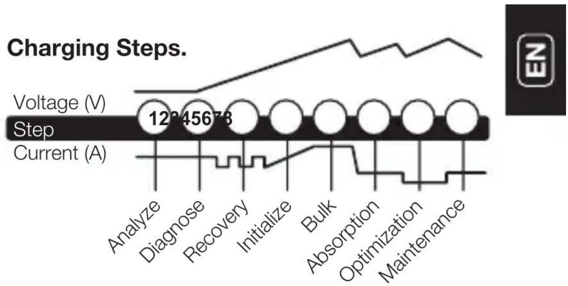
| Step | Voltage (V) | Current (A) | | ------------ | ----------- | ----------- | | Analyze | 12345678 | - | | Diagnose | - | - | | Recovery | - | - | | Initialize | - | - | | Bulk | - | - | | Absorption | - | - | | Optimization | - | - | | Maintenance | - | - |Step 1 & 2: Analyze & Diagnose
Checks the battery's initial condition, including voltage, state-of-charge and health, to determine if the battery is stable before charging.
Step 3: Recovery
Initializes the Recovery desulfation process (if needed) for deeply discharged or sulfated batteries by pulsing small amounts of current.
Step 4: Initialize
Starts the charging process with a gentle (soft) charge.
Step 5: Bulk
Begins the Bulk charging process based on the condition of the battery and returns 80% of the battery's capacity.
Step 6: Absorption
Brings the charge level to 90% by delivering small amounts of current to provide a safe, efficient charge. This limits battery gassing and is essential to prolonging battery life.
Step 7: Optimization
Finalizes the charging process and brings the battery to maximum capacity. In this step, the charger utilizes multi-layered charging profiles to fully recapture capacity and optimize the specific gravity of the battery for increased run time and performance. The charger will switch to Maintenance if the battery tells the charger that more current is needed.
Step 8: Maintenance
Continuously monitors the battery to determine when a maintenance charge should be initiated. If the battery voltage falls below its target threshold, the charger will restart the Maintenance cycle until voltage reaches its optimal state and then discontinues the charge cycle. The cycle between Optimization and Maintenance is repeated indefinitely to keep the battery at full charge. The battery charger can be safely left connected indefinitely without the risk of overcharging.
Charging Times.
The estimated time to charge a battery is shown below. The size of the battery (Ah) and its depth of discharge (DOD) greatly affect its charging time. The charge time is based on an average depth of discharge to a fully charged battery and is for reference purposes only. Actual data may differ due to battery conditions. The time to charge a normally discharged battery is based on a 50% DOD.
| Battery Size Approx. Time to Charge In Hours | ||
| 6V | 12VAh | |
| 8 | 5.3 | 5.3 |
| 12 | 8.0 | 8.0 |
| 18 | 12.0 | 12.0 |
| 24 | 16.0 | 16.0 |
| 30 | 20.0 | 20.0 |
Technical Specifications.
| Input Voltage AC: | 220-240, 50-60Hz |
| Working Voltage AC: | 220-240, 50-60Hz |
| Efficiency: | 85% Approx. |
| Power: | 13W Max |
| Charging Voltage: | Various |
| Charging Current: | 750mA (12V), 750mA (6V) |
| Low-Voltage Detection: | 2V (12V), 2V (6V) |
| Back Current Drain: | <5mA |
| Ambient Temperature: | 0°C to +40°C |
| Charger Type: | 8 Step, Smart Charger |
| Type of Batteries: | 6V & 12V |
| Battery Chemistries: | Wet, Gel, MF, CA, EFB, AGM. |
| Battery Capacity: | 2-30Ah (12V), 2-30Ah (6V), Maintains All Battery Sizes |
| Housing Protection: | IP60 |
| Cooling: | Natural Convection |
| Dimensions (L x W x H): | 4.45 x 2.67 x 1.54 Inches |
| Weight: | 0.49 Pounds |

Français
NOCO EU genius®
G750 v2.0
United States of America
United States of America
À propos de G750. Acerca de G750. El NOCO
United States of America
United States of America
United States of America
United States of America
E-post: support@no.co
E-postadress: 30339 Diamond Parkway, #102
Glenwillow, OH 44139
United States of America
United States of America
30339 Diamond Parkway, #102
Glenwillow, OH 44139
United States of America
1.800.456.6626
support@no.co
30339 Diamond Parkway, #102
Glenwillow, OH 44139
United States of America
no.co
NPD03212014B
- What's In The Box.
- Contacting NOCO.
- Using 6V NORM. [Press & Hold]
- Connecting to the Battery.
- Begin Charging.
- Understanding Charge LEDs.
- Understanding Advanced Diagnostics.
- Memory
- Interactive
- Recovery
- Safe
- Fast
- Compensation
- Rugged
- Compact
- Start-Stop
- Firewall
- Optimization
- Maintenance Plus
- Energy Save
- Load Tracking
- Diagnostics
- CANBUS
- Thermal Monitor
- Step 1 & 2: Analyze & Diagnose
- Step 3: Recovery
- Step 4: Initialize
- Step 5: Bulk
- Step 6: Absorption
- Step 7: Optimization
- Step 8: Maintenance
- Charging Times.
- Français
- NOCO EU genius®
- G750 v2.0
- À propos de G750. Acerca de G750. El NOCO
Brand : NOCO
Model : Genius G750
Category : Battery charger