EBX8001CA - Blower RedMax - Free user manual and instructions
Find the device manual for free EBX8001CA RedMax in PDF.

User questions about EBX8001CA RedMax
0 question about this device. Answer the ones you know or ask your own.
Ask a new question about this device
Download the instructions for your Blower in PDF format for free! Find your manual EBX8001CA - RedMax and take your electronic device back in hand. On this page are published all the documents necessary for the use of your device. EBX8001CA by RedMax.
USER MANUAL EBX8001CA RedMax
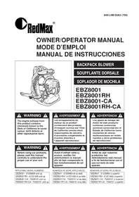
Instructions contained in warnings within this manual and warning seals marked with a symbol on the blower concern critical points which must be taken into consideration to prevent possible serious bodily injury, and for this reason you are requested to read all such instructions carefully and follow them without fail.

Note that there may be times when warning seals peel off or become soiled and impossible to read. If this happens, you should contact the dealer from which you purchased the product to order new seals and affix the new seal(s) in the required location(s).
NOTES ON TYPES OF WARNINGS

WARNING
Instructions labeled as shown at left, concern critical steps or procedures which must be followed in order to prevent accidents which could lead to serious bodily injury or death. This mark is used to indicate instructions which must be followed without exception.

IMPORTANT
Instructions labeled as shown at left concern steps or procedures which, if not followed correctly, could lead to mechanical failure, breakdown, or damage.

NOTE
Used to label supplementary instructions designed to provide hints or directions useful in the use of the product.
Contents
- Parts location.. 4
- Specifications 4
- Warning labels on the machine 6
- Symbols on the machine 8
- For safe operation 10
- Set up 22
7.Fuel 24 - Operation 30
9.Maintenance 34
10.Storage. 42 - Disposal 42
- Troubleshooting guide 44
- Parts list 45

SECURITE
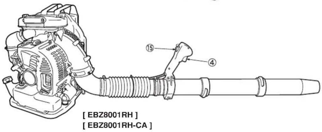
- Frame
- Shoulder Strap
- Spark Plug Cap
- Throttle Lever
- Stop Switch (behind)
6.Net - Choke Lever
- Air Cleaner
-
Volute Case
-
"CAUTION" Label
- "CAUTION" Label (behind)
- Elbow
- Fuel Tank
- Recoil Starter
- Ignition Switch
- Engine Cover
- Intake Cup
2. Specifications
English
■MODEL EBZ8001/EBZ8001RH/EBZ8001-CA/EBZ8001RH-CA
| Dimensions (L x W x H) mm (in) |
| EBZ8001/EBZ8001-CA 390x540x496 (15.4x21.3x19.5) |
| EBZ8001RH/EBZ8001RH-CA 390x490x496 (15.4x19.3x19.5) |
| Dry Weight kg (lbs) 11.5 (25.4) |
| Fuel Tank Capacity liter (fl. oz) 2.3 (77.7) |
| Engine Type Air cooled 2-cycle gasoline engine |
| Piston Displacement cm³ (cu. in) 71.9 (4.39) |
| Air Filter 2-stage fresh flow filter system |
| Carburetor (Diaphragm) valve type Rotary |
| Ignition System Digital ignition |
| Spark Plug NGK CMR7H (Noise-proof) |
| Muffler Spark arrester equipped |
| Operating Engine Speed rpm 2000 to 6700 |
| Fuel Consumption liter/h (fl. oz/h) 1.9 (64.3) |
| Average Air Volume (w/std Pipe) cu. m/min (cfm) 19.4 (685) |
| Max. Air Volume (w/o Pipe) cu. m/min (cfm) 25.9 (915) |
| Max. Air Velocity m/sec (mph) 90 (201) |
| Durability Period hrs. 300 |
| Noise Level (50 Feet ANSI B175. 2-2000) dB(A) 77 |
| Specifications are subject to change without notice |
Français
3. Warning labels on the machine
(1) Read owner's manual before operating this machine.
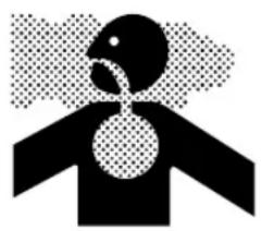
(2) Wear head, eye and ear protection.
(3) Handling this machine improperly could result in accidents causing serious injury or death. Read this manual carefully and practice using the blower until you are fully acquainted with all operations and have learned to use it correctly.

IMPORTANT
If warning label peel off or become soiled and impossible to read, you should contact the dealer from which you purchased the product to order new labels and affix them in the required location(s).

WARNING
Never modify your machine.
We won't warrant the machine, if you use the remodeled machine or you don't observe the proper usage written in the manual.
Français
4. Symbols on the machine
(a)

(b)

(c)
For safe operation and maintenance, symbols are carved in relief on the machine. According to these indications, please be careful not to make a mistake.
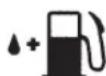
(a) The port to refuel the "MIX GASOLINE"
Position: FUEL TANK CAP
(b) The direction to close the choke
Position: INTAKE CUP
(c) The direction to open the choke
Position: INTAKE CUP
EBZ8001/EBZ8001RH
IMPORTANT ENGINE INFORMATION
THIS ENGINE CONFORMS TO 2007*1 U.S. EPA REGULATIONS FOR SMALL NONROAD ENGINES COMPLIANCE PERIOD : CATEGORY A ENGINE FAMILY : 7KZXS.0725PQ ; EM² ENGINE DISPLACEMENT : 72cc
REFER TO OWNER'S MANUAL FOR MAINTENANCE, SPECIFICATIONS AND ADJUSTMENTS. MANUFACTURED:

ZENOAH CO.,LTD.
USE JASO FC OR ISO EGC GRADE 50:1 OIL
EBZ8001-CA/EBZ8001RH-CA
IMPORTANT EMISSIONS INFORMATION
THIS ENGINE MEETS U.S. EPA PH2 AND 2007 CALIFORNIA EXH AND EVP EMISSION REGULATIONS FOR SI SORE'S. COMPLIANCE PERIOD: CATEGORY A ENGINE FAMILY:7KZXS.0725PQ ENGINE DISPLACEMENT:72cc EMISSION CONTROL SYSTEM:EXH:EM/EVP:SP*3 REFER TO OWNER'S MANUAL FOR MAINTENANCE, SPECIFICATIONS AND ADJUSTMENTS. MANUFACTURED:

ZENOAH CO.,LTD.
USE JASO FC OR ISO EGC GRADE 50:1 OIL.
1: The year will be changed every year of manufacturing.
2: The initial number will be changed every year of manufacturing.
*3: SP : Sealed tank made of HDPE or PE.
Français
- Read this Blower Owner/Operator Manual carefully. Be sure you understand how to operate this unit properly before you use it. Failure to do so could result in serious injury.
- Be sure to keep this manual handy so that you may refer to it later whenever any questions arise. Also note that you are requested to contact the dealer from whom you purchased the product for assistance the event that you have any questions which cannot be answered herein.
- Always be sure to include this manual when selling, lending, or otherwise transferring the ownership of this product.
- Do not lend or rent your machine without the owner's manual.
- Be sure that anyone using your unit understands the infomation contained in this manual.
- Never let a child under 13 years old use the machine.
WORKING CONDITION
- Refrain from operating the blower if you are tired, ill, or upset, or if you are under the influence of alcohol, drugs or medication.
- To reduce the risk of hearing loss associated with sound level(s), hearing protection is required.
- To reduce the risk of injury associated with thrown objects, always wear eye protection and foot protection. Eye protection should meet the requirements of ANSI Z87.1.
- To reduce the risk of injury associated with the inhalation of dust, use a face filter mask in dusty conditions.
- Wear sturdy rubber-soled shoes or shoes with some other form of anti-slip protection to help protect you against falling.
- To reduce the risk of injury associated with objects being drawn into air intake and rotating parts, do not wear loose clothing, scarves, neck chains, hair longer than shoulder length, and the like.
- Prolonged use of a blower, exposing the operator to vibrations and cold may produce whitefinger disease (Raynaud's phenomenon), which symptoms are tingling and burning sensations followed by loss of color and numbness in the fingers. All factors which contribute to whitefinger disease are not known, but cold weather, smoking diseases or physical conditions as well as long periods of exposure to
A VERTISSEMENT
5. For safe operation

vibration are mentioned as factors. In order to reduce the risk of whitefinger disease, the following precautions are strongly recommended;
a) Keep your body warm. Never use blower during rains.
b) Wear thick anti-vibration gloves.
c) Take more than 5 minutes of break in warm place frequently.
d) Maintain a firm grip at all times, but do not squeeze the handles with constant, excessive pressures.
e) If you feel discomfort, redness and swelling of your fingers or any other part of your body, see a doctor before getting worse.
- The ignition system of your unit produces an electromagnetic field of a very low intensity. This field may interfere with some pacemakers. To reduce the risk of serious or fatal injury, persons with pacemaker should consult their physician and the pacemaker manufacturer before operating this tool.
WORKING CIRCUMSTANCE
- To reduce the risk of injury associated with exhaust fume inhalation, do not operate in unventilated area. The exhaust gases contain harmful carbon monoxide.
- Avoid using the blower where stable footing and balance are not assured.
AVOID NOISE PROBLEM

IMPORTANT
Check and follow the local regulations as to sound level and hours of operations for blower.
- Operate power equipment only at reasonable hoursnot early in the morning or late at night when people might be disturbed. Comply with times listed in local ordinances.
- To reduce sound levels, limit the number of pieces of equipment used at any one time.
- Operate power blowers at the lowest possible throttle speed to do the job.
5. Consignes de sécurité 5. Instruetiones de seguridad
- When planning your work schedule, allow plenty of time to rest. Limit the amount of time over which the product is to be used continuously to somewhere around 30 40 minutes per session, and take 10 20 minutes of rest between work sessions. Also try to keep the total amount of work performed in a single day under 2 hours or less.

FUEL

WARNING
To reduce the risk of fire and burn injury:
a) Handle fuel with care. It is highly flammable.
b) Do not smoke while handing fuel.
c) Do not refuel a hot engine.
d) Do not refuel a running engine.
e) Avoid spilling fuel or oil. Always wipe unit dry before using.
f) Move at least 10 ft. (3 meters) away from the fueling point before starting engine.
g) Always store gasoline in a container approved for flammable liquids.
h) Make sure the unit is properly assembled and in good operating condition.
BEFORE STARTING THE ENGINE
Each time before starting the engine, inspect the entire unit to see if every part is in good order and is securely tightened in place. If any damage is found in the fuel line, the exhaust line, or the ignition wiring, do not use the blower until it has been repaired.

IMPORTANT
Before starting operation, always make sure to check if any obstacles are left inside the volute case and net. The obstacles may cause damage on fan and volute case and serious injury.
5. Consignes de sécurité 5. Instruetiones de seguridad
Check to see if the shock-absorbing rubber mount has become cracked or otherwise damaged. Note that failing to replace this rubber mount when it has become cracked or damaged may cause the engine to come loose from its frame during use, thus resulting in possible serious bodily injury.
If cracked, be sure to replace without delay.
WARNING
To reduce the risk of injury associated with contacting rotating parts, stop the engine before installing or removing attachments. Do not operate without net in place. Always disconnect the spark plug before performing maintenance or accessing movable parts.
USING THE PRODUCT
- Check the work area that the blower will be used in and remove or cover all valuables that may be damaged by the air blast or thrown debris.
- To reduce the risk of injury associated with thrown objects.
a) Watch out for children, pets, open windows or freshly washed cars, and blow debris safely away.
b) Use the full blower nozzle extension so the air stream can work close to the ground.
c) Do not allow bystanders in work area.
d) Do not point the blower tube in the direction of people or pets.
e) Always check to be sure that no debris has been blown onto someone else's property.
f) Pay attention to the direction of the wind, do not work against the wind.
g) Never point a blower tube toward an open flame to avoid the possibility of igniting the unit, causing injury to yourself or damage to surroundings.
- To minimize blowing time.
a) Use rakes and brooms to loosen debris before blowing.
b) In dusty conditions, slightly dampen surfaces or use mister attachment when water is available.
5. For safe operation

c) Conserve water by using power blowers instead of hoses for many lawn and garden applications, including areas such as gutters, screens, patios, grills, porches and gardens.
- Never to touch the spark plug or plug cord while the engine is in operation. Doing so may result in being subjected to an electrical shock.
- Never to touch the muffler, spark plug, other metallic parts of the engine or engine cover while the engine is in operation or immediately after shutting down the engine. These metallic parts and engine cover reach high temperatures during operation and doing so could result in serious burns.
- After using blowers and other equipment, CLEAN UP! Dispos of debris in trash receptacles.

MAINTENANCE
- In order to maintain your product in proper working order, perform the maintenance and checking operations described in the manual at regular intervals.
- Always be sure to turn off the engine and disconnect the spark plug before performing any maintenance or checking procedures.

WARNING
The metallic parts and engine cover reach high temperatures immediately after stopping the engine.
- Examine the blower at intervals for loose fasteners and rusted or damaged parts. Use special care around the fuel line, the muffler, and the ignition wiring.
- All engine service except for those described in this manual should be performed by competent service personnel. Improper service to the blower fan and muffler could cause a hazardous failure.
- When replacing the any other part, or any lubricant, always be sure to use only RedMax products or products which have been certified by RedMax for use with the RedMax product.
- In the event that any part must be replaced or any
5. Consignes de sécurité 5. Instruetiones de seguridad
5. For safe operation
maintenance or repair work not described in this manual must be performed, please contact a representative from the store nearest RedMax authorized servicing dealer for assistance.
- Do not use any accessory or attachment other than those bearing the RedMax mark and recommended for the unit.
- Under no circumstances should you ever take apart the product or alter it in any way. Doing so might result in the product becoming damaged during operation or the product becoming unable to operate properly.
TRANSPORTATION
- Drain the fuel from the fuel tank before transporting or storing the blower.
- Secure the unit carefully to prevent movement when it is transported.
- A unit that receives a strong shock during transport and unloading may malfunction.
STORAGE
- When storing the blower, choose a space indoors free from moisture and out of the reach of children.
Français
5. Consignes de sécurité 5. Instruetiones de seguridad
- Connect the blower and swivel joint with flexible hose. Clamp both ends of the flexible hose securely with the hardware supplied with the unit.
- Align the protrusion and the groove provided on the tube ends and twist the tube until connection is locked up.
图 NOTE
A light lubricant may be used to ease assembly of flexible pipe to blower elbow.
THROTTLE LEVER
[EBZ8001RH] [EBZ8001RH-CA]
- Set up the clamp to the swivel and tighten the screw on the clamp.
(1) Clamp
(2) Swivel
(3) Screw
THROTTLE CABLE
[EBZ8001RH] [EBZ8001RH-CA]
- Use the clamp to fasten the colgate tube containing the throttle cable and the power cable to the hose.
(1) Clamp
(2) Cable
(3) Hose
WAIST BELT (OPTIONAL ACCESSORY)
- The waist belt is attached to the hooks on the left and right sides of the frame.
- Be sure to always tighten the buckle in front of your body.
WARNING
- If you are not using a waist belt, be sure to remove it from the unit and store it.
- There is a risk that the belt will be caught, toppling the unit.
T here is a danger that the belt will be sucked into the fan.
Français
6. Assemblage 6. Montaje
TUYAUX DE SOUFFLERIE
CABLED'ACCELERATION [EBZ8001RH] [EBZ8001RH-CA]
(1) Prince
(2) Cable
(3) tuyau couple
CEINTURE (ACCESSOIRE OPTIONNELLE)
Gasoline is very flammable. Avoid smoking or bringing any flame or sparks near fuel. Make sure to stop the engine and allow it cool before refueling the unit. Select outdoor bare ground for fueling and move at least 3m (10ft) away from the fueling point before starting the engine.
- The RedMax engines are lubricated by oil specially formulated for air-cooled 2-cycle gasoline engine use. If RedMax oil is not available, use an antioxidant added quality oil expressly labeled for air-cooled 2-cycle engine use. (JASO FC GRADE OIL or ISO EGC GRADE)
- Do not use BIA or TCW (2-stroke water-cooling type) mixed oil.
RECOMMENDED MIXING RATIO GASOLINE 50:OIL 1 (when using RedMax/ZENOAH genuine oil)
| 50:1 MIXING CHART | ||||||
| GASOLINE gal. 1 2 | 3 | 4 | 5 | |||
| 2-CYCLE OIL fl.oz 2.6 5 | 27.8 | 10.4 13 | ||||
| GASOLINE liter 1 2 | 3 | 4 | 5 | ||
| 2-CYCLE OIL ml 20 40 | 60 | 80 | 100 |
- Exhaust emission are controlled by the fundamental engine parameters and components (eq., carburation, ignition timing and port timing) without addition of any major hardware or the introduction of an inert material during combustion.
These engines are certified to operate on unleaded gasoline.
Make sure to use gasoline with a minimum octane number of 89 RON (USA/Canada: 87AL) - If you use a gasoline of a lower octane value than prescribed, there is a danger that the engine temperature may rise and an engine problem such as piston seizing may consequently occur.
- Unleaded gasoline is recommended to reduce the contamination of the air for the sake of your health and the environment.
- Poor quality gasolines or oils may damage sealing rings, fuel lines or fuel tank of the engine.
CARBURANT

AVERTISSEMENT
Pay attention to agitation.
- Measure out the quantities of gasoline and oil to be mixed.
- Put some of the gasoline into a clean, approved fuel container.
- Pour in all of the oil and agitate well.
- Pour In the rest of gasoline and agitate again for at least one minute. As some oils may be difficult to agitate depending on oil ingredients, sufficient agitation is necessary for the engine to last long. Be careful that, if the agitation is insufficient, there is an increased danger of early piston seizing due to abnormally lean mixture.
- Indicate the contents on outside of container for easy identification. To avoid mixing up with raw gasoline or other containers.
FUELING THE UNIT
- Untwist and remove the fuel cap.
- Put fuel into the fuel tank to 80% of the full capacity.
- Fasten the fuel cap securely and wipe up any fuel spillage around the unit.
WARNING
- Select bare ground for fueling.
- Move at least 10 feet (3 meters) away from the fueling point before starting the engine.
- Stop the engine and let it cool for few minutes before refueling the unit. At that time, be sure to sufficiently agitate the mixed gasoline in the container.
- Do not smoke or place hot object near fuel.
Français
7. Carburant 7. Combustible
- FUEL WITH NO OIL (RAW GASOLINE) - It will cause severe damage to the internal engine parts very quickly.
- GASOHOL - It can cause deterioration of rubber and/or plastic parts and disruption of engine lubrication.
- OIL FOR 4-CYCLE ENGINE USE - It can cause spark plug fouling, exhaust port blocking, or piston ring sticking.
- Mixed fuels which have been left unused for a period of one month or more may clog the carburetor and result in the engine failing to operate properly.
- In the case of storing the product for a long period of time, clean the fuel tank after rendering it empty. Next, activate the engine and empty the carburetor of the composite fuel.
- In the case of scrapping the used mixed oil container, scrap it only at an authorized repository site.
图
NOTE
As lot details of quality assurance, read the description in the section Limited Warranty carefully. Moreover, normal wear and change in product with no functional influence are not covered by the warranty. Also, be careful that, if the usage in the instruction manual is not observed as to the mixed gasoline, etc. described therein, it may not be covered by the warranty.
A EVITER POUR PROLONGER LA DUREE DE VIE DU MOTEUR :
- Hold the upper end of the control arm in hand and, while pulling it away from the unit, rotate arm forward (anti-clockwise as the arrow direction) until it clicks. (The first position)
- And if you want, you can rotate arm more forward until it clicks. (The second position)
- Choose the arm position according to your working condition.
To fold the arm, reverse the order.
(1) The First Position
(2) The Second Position
STARTING ENGINE
0
IMPORTANT
-
Avoid operating the blower with the flexible tube and swivel joint disconnected. That will reduce the cooling air and the engine could be damaged by overheating.
-
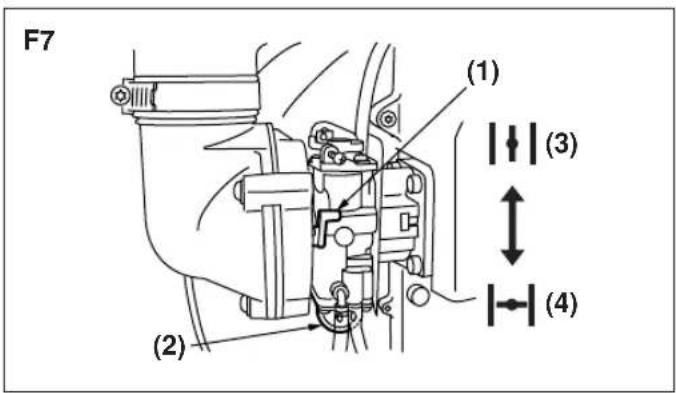
Push the primer bulb until fuel flows out in the clear tube. (F7)
- When the engine is cool, close the choke. (F7)
(1) Choke Lever
(2) Primer Bulb
(3) OPEN
(4)CLOSE
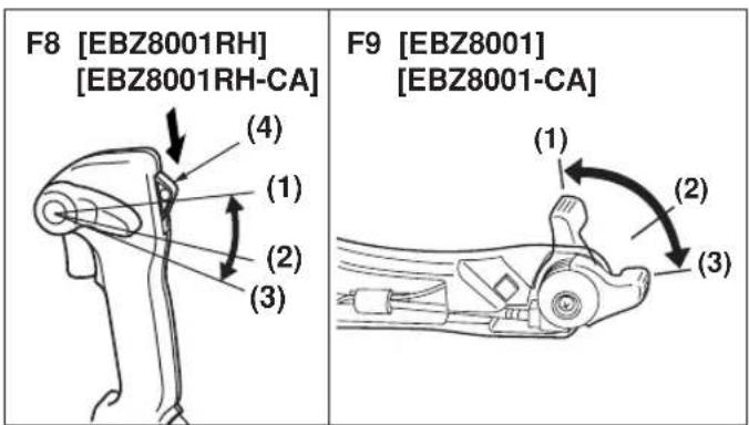
- [EBZ8001RH] [EBZ8001RH-CA] Set the ignition switch to the start position. (F8)
- Set the throttle lever in about 1/3 open position. (F8)(F9)
(1) Full Throttle
(2) About 1/3 Open
(3) Idling
(4) Ignition Switch
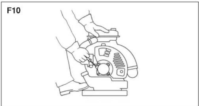
- To start, hold the top of the blower firmly with your left hand. Pull the starter knob slowly until you feel it engage and then give it a vigorous strong pull. (F10)
0
IMPORTANT
- Avoid pulling the starter rope out to its full extent and allowing the starter rope to snap back. This will prevent premature damage to the starter.
- Do not let a person stand near the blower or the
Français
- Once the engine is running, gradually open the choke if it was set closed, and let the engine run at idle speed for a minute to warm it up.

When the engine fails to start after several attempts due to overchoking, open the choke and repeat pulling the rope.
F11
F12 [EBZ8001] [EBZ8001-CA]
F13 [EBZ8001RH] [EBZ8001RH-CA]
F14
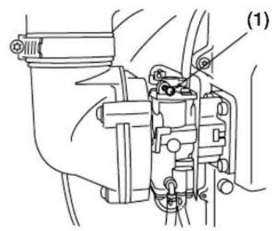
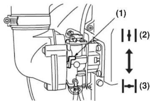
ADJUSTING IDLE SPEED (F11)
- The idling speed is set for 2000 rpm at the factory. If it is necessary to adjust the idle speed, use the adjustment screw on the top side of carburetor.
(1) Idling Adjustment Screw
STOPPING ENGINE
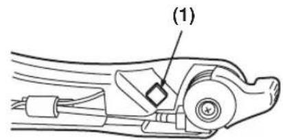
[EBZ8001] [EBZ8001-CA]
- Move the throttle lever to the idling position and press the stop switch (red button). The machine has the mechanism that once the stop button is pushed the plug won't give off sparks until the engine stops. (F12)
(1) Stop Switch
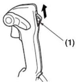
[EBZ8001RH] [EBZ8001RH-CA]
- Move the throttle lever to the idling position and set the ignition switch to the stop position. (F13)
(1) Ignition Switch

If the engine won't stop when setting the ignition switch to the stop position, close the choke lever and stop the engine.
In this case, please repair the machine at your nealest servicing dealer. (F14)
(1) Choke Lever
(2) OPEN
(3) CLOSE
Français
[EBZ8001] [EBZ8001-CA]
[EBZ8001] [EBZ8001-CA]
Maintenance, replacement, or repair of the emission control device and systems may be performed by any non-road engine repair establishment or individual.
| System/Component Procedure or 25 hours 50 hours 100 hours | Daily Every Every Every Before use after after after | ||||
| Air Filter Inspection | ✓ | ||||
| Paper Filter | Inspect/Replace | ✓ | |||
| Fuel Leaks Inspect/Replace | ✓ | ||||
| Fuel Filter Inspect/Replace | ✓ | ✓ | |||
| Fuel Line Inspect/Clean | ✓ | ||||
| Spark Plug Inspect/Clean | ✓ | ||||
| Muffler Inspect/Clean | ✓ | ||||
| Muffler Spark Arrester Inspect/Clean | ✓ | ||||
| Cooling System | Inspect/Clean | ✓ | |||
| Screws/Nuts/Bolts | Tighten | ✓ | |||
| Cylinder Exhaust Port | Inspect/Clean | ✓ | |||

WARNING
Make sure that the engine has stopped and is cool before performing any service to the blower. Contact with rotating blower fan or hot muffler may result in a personal injury.
AIR CLEANER
- Never operate the blower without an air filter or with a deformed or broken filter element because unfiltered dusty air will quickly ruin the engine.
- Check the air cleaner before use.
A clogged air filter may increase fuel consumption while cutting down the engine power.
- Never clean a paper filter by striking it with or against another object. The filter may be damaged and resultant dust contamination can diminish engine performance.
Français
9. Entretien
CLEANING AIR FILTER:
- Unscrew 2 knob bolts and remove the air cleaner cover. Then remove a prefilter mounted inside the air cleaner cover.
(1) Knob Bolt
(2) Prefilter
(3) Inner Case
(4) Paper Filter
- Wash the prefilter in fresh, non flammable cleaning solution (ex. warm soapy water) and then dry. (Clean the air filter once in a week.)
- Exchange the paper filter element with new one in case it has been contaminated.
WARNING
- This prefilter is dry type.
- Never wash the prefilter in oleaginous cleaning solution.
- Do not clean a paper filter by striking it.
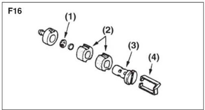
FUEL FILTER
- A clogged fuel filter may cause poor acceleration of the engine. Check periodically to see if the filter is clogged with dirt. The filter can be taken out of the fueling port using a small wire hook. Disconnect the filter assembly from the fuel pipe and unhook the retainer to disassemble it. Clean the components with gasoline.
(1) Screen
(2) Element
(3) Holder
(4) Retainer
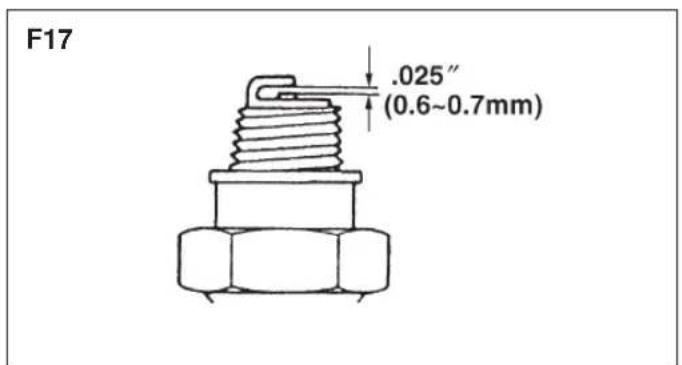
SPARK PLUG
- The spark plug may gather carbon deposits on its firing end with reasonable use. Remove and inspect the spark plug every 25 hours and clean the electrodes as necessary with a wire brush. The spark gap should be adjusted to .025 in (0.6 0.7mm)
- Plug manufacturers recommend replacing the plug twice a year to avoid unexpected plug failure in a job. REPLACEMENT PLUG IS A NGK CMR7H.
Français
9. Entretien 9. Mantenimiento
(1)Grille
(2) Element
(3) Support
(4) Retenue
■ BOUGIE
Note that using any spark plugs other than those designated may result in the engine failing to operate properly or in the engine becoming overheated and damaged.
- To install the spark plug, first turn the plug until it is finger tight, then tighten it a quarter turn more with a socket wrench.
MUFFLER

WARNING
- Inspect periodically, the muffler for loose fasteners, any damage or corrosion. If any sign of exhaust leakage is found, do not use the blower and have it repaired immediately.
Note that failing to do so may result in the engine catching on fire.

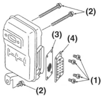
IMPORTANT
- Before starting operation, always make sure to check if the muffler is properly held by three bolts (F18 (2)). (Fastening Torque: 8 to 12N· m )
- Also make sure that the speak arrester and the diffuser are properly attached with four bolts (F18 (1)). (Fastening Torque : 2 to 3 N·m)
- Even if one of seven bolts is loose, it may result in engine catching on fire.
(1) Bolt
(2) Bolt
(3) Spark arrester
(4) Diffuser
SPARK ARRESTER
- The muffler is equipped with a spark arrester to prevent red hot carbon from flying out of the exhaust outlet. Periodically inspect and clean as necessary with a wire brush. In the State of California it is required by law (Section 4442 of the California Pulic Resources Code) to equip a spark arrester when a gas powered tool is used in any forest covered, bush covered, or grass covered unimproved land.
F18
9. Entretien 9. Mantenimiento
IMPORTANT
- Remove the muffler, insert a screwdriver into the vent, and wipe away any carbon buildup. Wipe away any carbon buildup on the muffler exhaust vent and cylinder exhaust port at the same time.
- Tighten all screws, bolts, and fittings.
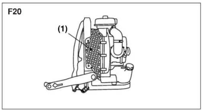
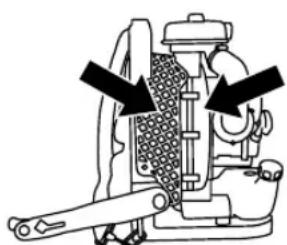
AIR INLET NET
0IMPORTANT
- Blowing air is taken in from the air inlet net. When air flow has dropped down during operation, stop the engine and inspect the air inlet net for blocking by obstacles.
- Note that failure to remove any such obstacles may result in the engine becoming overheated and damaged.
(1) Net
WARNING
Never use the blower without the net of the blower. Before each use, check that the net is attached in place and is free from any damage.
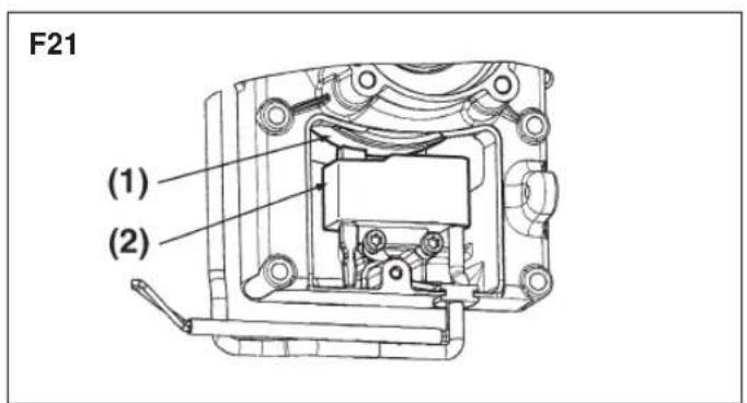
■ IGNITION COIL AIR GAP INSPECTION
- If the gap is out of standard or when installing the coil or rotor, adjust the air gap between the ignition coil and the iron core of the rotor.
Air Gap:
0.40mm (0.35 ~ 0.45mm)
0.016" (0.014 ~ 0.017")
(1) Rotor
(2) Ignition coil
Français
9. Entretien 9. Mantenimiento
■ ACTIONS DEVANT ÉTRE ENTREPRISES TOUTES LES 100 HEURES D'UTILISATION
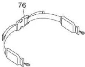
- If the shoulder strap is damaged it may break during use, thus causing the product to fall and resulting in personal injury. Follow the instructions below to replace the shoulder strap with new one.
Take off the clip from the strap.
Pass the end of the strap through the hanger.
- Return the clip to the strap.
(1)Clip

IMPORTANT
Make sure that the thick round bar of the clip is in the strap.
If it is attached in the wrong way, it leads to serious personal injury.

IMPORTANT
Do not apply liquid type screw lock glue on screws or bolts used to fix plastics components. Adherence of this type of glue may cause cracks on plastics and end up with the breakage.
English
10. Storage
BEFORE STORING THE BLOWER:
- Drain a fuel tank and push the primer bulb until it becomes empty of fuel.
- Remove the spark plug and drop a spoonful of 2-cycle oil into the cylinder. Crank the engine several time and install the spark plug.
- Store unit in a dry, dust free place, out of the reach of children.
English
11. Disposal
- When disposing your machine, fuel or oil for the machine, be sure to allow your local regulations.
Français
9. Entretien 9. Mantenimiento
COUROIE DE DÉCHARGE
Case 1. Starting failure
| CHECK PROBABLE CAUSES ACTION |
| fuel tank → incorrect fuel → drain it and with correct fuel |
| fuel filter → fuel filter is clogged → clean |
| carburetor adjustment screw → out of normal range → adjust to normal range |
| sparking (no spark) → spark plug is fouled/wet → clean/dry |
| → plug gap is incorrect → correct (GAP: 0.6 - 0.7 mm) |
| spark plug → disconnected → retighten |
Case 2. Engine starts but does not keep running/Hard re-starting.
| CHECK PROBABLE CAUSES ACTION | |||
| fuel tank | → | incorrect fuel or staled fuel | → drain it and with correct fuel |
| carburetor adjustment screw | → | out of normal range | → adjust to normal range |
| muffler,cylinder (exhaust port) | → | carbon is built-up | → wipe away |
| air cleaner | → | clogged with dust | → wash |
| cylinder fin, fan cover | → | clogged with dust | → clean |
When your unit seems to need further service, please consult with our service shop in your area.
1.Use RedMax/ZENOAH genuine parts as specified in the parts list for repair and/or replacement.
2. RedMax/ZENOAH does not warrant the machines, which have been damaged by the use of any parts other than those specified by the company.
3. When placing parts orders for repair and/or replacement, check if the model name and the serial number are applicable to those specified in the parts list, then use parts number described in the parts list.
4. The contents described in the parts list may change due to improvement.
5. The parts for the machine shall be supplied seven (7) years after the machine is discontinued. [It is possible that some specific parts may be subject to change of their delivery term and list price within the limit of seven (7) years after the machine is discontinued. It is also possible that some parts may be available even after the limit of seven (7) years.]
REMARQUE:
APPLICABLE SERIAL NUMBERS :
EBZ8001:61206884 and up
EBZ8001RH : 61201408 and up
EBZ8001-CA:70400101 and up
EBZ8001RH-CA:70400101 and up
NUMEROS DE SERIES APPLICABLES :
(EBZ8001:S/N61206884andup)
(EBZ8001RH : S/N 61201408 and up)
(EBZ8001-CA : S/N 70400101 and up)
(EBZ8001RH-CA : S/N 70400101 and up)
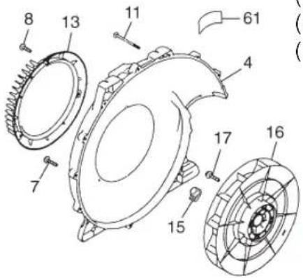
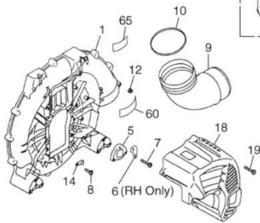
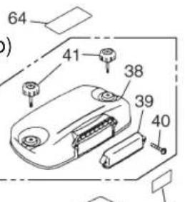
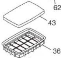
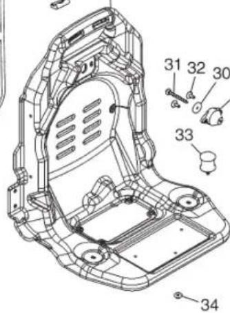
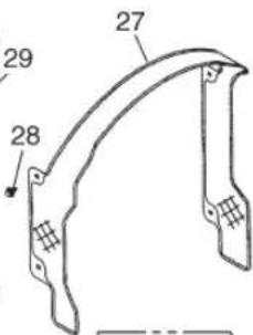
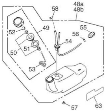
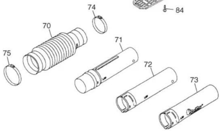
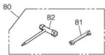
Fig.1 BLOWER GROUP
EBZ8001/EBZ8001RH/EBZ8001-CA/EBZ8001RH-CA
Fig.1 BLOWER GROUP
(EBZ8001 : S/N 61206884 and up) (EBZ8001-CA : S/N 70400101 and up)
(EBZ8001RH : S/N 61201408 and up) (EBZ8001RH-CA : S/N 70400101 and up)
| Key# | Part Number Description Q'ty | |
| 1 | 848-L58-55A4 VOLUTE CASE 1 | |
| 4 | 848-L58-55Z0 VOLUTE COVER 1 | |
| 5 | 848-L58-55G0 BRACKET 2 | |
| 6 | 2750-72230 CLAMP (RH Only) 1 | |
| 7 | T4970-52510 SCREW TORX 17 | |
| 8 | T4970-51410 SCREW TORX 4 | |
| 9 | 848-L58-55C1 ELBOW | 1 |
| 10 | 07000-12100 O-RING | 1 |
| 11 | T4960-57030 SCREW TORX 2 | |
| 12 | 3310-53331 NUT | 2 |
| 13 | 848-L58-55D4 COVER INLET | 1 |
| 14 | 848-8K4-0010 CLAMP | 1 |
| 15 | 848-L58-55J0 CAP | 1 |
| 16 | 848-L59-52A0 FAN | 1 |
| 17 | 848-816-3500 BOLT TORX | 4 |
| 18 | 848-L58-31A3 ENGINE COVER | 1 |
| 19 | T4970-52510 SCREW TORX 4 | |
| 20 | 848-L5M-3502 FRAME ASSY | 1 |
| 21 | 848-L5M-35A0 • FRAME | 1 |
| 23 | 848-L58-3613 • BAND ASSY | 2 |
| 24 | 848-L58-36C1 • CLIP | 2 |
| 25 | 848-L58-35C2 PAD | 1 |
| 26 | 3495-21320 CLIP | 6 |
| 27 | 848-L58-3521 NET COMP. | 1 |
| 28 | 1480-74710 CLIP | 4 |
| 29 | 2750-32510 DAMPER | 1 |
| 30 | 848-870-5040 WASHER | 1 |
| 31 | 848-815-4000 BOLT TORX | 1 |
| 32 | T4960-51631 SCREW TORX 2 | |
| 33 | 2750-32610 DAMPER | 2 |
| 34 | 2750-32620 NUT (M6) | 2 |
| 35 | 848-L58-83A2 BODY, CLEANER | 1 |
| 36 | 848-L58-83U2 CASE, INNER | 1 |
| 37 | 848-L58-8322 COVER ASSY | 1 |
| 38 | - • COVER | 1 |
| 39 | T4012-82220 • COVER | 1 |
| 40 | T4970-52510 • SCREW TORX 2 | |
| 41 | 848-L58-83J1 • KNOB BOLT | 2 |
| 42 | T4012-82311 ELEMENT 1 | |
| 43 | T4012-82321 ELEMENT 1 | |
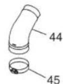
| 44 | 848-L58-83P2 HOSE | 1 |
| 45 | 848-8K4-0000 CLAMP | 2 |
| 46 | T4950-52030 BOLT TORX | 4 |
| 47 | 848-864-5000 NUT | 4 |
| Key# | Part Number Description | ||
| 48a | 848-L58-8511 TANK ASSY 1 | ||
| 48b | 848-L60-8500 TANK ASSY (CA only) 1 | ||
| 49 | 848-L23-8510 CAP ASSY 1 | ||
| 50 | 4500-85300 · · HOLDER ASSY 1 | ||
| 51 | 4500-85220 · · PACKING 1 | ||
| 52 | 5601-85260 · · FILTER 1 | ||
| 53 | 848-L23-85N0 · · STOPPER 1 | ||
| 54 | 848-L58-8530 · · PIPE COMP. 1 | ||
| 55 | 3302-85400 · FILTER 1 | ||
| 56 | 1260-85460 · CLIP 1 | ||
| 57 | T4960-51231 SCREW TORX 3 | ||
| 58 | 1950-86120 CLIP 1 | ||
| 60 | 2750-31911 LABEL, CAUTION 1 | ||
| 61 | T4012-32610 LABEL, NET 1 | ||
| 62 | 848-L5M-90R0 LABEL, EBZ8001 1 | ||
| 63 | 848-L5M-90S0 LABEL 1 | ||
| 64 | T4012-82280 LABEL 1 | ||
| 65 | 848-8X5-0770 LABEL, SOUND 1 | ||
| 70 | 848-L58-65A1 HOSE 1 | ||
| 71 | 848-L58-6510 SWIVEL JOINT 1 | ||
| 72 | 848-L58-65D0 PIPE, STRAIGHT 1 | ||
| 73 | 848-L58-65E1 PIPE, END 1 | ||
| 74 | 848-8K4-0020 CLAMP 1 | ||
| 75 | 848-8K4-0030 CLAMP 1 | ||
| 76 | 848-L58-3621 BAND ASSY Acc | ||
| 80 | 848-8U0-0020 TOOL-SET 1 | ||
| 81 | 3540-91120 · SPANNER 1 | ||
| 82 | 848-8U1-0020 · SOCKET 1 | ||
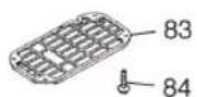
| 83 | 848-L58-35S0 NET 1 | ||
| 84 | 848-8K3-0030 CLIP 1 | ||
(EBZ8001: S/N 61206884 and up)
(EBZ8001RH : S/N 61201408 and up)
(EBZ8001-CA:S/N 70400101 and up)
(EBZ8001RH-CA : S/N 70400101 and up)
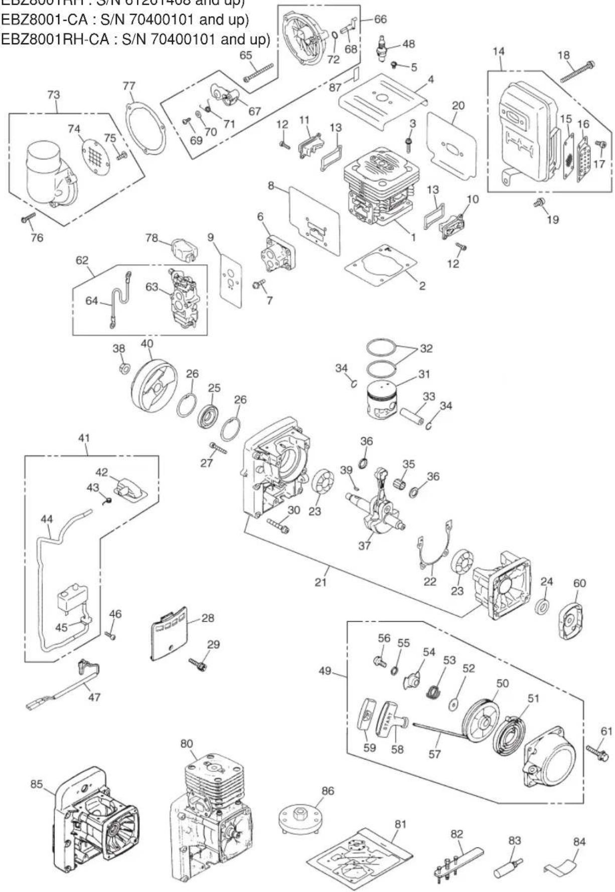
Fig.2 ENGINE GROUP
EBZ8001/EBZ8001RH/EBZ8001-CA/EBZ8001RH-CA
Fig.2 ENGINE GROUP
(EBZ8001 : S/N 61206884 and up) (EBZ8001-CA : S/N 70400101 and up)
(EBZ8001RH : S/N 61201408 and up) (EBZ8001RH-CA : S/N 70400101 and up)
| Key# | Part Number Description | Description Q'ty |
| 1 | 848-H00-12A3 CYLINDER 1 | |
| 2 | 848-H00-12B1 GASKET, BASE 1 | |
| 3 | 4820-12130 BOLT TORX 4 | |
| 4 | 848-H00-12G0 PLATE, CYL 1 | |
| 5 | T4960-50810 SCREW TORX 2 | |
| 6 | 848-H00-14A0 INSULATOR 1 | |
| 7 | 848-815-2002 BOLT TORX 4 | |
| 8 | 848-H00-14B2 GASKET, INSU 1 | |
| 9 | 848-H00-14C1 GASKET, CARB 1 | |
| 10 | 848-H00-12C0 COVER, TR-S 1 | |
| 11 | 848-H00-12D0 COVER, TR-F 1 | |
| 12 | 4820-72150 BOLT TORX 4 | |
| 13 | 848-H00-12E1 GASKET TR 2 | |
| 14 | 848-H10-1510 MUFFLER ASSY 1 | |
| 15 | 848-H10-15B0 • ARRESTER 1 | |
| 16 | 848-H10-15U0 • DIFFUSER 1 | |
| 17 | T4950-40800 • BOLT 4 | |
| 18 | 848-816-7500 BOLT TORX 2 | |
| 19 | T4950-61431 BOLT TORX 1 | |
| 20 | 848-H00-15C1 GASKET, MUFFLER 1 | |
| 21 | 848-H00-2110 CRANKCASE COMP. 1 | |
| 22 | 848-H00-21D1 GASKET, CASE 1 | |
| 23 | 848-89G-4200 BEARING 2 | |
| 24 | 848-8AG-2700 SEAL 1 | |
| 25 | 848-8AG-4200 SEAL 1 | |
| 26 | 04065-04218 SNAP RING 2 | |
| 27 | 4820-21310 BOLT TORX 4 | |
| 28 | 848-H00-21H0 COVER 1 | |
| 29 | 4820-72150 BOLT TORX 1 | |
| 30 | 848-816-4500 BOLT TORX 6 | |
| 31 | 848-H00-41A1 PISTON 1 | |
| 32 | 848-8C5-0200 RING 2 | |
| 33 | 848-8BC-4500 PIN 1 | |
| 34 | 848-8T3-1300 SNAP RING 2 | |
| 35 | 848-88C-1600 BEARING 1 | |
| 36 | 848-873-C000 WASHER 2 | |
| 37 | 848-H00-4203 CRANKSHAFT COMP. 1 | |
| 38 | 1400-43230 NUT 1 | |
| 39 | 1000-43240 KEY 1 | |
| 40 | 848-H10-71A0 ROTOR 1 | |
| 41 | 848-H10-7121 COIL ASSY 1 | |
| 42 | T1108-72110 • CAP 1 | |
| 43 | T1108-72120 • SPRING 1 | |
| 44 | T1108-72130 • TUBE 1 | |
| 45 | 5500-72130 • GROMMET 1 |
| Key# | Part Number Description Q'ty | |
| 46 | 4820-72150 BOLT TORX 2 | |
| 47 | T1108-71240 CORD COMP. 1 | |
| 48 | 3699-91867 SPARKPLUG 1 | |
| 49 | 848-H00-7512 RECOIL ASSY 1 | |
| 50 | 848-H00-75C2 • REEL 1 | |
| 51 | 848-H00-75B0 • SPRING 1 | |
| 52 | 848-H00-75M1 • WASHER 1 | |
| 53 | 848-H00-75L2 • SPRING FRICTION 1 | |
| 54 | 848-H00-75K2 • PLATE FRICTION 1 | |
| 55 | 848-H00-75W1 • WASHER 1 | |
| 56 | 4500-75150 • SCREW 1 | |
| 57 | 848-8S9-0000 • ROPE 1 | |
| 58 | 848-H00-75J0 • KNOB 1 | |
| 59 | 848-H00-75Z0 • KNOB CAP 1 | |
| 60 | 848-H00-7521 PULLEY ASSY 1 | |
| 61 | 4820-32120 BOLT TORX 4 | |
| 62 | 848-H00-8000 CARBURETOR SET 1 | |
| 63 | 848-H00-8100 • CARBURETOR ASSY 1 | |
| 64 | 848-8M1-0550 • CORD 1 | |
| 65 | 4820-82310 BOLT TORX 2 | |
| 66 | 848-H01-8330 CUP ASSY 1 | |
| 67 | 848-H01-83C0 • PLATE, CHOKE 1 | |
| 68 | 848-H01-83D0 • LEVER 1 | |
| 69 | 848-854-1600 • SCREW 1 | |
| 70 | 848-870-4000 • WASHER 1 | |
| 71 | 848-H00-84A0 • SPRING 1 | |
| 72 | 07000-11007 • O-RING 1 | |
| 73 | 848-H00-8341 COVER ASSY 1 | |
| 74 | 848-H00-83K1 • SCREEN 1 | |
| 75 | 1491-82360 • SCREW 2 | |
| 76 | T4970-52510 SCREW TORX 3 | |
| 77 | 848-H00-83M1 GASKET, CUP 1 | |
| 78 | 4500-81910 COVER 1 | |
| 80 | 848-H00-1000 SHORT BLOCK Acc | |
| 81 | 848-H00-0610 GASKET KIT Acc | |
| 82 | 2750-96100 PULLER ASSY Acc | |
| 83 | 4810-96220 STOPPER Acc | |
| 84 | 848-8W4-0050 GAUGE Acc | |
| 85 | 848-H00-2100 CASE ASSY (with BAG) Acc | |
| 86 | 848-8W0-0020 PULLER Acc | |
| 87 | T1108-82061 LABEL, CHOKE 1 |
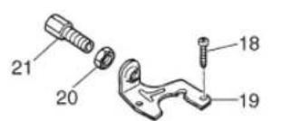
Fig.3 CARBURETOR COMPONENTS
(EBZ8001: S/N 61206884 and up)
(EBZ8001RH : S/N 61201408 and up)
(EBZ8001-CA:S/N 70400101 and up)
(EBZ8001RH-CA:S/N 70400101 and up)
CARBURETOR ASSY (WYA-44)
P/NO.848-H00-8100
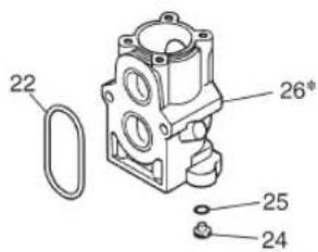
| Key# | Part Number Description Q'ty | ||
| 1 T | 1108-81450 BODY | DY ASSY 1 | |
| 2 | - | SCREEN 1 | |
| 3 | - | VALVE 1 | |
| 4 | - | SPRING 1 | |
| 5 | - | SCREW 1 | |
| 6 | - | P I N | |
| 7 | - | LEVER 1 | |
| 8 | 1850-81490 BODY 1 | ||
| 9 | 1850-81520 COVER 1 | ||
| 10 | 1751-81510 PUMP | 1 | |
| 11 | 5500-81160 WASHER | 1 | |
| 12 | 1881-81140 SWIVEL | 1 | |
| 13 | 1751-81130 RING | 1 | |
| 14 | 4810-81410 GASKET | 1 | |
| 15 | 1065-81420 DIAPHRAGM | 1 | |
| 16 | 1850-81470 GASKET | 1 | |
| 17 | 4810-81260 DIAPHRAGM | 1 | |
| 18 | 1752-81110 SCREW 2 | ||
| Key# | Part Number Description | ||
| 19 5 | 500-81120 BRACKET 1 | ||
| 20 1 | 751-81180 NUT 1 | ||
| 21 1 | 918-81170 SCREW 1 | ||
| 22 | 848-H00-80A0 RING, PACKING 1 | ||
| 23 1 | 850-81530 SCREW 4 | ||
| 24 2 | 750-81250 JET #59.0 1 | ||
| 25 1 | 751-81240 O-RING 1 | ||
| 26* | - | BODY | 1 |
| 27* | - | VALVE ASSY | 1 |
[NOTE]
26*-BODY and 27*-VALVE ASSY are not supplied as an individual part respectively, but supplied as a CARBURETOR ASSY (P/NO.848-H00-8100).
(EBZ8001 : S/N 61206884 and up)
(EBZ8001-CA : S/N 70400101 and up)
![RedMax EBX8001CA - [NOTE] - 1](/content/2026/02/419761/images/0f57f13703e4f1939f634f1a3e230789de6eddb6cb66fa60a3b596107e26d38c.jpg)
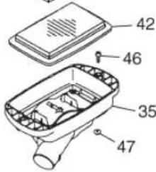
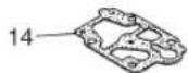
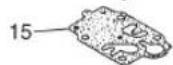
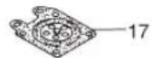
Fig.4 LEVER SET
![RedMax EBX8001CA - [NOTE] - 2](/content/2026/02/419761/images/38b45f91043aa66aa5638501d45d40a3f40cb84168cdc9777577ac575dbd8578.jpg)
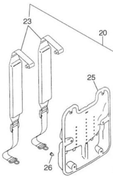
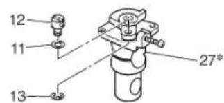
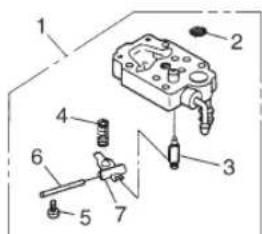
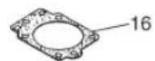
Fig.5 LEVER (R) SET
| Key# | Part Number Description Q'ty | |
| 1 | 848-L58-3301 LEVER SET 1 | |
| 2 | T4012-25100 • LEVER 1 | |
| 3 | 3310-53331 • NUT 1 | |
| 4 | 01642-20508 • WASHER 1 | |
| 5 | T4012-25211 • ARM 1 | |
| 6 | T4012-25311 • BRACKET 1 | |
| 7 | 3495-25410 • BOLT 1 | |
| 8 | 3495-25420 • SPRING 1 | |
| 9 | 3495-25440 • WASHER 1 | |
| 10 | 01584-00605 • NUT 1 | |
| 11 | 3495-25450 • WASHER 2 | |
| 12 | 848-L53-72A2 • SWITCH 1 | |
| 13 | 1601-72411 • CAP 1 | |
| 14 | T4012-83110 • CABLE COMP. 1 | |
| 15 | 848-8H1-3052 • TUBE 1 | |
| 16 | 848-L58-6521 GRIP ASSY 1 | |
| 17 | 2750-51520 • WING BOLT 1 | |
| 18 | 3495-51430 • WING NUT 1 | |
| 19 | 3238-15230 • WASHER 2 | |
| 20 | 2750-51540 • NUT 1 | |
| 21a | 848-L5M-90C1 LABEL, RECOIL 1 | |
| 21b | 848-L60-90C0 LABEL, RECOIL (CA only) 1 | |
| 22 | T4960-51631 SCREW TORX 2 |
(EBZ8001RH : S/N 61201408 and up)
EBZ8001RH-CA : S/N 70400101 and up)
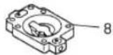
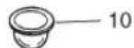
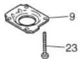
![RedMax EBX8001CA - [NOTE] - 3](/content/2026/02/419761/images/146032b6520c64cd92ce628c1a9d7225e3421dc3d28ea3357a12218e7a768d6d.jpg)
![RedMax EBX8001CA - [NOTE] - 4](/content/2026/02/419761/images/9e26a58cc12cb50e3dfd4a3a16cd967116ab13d0ed3550887de9595225f52adc.jpg)
Key# Part Number Description Q'ty
| 1 | 848-L59-3411 LEVER (R) SET | 1 |
| 2 | 848-L59-34B0 • COVER | 1 |
| 3 | 848-L59-34A0 • CASE | 1 |
| 4 | T4023-25310 • SCREW 4x14 | 5 |
| 5 | T4023-25410 • LEVER, throttle | 1 |
| 6 | 848-L54-34D1 • LEVER 1 | |
| 7 | T4023-25440 • SHAFT 1 | |
| 8 | T4023-25450 • WASHER 1 | |
| 9 | T4023-25460 • SPRING WASHER | 1 |
| 10 | 3238-15230 • WASHER 1 | |
| 11 | T4023-25480 • CLIP 1 | |
| 12 | T4023-25710 • SWITCH 1 | |
| 13 | T4023-25721 • SPRING 1 | |
| 14 | T4023-25730 • SCREW 4x10 | 1 |
| 15 | T4023-25740 • CORD | 1 |
| 16 | T4023-25750 • CORD | 1 |
| 17 | 848-8P0-0190 • CABLE 1 | |
| 18 | 848-8H1-9402 • TUBE | 1 |
| 19 | 3495-51420 • WING BOLT | 1 |
| 20 | 2750-51540 • NUT 1 | |
| 21 | 848-L59-65G0 CLAMP | 1 |
| 22a | 848-L5M-90C1 LABEL, RECOIL | 1 |
| 22b | 848-L60-90C0 | LABEL, RECOIL (CA only) |
CALIFORNIA EMISSION CONTROL WARRANTY STATEMENT YOUR WARRANTY RIGHTS AND OBLIGATIONS
The California Air Resources Board and ZENOAH AMERICA, INC. are pleased to explain the emission control system warranty on your 2007 and later small off-road engine. In California, new small off-road engines must be designed, built and equipped to meet the state's stringent anti-smog standards. ZENOAH AMERICA, INC. must warrant the emission control system on your small off-road engine for the periods of time listed below provided there has been no abuse, neglect or improper maintenance of your small off-road engine.
Your emission control system may include parts such as the carburetor, fuel tank and the ignition system.
Where a warrantable condition exists, ZENOAH AMERICA, INC. will repair your small off-road engine at no cost to you including diagnosis, parts and labor.
Manufacturer's warranty coverage:
The 2007 and later small off-road engines are warranted for two years. If any emission-related part on your engine is defective, the part will be repaired or replaced by ZENOAH AMERICA, INC.
Owner's warranty responsibilities:
-
As the small off-road engine owner, you are responsible for the performance of the required maintenance listed in your owner's manual. ZENOAH AMERICA, INC. recommends that you retain all receipts covering maintenance on your small off-road engine, but ZENOAH AMERICA, INC. can not deny warranty solely for the lack of receipts or for your failure to ensure the performance of all scheduled maintenance.
-
As the small off-road engine owner, you should however, be aware that ZENOAH AMERICA, INC. may deny you warranty coverage if your small off-road engine or a part has failed due to abuse, neglect, improper maintenance or unapproved modification.
-
You are responsible for presenting your small off-road engine to a ZENOAH AMERICA, INC. distribution center as soon as a problem exists. The warranty repairs should be completed in a reasonable amount of time, not to exceed 30 days.
If you have any questions regarding your warranty rights and responsibilities, you should contact ZENOAH AMERICA, INC. at (770)-381-5147 or you can write to
ZENOAH AMERICA, INC.
1100 Laval Blvd. Suite 110
Lawrenceville, Georgia 30043
ENONCE DE GARANTIE DE CONTROLE DES EMISSIONS DE CALIFORNIE VOS DROITS ET OBLIGATIONS DE GARANTIE
THE CARBURETOR ASSEMBLY, COIL ASSEMBLY, ROTOR, SPARKPLUG, AIR FILTER, FUEL FILTER, INTAKE MANIFOLD, AND THE GASKETS
ALL OTHER PARTS EXCEPT ABOVE PARTS, FOR TWO (2) YEARS OF HOME USE, TWO (2) YEARS FOR COMMERCIAL USE AND NINETY (90) DAYS FOR RENTAL USE FROM THE DATE OF ORIGINAL PURCHASE, THE COMPANY, THROUGH ANY RedMax DEALER, WILL REPAIR OR REPLACE, FREE OF CHARGE, FOR THE ORIGINAL PURCHASER, ANY PART OF PARTS FOUND TO BE DEFECTIVE IN MATERIAL AND/OR WORKMANSHIP. THIS IS THE EXCLUSIVE REMEDY.
THE PURCHASER SHALL BEAR COSTS OF TRANSPORTING THE UNIT TO AND FROM THE RedMax DEALER.
THE PURCHASER SHALL NOT BE CHARGED FOR DIAGNOSTIC LABOR WHICH LEADS TO THE DETERMINATION THAT A WARRANTED PART IS DEFECTIVE, IF THE DIAGNOSTIC WORK IS PERFORMED AT THE RedMax DEALER.
THE PURCHASER OR OWNER IS RESPONSIBLE FOR THE PERFORMANCE OF THE REQUIRED MAINTENANCE AS DEFINED BY THE MANUFACTURER IN THE OWNER/OPERATOR MANUAL.
ANY WARRANTED PART WHICH IS NOT SCHEDULED FOR REPLACEMENT AS REQUIRED MAINTENANCE, OR WHICH IS SCHEDULED ONLY FOR REGULAR INSPECTION TO THE EFFECT OF "REPAIR OR REPLACE AS NECESSARY" SHALL BE WARRANTED FOR THE WARRANTY PERIOD. ANY WARRANTED PART WHICH IS SCHEDULED FOR REPLACEMENT AS REQUIRED MAINTENANCE SHALL BE WARRANTED FOR THE PERIOD OF TIME UP TO THE FIRST SCHEDULED REPLACEMENT POINT FOR THE PART.
ANY REPLACEMENT PART THAT IS EQUIVALENT IN PERFORMANCE AND DURABILITY MAY BE USED IN NON-WARRANTY MAINTENANCE OR REPAIRS, AND SHALL NOT REDUCE THE WARRANTY OBLIGATION OF THE COMPANY.
THE COMPANY IS LIABLE FOR DAMAGES TO OTHER ENGINE COMPONENTS CAUSED BY THE FAILURE OF A WARRANTED PART STILL UNDER WARRANTY.
THE WARRANTY DOES NOT APPLY TO THOSE UNITS WHICH HAVE BEEN DAMAGED BY NEGLIGENCE OF INSTRUCTION LISTED IN THE OWNER/OPERATOR MANUAL FOR PROPER USE AND MAINTENANCE OF THE UNITS, ACCIDENTAL MISHANDLING, ALTERATION, ABUSE, IMPROPER LUBRICATION, USE OF ANY PARTS OR ACCESSORIES, OTHER THAN THOSE SPECIFIED BY THE COMPANY, OR OTHER CAUSES BEYOND THE COMPANY'S CONTROL.
THIS WARRANTY DOES NOT COVER THOSE PARTS REPLACED BY NORMAL WEAR OR HARMLESS CHANGES IN THEIR APPEARANCE.
THERE ARE NO OTHER EXPRESS WARRANTY.
IMPLIED WARRANTYIS INCLUDING THOSE OF MERCHANTABILITY AND FITNESS FOR A PARTICULAR PURPOSE ARE LIMITED TO TWO (2) YEARS OF HOME USE, TWO (2) YEARS FOR COMMERCIAL USE AND NINETY (90) DAYS FOR RENTAL USE FROM THE ORIGINAL DELIVERY DATE.
LIABILITIES FOR INCIDENTAL OR CONSEQUENTIAL DAMAGE UNDER ANY AND ALL WARRANTY ARE EXCLUDING.
SOME STATES DO NOT ALLOW LIMITATION ON HOW LONG AN IMPLIED WARRANTY LASTS OR EXCLUSION OR LIMITATION OF INCIDENTAL OR CONSEQUENTIAL DAMAGES, SO THE ABOVE LIMITATION OR EXCLUSION MAY NOT APPLY TO YOU.
THIS WARRANTY GIVES YOU SPECIFIC LEGAL RIGHTS, AND YOU MAY ALSO HAVE OTHER RIGHTS WHICH VARY FROM STATE TO STATE.
IF YOU NEED TO OBTAIN INFORMATION ABOUT THE NEAREST SERVICE CENTER, PLEASE CALL RedMax / ZENOAH AMERICA, INC. AT (770)-381-5147.
IMPORTANT: YOU WILL RECEIVE A WARRANTY REGISTRATION CARD AT TIME OF PURCHASE. PLEASE FILL OUT THE CARD AND SEND IT TO RedMax / ZENOAH AMERICA WITHIN SEVEN (7) DAYS. BE SURE TO KEEP A COPY FOR YOUR RECORDS.

ZENOAH AMERICA, INC.
1100 Laval Blvd. Suite 110
Lawrenceville, Georgia 30043