SX2 1200.1 - Receiver PHOENIX GOLD - Free user manual and instructions
Find the device manual for free SX2 1200.1 PHOENIX GOLD in PDF.
Frequently Asked Questions - SX2 1200.1 PHOENIX GOLD
User questions about SX2 1200.1 PHOENIX GOLD
0 question about this device. Answer the ones you know or ask your own.
Ask a new question about this device
Download the instructions for your Receiver in PDF format for free! Find your manual SX2 1200.1 - PHOENIX GOLD and take your electronic device back in hand. On this page are published all the documents necessary for the use of your device. SX2 1200.1 by PHOENIX GOLD.
USER MANUAL SX2 1200.1 PHOENIX GOLD
RMS Power Ratings listed at less than 1 % THD @ 14.4v
Number of Channels: 2
1Ω: N/A
2Ω: 200W×2
4Ω: 100W×2
4Ω: Bridged 400W x 1
Total RMS Power (Sum of rated power): 400W
Bridgeable: Yes
Crossover Control, Butterworth: FLAT/HP/LP
55Hz-4kHz@12dB/Oct
Includes Remote Bass and
Phase Control (RBPC) with BASS SHIFT: N/A
40Hz EQ 0-6dB boost @ 40Hz: N/A
Input Selection: Switchable Balanced/
Unbalanced
300mV-8V Unbalanced
600mV-16V Balanced
Signal Output: N/A
Signal to Noise (CEA Standard): 76.5dB
Frequency Response: 10Hz - 39kHz @ +/-3.0dB
Efficiency(Average):88%
Auto-Turn On:
Damping Factor:
Topology Class:
Heatsink Type
Cooling Type:
Operating Voltage:
Switchable Auto-Turn On:
Power Supply Type:
Onboard Thermal Management
Power Terminal:
Speaker Terminal:
Recommended Fusing:
Average Current Draw @ 14.4v Music:
Optional RMD Ready:
Tri-Light Indicators:
Green-OverVoltageWarning
Thermal Protection
Amber-DC/Short Protection
Red - Internal Fuse Blown
Dimensions (L x W x H):
Yes
Greater than 250
Class D
Extruded Aluminum
Radiation
11.0V to 16.1V
Yes
Double Tier with OTM
4 Gauge
10 Gauge
40A
9A at 4 ohm
Yes
Blue - Standard Operation
10.5"×8.5"×2"
267mm×216mm×51mm
SX2 800.4 SPECIFICATIONS
RMS Power Ratings listed at less than 1% THD @ 14.4v
Number of Channels: 4
1Ω: N/A
2Ω: 200W×4
4Ω: 150W×4
4Ω: Bridged 400W x 2
Total RMS Power (Sum of rated power): 800W
Bridgeable: Yes
Crossover Control, Linkwitz-Riley:
FLAT/HP/LP/BP
55Hz-4kHz@12dB/Oct
Includes Remote Bass and
Phase Control [RBPC] with BASS SHIFT: Yes
40Hz EQ 0-6dB boost @ 40Hz: N/A
Input Selection:
Switchable Balanced/
Unbalanced
300mV-8v Unbalanced
600mV-16v Balanced
Signal Output: N/A
Signal to Noise (CEA Standard): 81.4dB
Frequency Response: 10Hz-39kHz @ +/-3.0dB
Efficiency(Average): 88%
Auto-Turn On:
Damping Factor
Topology Class:
Heatsink Type:
Cooling Type:
Operating Voltage:
Switchable Auto-Turn On:
Power Supply Type:
Onboard Thermal Management
Power Terminal:
Speaker Terminal:
Recommended Fusing:
Average Current Draw @ 14.4v Music:
Optional RMD Ready:
Tri-Light Indicators:
Green-OverVoltageWarning
Thermal Protection
Amber-DC/Short Protection
Red - Internal Fuse Blown
Dimensions (L x W x H):
387mm×216mm×51mm
Yes
Greater than 200
Class D
Extruded Aluminum
Radiation
11.0V to 16.1V
Yes
Double Tier with OTM
4 Gauge
10 Gauge
50A
16A at 4 ohm
Yes
Blue - Standard Operation
15.25"×8.5"×2"
IMPORTANT: A power birth certificate is included for each amplifier. SX2 amplifiers are conservatively rated and will exceed their RMS power rating shown here. All RMS power ratings and measurements are at 14.4 volts with no more than 1% THD.
SPECIFICATIONS
SX2 600.1 SPECIFICATIONS
RMS Power Ratings listed at less than 1 % THD@14.4v
Number of Channels: 1
1Ω: 600W×1
2Ω: 450W×1
4Ω: 300W×1
Total RMS Power (Sum of rated power): 600W
Bridgeable: N/A
Crossover Control, Linkwitz-Riley: HP 10Hz - 120Hz (subsonic)
FLAT/LP 40Hz - 240Hz @ 24dB/Oct
Includes Remote Bass and
Phase Control (RBPC) with BASS SHIFT: Yes
40Hz EQ 0-6dB boost @ 40Hz: Yes
Input Selection: Switchable Balanced/
Unbalanced
300mV-8v Unbalanced
600mV-16v Balanced
Signal Output: 2 Channel RCA
Signal to Noise (@ CEA Standard): 85.9dB
Frequency Response: 10Hz - 250Hz @ +/-6.0dB
10Hz-39kHz-3dB LP BYPASSED
Efficiency (Average): 85%
Auto-Turn On:
Damping Factor:
MASTER/SLAVE Capable:
Topology Class:
Heatsink Type:
Cooling Type:
Operating Voltage:
Switchable Auto-Turn On:
Power Supply Type
Onboard Thermal Management
Power Terminal:
Speaker Terminal:
Recommended Fusing:
Average Current Draw @ 14.4v Music:
Optional RMD Ready:
Tri-Light Indicators:
Green - Over Voltage Waming
Yes
Greater than 200
Yes - 1200W x 1 @ 2Ω Strapped
Class D
Extruded Aluminum
Radiation
11.0V to 16.1V
Yes
Double Tier with OTM
4 Gauge
10 Gauge
60A
15A at 4 ohm
Yes
Blue - Standard Operation
Thermal Protection
SX2 1200.1 SPECIFICATIONS
RMS Power Ratings listed at less than 1 % THD @ 14.4v
Number of Channels:
1Ω: 1200W×1
2Ω: 900W×1
4Ω: 600W×1
Total RMS Power (Sum of rated power): 1200W
Bridgeable: N/A
Crossover Control, Linkwitz-Riley: HP 10Hz - 120Hz (subsonic)
LP 40Hz - 240Hz @ 24dB/Oct
Includes Remote Bass and
Phase Control (RBPC) with BASS SHIFT: Yes
40Hz EQ 0-6dB boost @ 40Hz: Yes
Input Selection: Switchable Balanced/
Unbalanced
300mV-8v Unbalanced
600mV-16v Balanced
Signal Output: 2 Channel RCA
Signal to Noise (CEA Standard): 86.3dB
Frequency Response: 11Hz - 250Hz @ +/-6.0dB
10Hz-39kHz+/-3dB LP BYPASSED
Efficiency (Average): 85%
Amber-DC/Short Protection
Red - Internal Fuse Blown
Dimensions (L x W x H):
337mm×216mm×51mm
13.25"×8.5"×2"
Auto-Turn On:
Damping Factor:
MASTER/SLAVE Capable:
Topology Class:
Heatsink Type:
Cooling Type:
Operating Voltage:
Switchable Auto-Turn On:
Power Supply Type:
Onboard Thermal Management
Power Terminal:
Speaker Terminal:
Recommended Fusing:
Average Current Draw @ 14.4v Music:
Optional RMD Ready:
Tri-Light Indicators:
Green-OverVoltageWarning
Thermal Protection
Yes
Greater than 200
Yes - 2400W x 1 @ 2Ω Strapped
Class D
Extruded Aluminum
Radiation
11.0V to 16.1V
Yes
Double Tier with OTM
4 Gauge
10 Gauge
80A
26A at 4 ohm
Yes
Blue - Standard Operation
SX2 1200.6 SPECIFICATIONS
RMS Power Ratings listed at less than 1 % THD @ 14.4v
Number of Channels: 6
1Ω: 1-4N/A,5-6250W×2
2Ω: 200W×6
4Ω: 150W×6
Bridged 4Ω: 300W x 2
Bridged 2Ω: 1-4 N/A, 5+6 500W x 1
Total RMS Power (Sum of rated power): 1300W
Bridgeable: Yes
Crossover Control, Linkwitz-Riley: FLAT/HP/LP/BP
55Hz-4kHz @ 12dB/Oct
Channels 5/6 only:
LP 45Hz -1K @ 12dB/Oct
Includes Remote Bass and
Phase Control (RBPC) with BASS SHIFT: Yes
40Hz EQ 0-6dB boost @ 40Hz: N/A
Input Selection: Switchable Balanced/
Signal to Noise (@ CEA Standard): 81.4dB
Frequency Response: 10Hz-39kHz @ +/-3.0dB
Efficiency (Average): 88%
Red - Internal Fuse Blown
Dimensions (L x W x H):
425mm x 216mm x 51mm
Amber - DC/Short Protection
16.75"×8.5"×2"
Auto-Turn On:
Damping Factor:
Topology Class:
Heatsink Type:
Cooling
Operating Voltage:
Switchable Auto-Turn On:
Power Supply Type:
Onboard Thermal Management
Power Terminal:
Speaker Terminal:
Recommended Fusing:
Average Current Draw @ 14.4v Music:
Optional RMD Ready:
Tri-Light Indicators:
Green-OverVoltageWarning
Thermal Protection
Amber - DC/Short Protection
Red - Internal Fuse Blown
Dimensions (L x W x H):
489mm x 216mm x 51mm
Yes
Greater than 200
Class D
Extruded Aluminum
Radiation
11.0V to 16.1V
Yes
Double Tier with OTM
4 Gauge
10 Gauge
70A
24A at 4 ohm
Yes
Blue - Standard Operation
19.25"×8.5"×2"
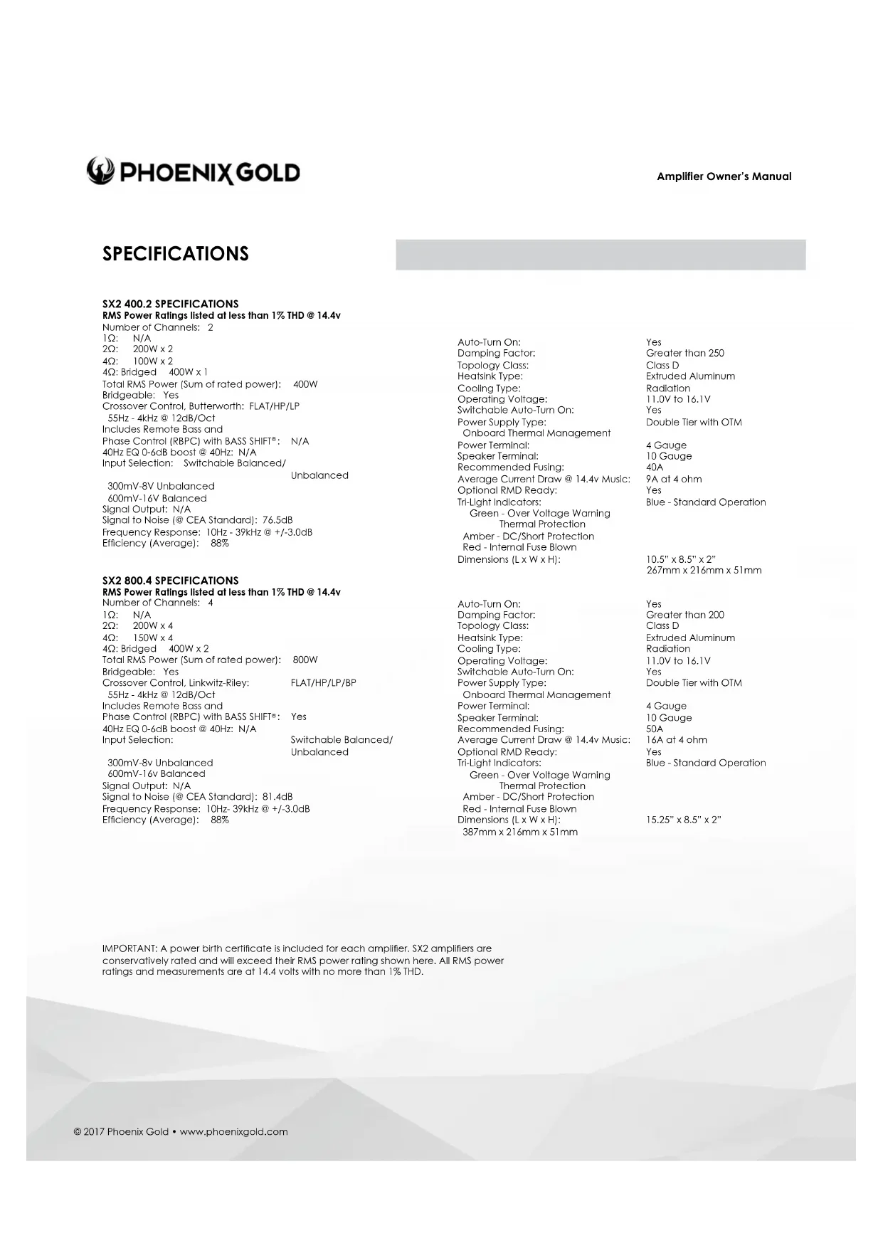
SX2 400.2
2 CHANNEL POWER AMPLIFIER

LINE IN
Connect preamp signal cables from the source unit to these terminals.
INPUTS
Select Balanced or Unbalanced inputs based on your input source's design for best S/N performance.
AUTO ON
Auto-on is useful when connecting to an OEM system that does not offer a Remote turn-on lead to activate the amplifier. When connecting directly to the amplifier using a high-level input signal the circuit can detect the input voltage (BTL <1V DC) and activate the amplifier. If your system has a standard remote turn-on lead use the standard REM input. If it is an OEM system that stays active even with the radio off (voltage on signal wires) move the switch to the OFF position and locate an alternative circuit or PAC L.O.C. PRO device to activate the amplifier. See Source Balanced/Unbalanced for High Level input wiring.
FREQ
Variable crossover frequency adjustment from 55Hz - 4kHz @ 12dB per octave.
MODE
Use in conjunction with FREQ adjustment. Selectable disabled (FLAT), Highpass (HP) or Lowpass (LP).
Select FLAT/HP/LP then adjust FREQ to desired crossover point.
LEVEL
Input sensitivity, used to properly match input signal levels from signal source and maximize amplifier output while eliminating noise. Level is not a volume control, level matching only. Adjust LEVEL to match source output voltage. For reference, a typical aftermarket radio ranges from 2v-4v of output. At minimum, use of a multi-meter and test program material is critical for this step.
SX2 400.2
RMD
RMD port is for connecting an optional Remote Monitoring Display (RMD). The RMD allows real-time viewing of system voltage.
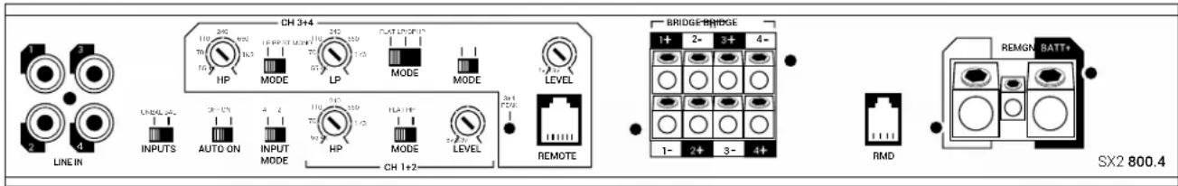
SPEAKER
Speaker connections can be configured in Stereo (Left and Right), Mono (L+R). Minimum speaker impedance is 2Ω in Stereo or 4Ω Mono. When bridging the amplifier into a Mono load, only the Left + and Right - outputs will be used. Accepts up to 10GA wire.
GND
This must be connected to the negative terminal of the car's battery or bolted to a clean, unpainted part of the vehicle's chassis.
REM
This must be connected to switched +12V usually a trigger wire coming from the head unit or ignition.
If the system does not have a standard remote turn-on, use of the AUTO ON feature may be useful.
BATT+
This must be connected to the positive terminal (+12V) of the car's battery via a 40A fuse. The fuse must be located within 18 inches of the battery. Use of 8GA or larger OFC (oxygen-free) copper wire is recommended for best performance.
TRI-LIGHT
Tri-light LED amplifier status indicators will change colors according to an array of system variables.
Blue - Standard Operation
Green - Over Voltage Warning and Thermal Protection
Amber - DC/Short Protection
Red - Internal Fuse Blown
OTM monitors amplifier internal temperatures, and if abnormal temperatures are achieved, OTM will make minor adjustments to output power to allow the amplifier to return to normal operating temperatures without interruption.
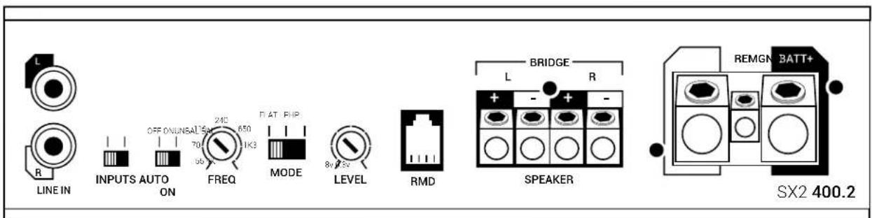
SX2 800.4
4 CHANNEL POWER AMPLIFIER
LINE IN
Connect preamp signal cables from the source unit to these terminals. Use of 2 or 4 channels of input signal selectable with INPUT MODE switch.
INPUTS
Select Balanced or Unbalanced inputs based on your input source's design for best S/N performance.
AUTO ON
Auto-on is useful when connecting to an OEM system that does not offer a Remote turn-on lead to activate the amplifier. When connecting directly to the amplifier using a high-level input signal the circuit can detect the input voltage (BTL <1v DC) and activate the amplifier. If your system has a standard remote turn-on lead use the standard REM input. If it is an OEM system that stays active even with the radio off (voltage on signal wires) move the switch to the OFF position and
locate an alternative circuit or PAC L.O.C. PRO device to activate the amplifier. See Source Balanced/Unbalanced for High Level input wiring.
INPUT MODE
Input signal selectable for 2 or 4 channels. If only 2 channels of input signal are available, select 2CH to allow signal to split to CH 3 + 4
HP1+2
Use in conjunction with MODE switch. Selectable disabled (FLAT) or Highpass (HP). If HP is selected, then adjust dial to desired crossover point, variable from 55Hz - 4kHz @ 12dB per octave.
LEVEL
Input sensitivity, used to properly match input signal levels from signal source and maximize amplifier output while eliminating noise. Level is not a volume control, level matching only. Adjust LEVEL to match source output voltage. For reference, a typical aftermarket radio ranges from 2v-4v of output. At minimum, use of a multi-meter and test program material is critical for this step. Independent level controls available for channels 1 + 2 and 3 + 4 .
SX2 800.4
CH 3+4 Controls
Use in conjunction with MODE switches. Selectable disabled (FLAT), Highpass (HP) or Bandpass (BP)/Lowpass (LP). Select FLAT/HP/LP/BP then adjust to desired crossover point, variable from 55Hz - 4kHz @ 12dB per octave. If LP or BP is desired, move both switches to LP+LP or BP+BP. If Flat or HP is selected, secondary LP/BP switch is disabled. Stereo (ST) or Mono can also be selected for channels 3+4 depending on application.
3+4 PEAK
Peak output LED indicator for channels 3+4. Helpful when used for subwoofer level adjustment. Adjust LEVEL so PEAK LED flashes when driving amplifier hard, but not so much that the LED stays on continuously. Light will illuminate when rated output voltage is achieved.
REMOTE
Selecting LP for channels 3 + 4 activates this port. This port is for connecting the (RBPC) remote bass level and phase controller with BASS SHIFT. The unique feature of the RBPC with BASS SHIFT allows for perfect adjustment of not only the subwoofer level but also 0 - 180^ of phase adjustment from the listening position. Properly adjusting phase will allow enhanced bass response, dynamics and impact at any volume. To adjust, play a test tone close to the crossover overlap you have the system adjusted to, typically in the 50 - 100Hz range. With all system speakers playing and at a moderate volume, slowly adjust the phase dial on the RBPC across the entire range. When the subwoofer is in phase with the other speakers in the system, you should be able to detect a rise in volume, "the sweet spot". Now return the control to the sweet spot and make small adjustments +/- until you maximize the output. You have now completed adjusting the phase and should not have to adjust this again. Use the level control to adjust the subwoofer output to your preference based on music program material.
SPEAKER
Speaker connections can be configured in Stereo (1 and 2 or 3 and 4), Mono (1+2 or 3+4) and 3 channel (1 and 2, 3+4). Minimum speaker impedance is 2 in Stereo or 4 Mono. When bridging the amplifier into a Mono load, only the 1+ and 2- or 3+ and 4- outputs on the bridged channels will be used. Accepts up to 10GA wire.
RMD
RMD port is for connecting an optional Remote Monitoring Display (RMD). The RMD allows real-time viewing of system voltage.
GND
This must be connected to the negative terminal of the car's battery or bolted to a clean, unpainted part of the vehicle's chassis.
REM
This must be connected to switched +12V usually a trigger wire coming from the head unit or ignition.
If the system does not have a standard remote turn-on,
use of the AUTO ON feature may be useful.
BATT+
This must be connected to the positive terminal (+12V) of the car's battery via a 50A fuse. The fuse must be located within 18 inches of the battery. Use of 8ga or larger OFC (oxygen-free) copper wire is recommended for best performance.
TRI-LIGHT
Tri-light LED amplifier status indicators will change colors according to an array of system variables.
Blue - Standard Operation
Green-Over Voltage Warning/Thermal Protection
Amber - DC/Short Protection
Red - Internal Fuse Blown
OTM monitors amplifier internal temperatures, and if abnormal
temperatures are achieved, OTM will make minor adjustments to output power to allow the amplifier to return to normal operating temperatures without interruption.
SX2 600.1
MONOBLOCK POWER AMPLIFIER

LINE IN
Connect preamp signal cables from the source unit to these terminals.
LINE OUT
Used to connect multiple amplifiers without degrading signal strength via internal line driver. Also utilized when connecting amplifiers together in a Master/Slave configuration (See Master/Slave).
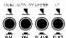
BAL/UNBAL
Select Balanced or Unbalanced inputs based on your input source's design for best S/N performance.
AUTO ON
Auto-on is useful when connecting to an OEM system that does not offer a Remote turn-on lead to activate the amplifier. When connecting directly to the amplifier using a high-level input signal the circuit can detect the input voltage (BTL <1v DC) and activate the amplifier. If your system has a standard remote turn-on lead use the standard REM input. If it is an OEM system that slays active even with the radio off (voltage on signal wires) move the switch to the OFF position and locate an alternative circuit or PAC L.O.C. PRO device to activate the amplifier. See Source Balanced/Unbalanced for High Level input wiring.
SX2 600.1
MASTER/SLAVE
Select Master if single amplifier or not connecting multiple amplifiers in either Strapped or Linked mode. Strapped mode will allow 2 SX2 600.1 amplifiers to be combined together as a single amp and drive a 2Ω load in excess of 1200 watts. Linked mode will allow any number of SX2 600.1 amplifiers to be connected to a Master SX2 600.1. Allowing all connected amplifier adjustments to be made via the Master amplifier. See diagrams for correct wiring configurations.
LP/FLAT
Select LP for subwoofer applications, will also activate REMOTE input. Select FLAT for use with external processor or for full range applications.
HP
HP adjusts a highpass crossover that can be used as a subsonic filter. Use in conjunction with LP/ FLAT switch. If LP is selected, then adjust HP dial to desired crossover point, variable from 10Hz - 120Hz @ 24dB per octave. Typically used for vented subwoofer systems and is adjusted to the port tuning frequency to prevent overdriving of the subwoofer.
PHASE
Set to 180^ on amplifier to allow adjustment from RBPC. The unique feature of the RBPC with BASS SHIFT allows for perfect adjustment of not only the subwoofer level but also 0-180° of phase adjustment from the listening position. Properly adjusting phase will allow enhanced bass response, dynamics and impact at any volume. If not utilizing the RBPC, adjust phase directly from amplifier. See RBPC instructions for proper adjustment.
LINE IN LINE OUT

SX2 600.1
40Hz EQ
Up to 6dB of bass boost @ 40Hz. Adjust this with the mindset of less is more as usually only minor adjustments (if any) are needed for most modern systems. Most systems will benefit from proper Phase adjustment without having to use boost.
LP
Variable lowpass crossover frequency adjustment from 40Hz - 240Hz @ 24dB per octave.
REMOTE
Selecting LP activates this port. This port is for connecting the (RBPC) remote bass level and phase controller with BASS SHIFT. The unique feature of the RBPC with BASS SHIFT allows for perfect adjustment of not only the subwoofer level but also 0-180° of phase adjustment from the listening position. Properly adjusting phase will allow enhanced bass response, dynamics and impact at any volume. To adjust, play a test tone close to the crossover overlap you have the system adjusted to, typically in the 50-100Hz range. With all system speakers playing and at a moderate volume, slowly adjust the phase dial on the RBPC across the entire range. When the subwoofer is in
phase with the other speakers in the system, you should be able to detect a rise in volume, "the sweet spot." Now return the control to the sweet spot and make small adjustments +/- until you maximize the output. You have now completed adjusting the phase and should not have to adjust this again. Use the level control to adjust the subwoofer output to your preference based on music program material. NOTE: To allow adjustment from the RBPC controller, the phase adjustment must be set to the 180^ position on the amplifier.
PEAK
Peak output LED indicator. Helpful when used for subwoofer level adjustment. Adjust LEVEL so PEAK LED flashes when driving amplifier hard, but not so much that the LED stays on continuously. Light will illuminate when rated output voltage is achieved.
FULL RANGE USE
SX2 Monoblocks are full range capable. Unlike traditional monoblocks that are only used in bass applications, the SX2 600.1 can be configured for use as a powerful mono amplifier or used in pairs to create an incredibly powerful stereo output. Applications such as driving a large number of full range speakers with 600 watts per channel or a strong component set with unlimited channel separation with independent left and right amplifiers.
SX2 600.1
MONOBLOCK POWER AMPLIFIER
LEVEL
Input sensitivity, used to properly match input signal levels from signal source and maximize amplifier output while eliminating noise. Level is not a volume control, level matching only. Adjust LEVEL to match source output voltage. For reference, a typical aftermarket radio ranges from 2v-4v of output. At minimum, use of a multi-meter and test program material is critical for this step.
SPEAKER
Speaker connections are labeled +/- and will accept up to 10GA wire. Minimum speaker impedance is 1Ω.
RMD
RMD port is for connecting an optional Remote Monitoring Display (RMD). The RMD allows real-time viewing of system voltage.
MASTER/SLAVE
Linked mode is used when utilizing multiple amplifiers and speakers with the desire to have them act in concert. The Master amplifier will control all Slave amplifiers in this configuration. Setting the Master amplifier will allow the Slave amplifiers to become exact duplicates of the Master, therefore making setup easy while having predictable results.
GND
This must be connected to the negative terminal of the car's battery or bolted to a clean, unpainted part of the vehicle's chassis.
REM
This must be connected to switched +12V usually a trigger wire coming from the head unit or ignition. If the system does not have a standard remote turn-on, use of the AUTO ON feature maybe useful.
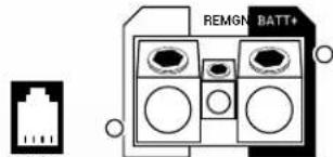
BATT+
This must be connected to the positive terminal (+12V) of the car's battery via a 60A fuse. The fuse must be located within 18 inches of the battery. Use of 8GA or larger OFC (oxygen-free) copper wire is recommended for best performance.
TRI-LIGHT
Tri-light LED amplifier status indicators will change colors according to an array of system variables.
Blue - Standard Operation
Green - Over Voltage Warning/Thermal Protection Red - Internal Fuse Blown
Amber - DC/Short Protection
OTM monitors amplifier Internal temperatures, and if abnormal temperatures are achieved, OTM will make minor adjustments to output power to allow the amplifier to return to normal operating temperatures without interruption.
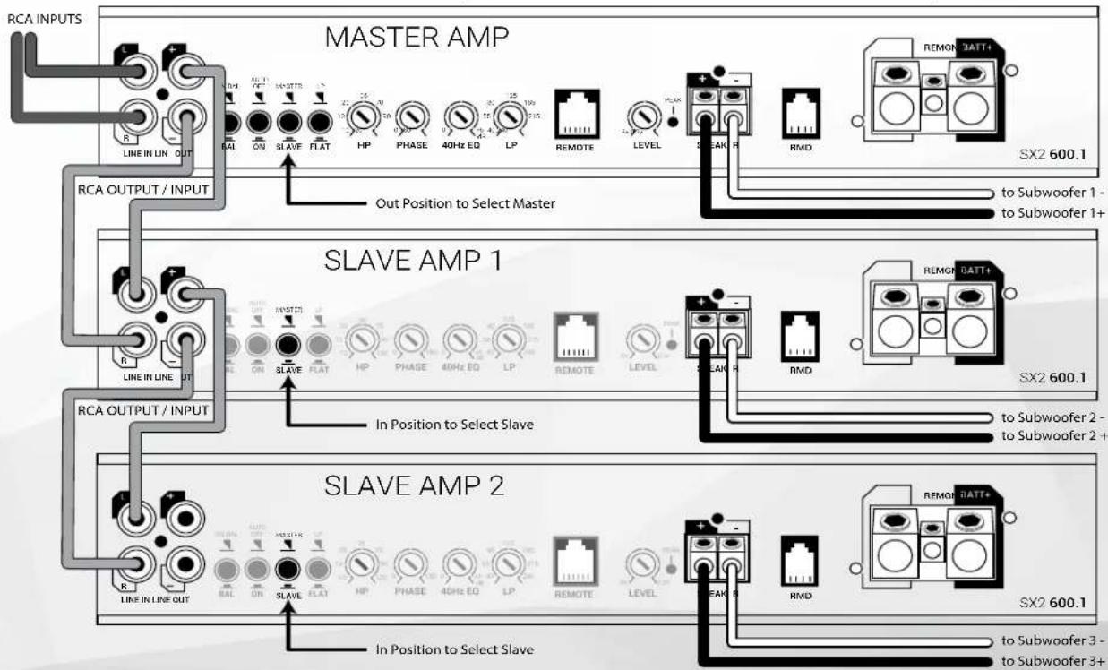
SX2 600.1 Linked Mode (multiple subwoofer/amplifiers)
Repeat process for as many Slave amplifiers needed
Adjustments for gain, crossover, EQ, and phase are only needed on Master amplifier, slave amp controls are disabled in Slave mode
SX2 600.1
MONOBLOCK POWER AMPLIFIER

Master / Slave Strapped
Do you have a monster subwoofer that you want to power? No problem! You can strap two SX2 600.1 together to form a single output for 1200 watts at 2 ohm.
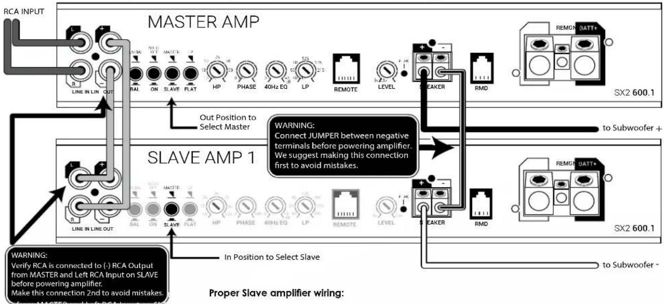
SX2 600.1 Strapped Mode (multiple amplifiers / single subwoofer 2 minimum)
Proper Slave amplifier wiring:
Utilizing this configuration will result in a very powerful amplifier but with that power comes responsibility. Proper wiring is paramount so please read and understand these steps before proceeding.
Slave amplifier effectively becomes negative channel in this system. The Slave amplifier Positive output terminal is now the Negative speaker output in this system configuration. A jumper between the Master negative (marked-) terminal and the Slave negative (marked-) terminal must be connected before powering amplifier. RCA connection between Master and Slave amplifier must be correctly connected before powering amplifier.
Warning: Failure to correctly follow these steps can damage both amplifiers and is not covered under warranty.
Adjustments for gain, crossover, EQ, and phase are only needed on Master amplifier, slave amp controls are disabled in Slave mode
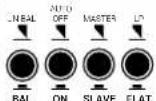
SX2 1200.1
MONOBLOCK POWER AMPLIFIER
LINE IN
Connect preamp signal cables from the source unit to these terminals.
LINE OUT
Used to connect multiple amplifiers without degrading signal strength via internal line driver. Also utilized when connecting amplifiers together in a Master/Slave configuration (See Master/Slave).
BAL/UNBAL
Select Balanced or Unbalanced inputs based on your input source's design for best S/N performance.
AUTO ON
Auto-on is useful when connecting to an OEM system that does not offer a Remote turn-on lead to activate the amplifier. When connecting directly to the amplifier using a high-level input signal the circuit can detect the input voltage (BTL <1V DC) and activate the amplifier. If your system has a standard remote turn-on lead use the standard
REM input. If it is an OEM system that slays active even with the radio off (voltage on signal wires) move the switch to the OFF position and locate an alternative circuit or PAC L.O.C.PRO device to activate the amplifier. See Source Balanced/Unbalanced for High Level input wiring.
MASTER/SLAVE
Select Master if single amplifier or not connecting multiple amplifiers in either Strapped or Linked mode. Strapped mode will allow two SX2 1200.1 amplifiers to be combined together as a single amp and drive a 2 load in excess of 2400 watts. Linked mode will allow any number of SX2 1200.1 amplifiers to be connected to a Master SX2 1200.1. Allowing all connected amplifier adjustments to be made via the Master amplifier. See diagrams for correct wiring configurations.
LP/FLAT
Select LP for subwoofer applications, will also activate REMOTE input. Select FLAT for use with external processor or for full range applications.
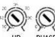
HP
HP adjusts a highpass crossover that can be used as a subsonic filter. Use in conjunction with LP/ FLAT switch, if LP is selected, then adjust HP dial to desired crossover point, variable from 10Hz - 120Hz @ 24dB per octave. Typically used for vented subwoofer systems and is adjusted to the port tuning frequency to prevent overdriving of the subwoofer.
PHASE
Set to 180^ on amplifier to allow adjustment from RBPC. The unique feature of the RBPC with BASS SHIFT allows for perfect adjustment of not only the subwoofer level but also 0 - 180^ of phase adjustment from the listening position. Properly adjusting phase will allow enhanced bass response, dynamics and impact at any volume. If not utilizing the RBPC, adjust phase directly from amplifier. See RBPC instructions for proper adjustment.
SX2 1200.1


LINE IN LINE OUT

SPEAKER


SX21200.1
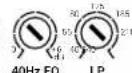
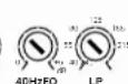
40Hz EQ
Up to 6dB of bass boost @ 40Hz. Adjust this with the mindset of less is more as usually only minor adjustments (if any) are needed for most modern systems. Most systems will benefit from proper Phase adjustment without having to use boost.
LP
Variable lowpass crossover frequency adjustment from 40Hz - 240Hz @ 24dB per octave.
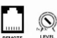
REMOTE
Selecting LP activates this port. This port is for connecting the (RBPC) remote bass level and phase controller with BASS SHIFT. The unique feature of the RBPC with BASS SHIFT® allows for perfect adjustment of not only the subwoofer level but also 0 - 180^ of phase adjustment from the listening position. Properly adjusting phase will allow enhanced bass response, dynamics and impact at any volume. To adjust, play a test tone close to the crossover overlap you have the system adjusted to, typically in the 50 - 100Hz range. With all system speakers playing and at a moderate volume, slowly adjust the phase dial on the RBPC across the entire range. When the subwoofer is in phase with the other speakers in the system, you
should be able to detect a rise in volume, "the sweet spot." Now return the control to the sweet spot and make small adjustments +/- until you maximize the output. You have now completed adjusting the phase and should not have to adjust this again. Use the level control to adjust the subwoofer output to your preference based on music program material. NOTE: To allow adjustment from the RBPC controller, the phase adjustment must be set to the 180^ position on the amplifier.
PEAK
Peak output LED indicator. Helpful when used for subwoofer level adjustment. Adjust LEVEL so PEAK LED flashes when driving amplifier hard, but not so much that the LED stays on continuously. Light will illuminate when rated output voltage is achieved.
FULL RANGE USE
SX2 Monoblocks are full range capable. Unlike traditional monoblocks that are only used in bass applications, the SX2 1200.1 can be configured for use as a powerful mono amplifier or used in pairs to create an incredibly powerful stereo output. Applications such as driving a large number of full range speakers with 1200 watts per channel or a strong component set with unlimited channel separation with independent left and right amplifiers.
SX2 1200.1
MONOBLOCK POWER AMPLIFIER
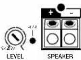
LEVEL
Input sensitivity, used to properly match input signal levels from signal source and maximize amplifier output while eliminating noise. Level is not a volume control, level matching only. Adjust LEVEL to match source output voltage. For reference, a typical aftermarket radio ranges from 2v-4v of output. At minimum, use of a multi-meter and test program material is critical for this step.
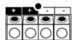
SPEAKER
Speaker connections are labeled + / - and will accept up to 10GA wire. Minimum speaker impedance is 1
RMD
RMD port is for connecting an optional Remote Monitoring Display (RMD). The RMD allows real-time viewing of system voltage.
MASTER/SLAVE
Linked mode is used when utilizing multiple amplifiers and speakers with the desire to have them act in concert. The Master amplifier will control all Slave amplifiers in this configuration. Setting the Master amplifier will allow the Slave amplifiers to become exact duplicates of the Master, therefore making setup easy while having predictable results.
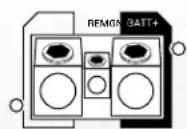
GND
This must be connected to the negative terminal of the car's battery or bolted to a clean, unpainted part of the vehicle's chassis.
REMOTE
This must be connected to switched +12V usually a trigger wire coming from the head unit or ignition. If the system does not have a standard remote turn-on, use of the AUTO ON feature maybe useful.
BATT+
This must be connected to the positive terminal (+12V) of the car's battery via a 80A fuse. The fuse must be located within 18 inches of the battery. Use of 4GA or larger OFC (oxygen-free) copper wire is recommended for best performance.
TRI-LIGHT
Tri-light LED amplifier status indicators will change colors according to an array of system variables.
Blue - Standard Operation
Green - Over Voltage Warning/Thermal Protection
Red - Internal Fuse Blown
Amber - DC/Short Protection
OTM monitors amplifier Internal temperatures, and if abnormal temperatures are achieved, OTM will make minor adjustments to output power to allow the amplifier to return to normal operating temperatures without interruption.
SX2 1200.1 Linked Mode (multiple subwoofer/amplifiers)
Repeat process for as many Slave amplifiers needed
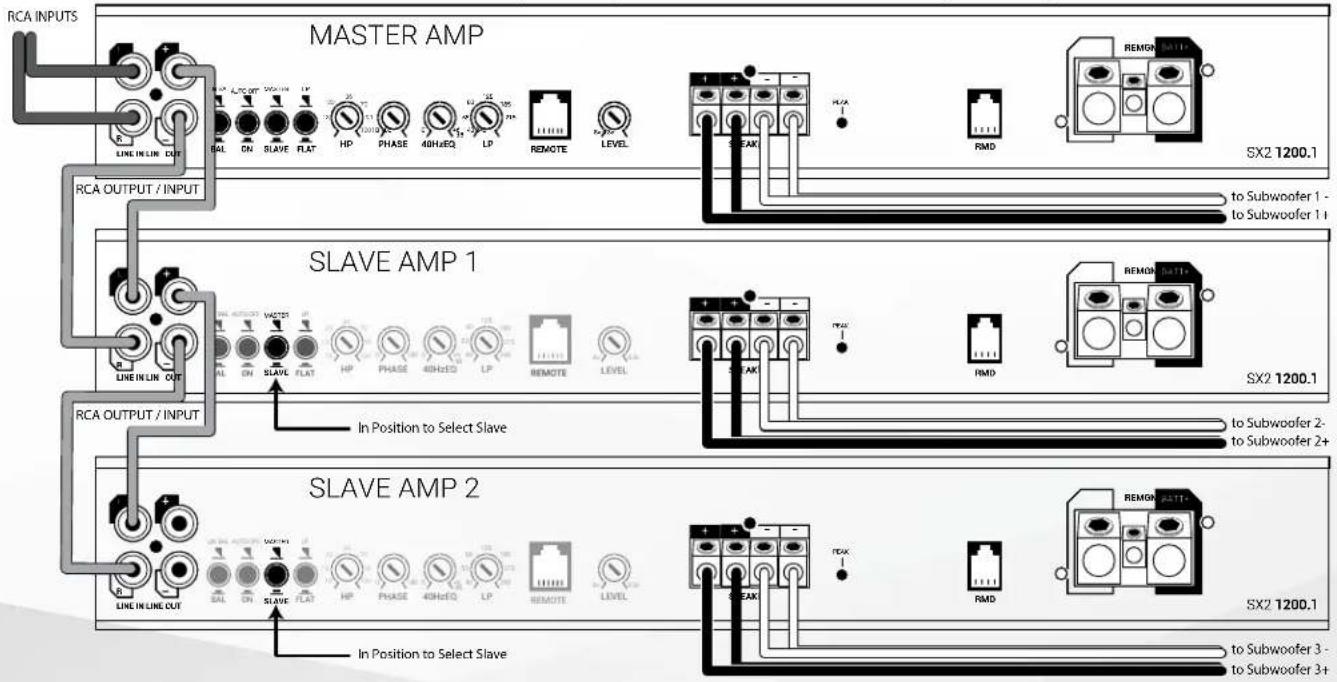
Adjustments for gain, crossover, EQ, and phase are only needed on Master amplifier, slave amp controls are disabled in Slave mode
SX2 1200.1
MONOBLOCK POWER AMPLIFIER
Master / Slave Strapped
Do you have a monster subwoofer that you want to power? No problem! You can strap two SX2 1200.1 together to form a single output for 2400 watts at 2 ohm.
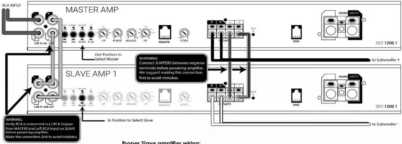
SX2 1200.1 Strapped Mode (multiple amplifiers / single subwoofer 2 minimum)
Proper Slave amplifier wiring:
Utilizing this configuration will result in a very powerful amplifier but with that power comes responsibility. Proper wiring is paramount so please read and understand these steps before proceeding.
Slave amplifier effectively becomes negative channel in this system. The Slave amplifier Positive output terminal is now the Negative speaker output in this system configuration. A jumper between the Master negative (marked-) terminal and the Slave negative (marked-) terminal must be connected before powering amplifier. RCA connection between Master and Slave amplifier must be correctly connected before powering amplifier.
Warning: Failure to correctly follow these steps can damage both amplifiers and is not covered under warranty.
Adjustments for gain, crossover, EQ, and phase are only needed on Master amplifier, slave amp controls are disabled in Slave mode
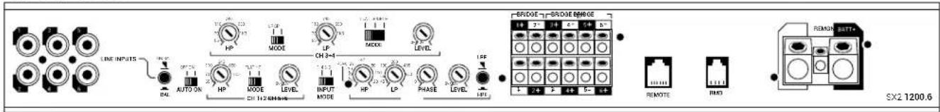
SX2 1200.6
6 CHANNEL POWER AMPLIFIER
LINE IN
Connect preamp signal cables from the source unit to these terminals. Use of 4 OR 6 channels of input signal selectable with INPUT MODE switch.
INPUTS
Select Balanced or Unbalanced inputs based on your input source's design for best S/N performance.
AUTO ON
Auto-on is useful when connecting to an OEM system that does not offer a Remote turn-on lead to activate the amplifier. When connecting directly to the amplifier using a high-level input signal the circuit can detect the input voltage (BTL < 1V DC) and activate the amplifier. If your system has a standard remote turn-on lead use the standard REM input. If it is an OEM system that stays active even with the radio off (voltage on signal wires) move the switch to the OFF position and locate an alternative circuit or PAC L.O.C. PRO device to activate the amplifier. See Source Balanced/Unbalanced for High Level input wiring.
INPUT MODE
Input signal selectable for 4 or 6 channels. If only 4 channels of input signal are available, select 1-4 to allow signal to split to CHS-6. Selecting 5-6 will allow separate signal input but will disable crossovers and RBPC controller. With 5-6 active, only level will remain functional.
HP1+2
Use in conjunction with MODE switch. Selectable disabled (FLAT) or Highpass (HP). If HP is selected, then adjust dial to desired crossover point, variable from 55Hz - 4kHz @ 12dB per octave.
LEVEL
Input sensitivity, used to properly match input signal levels from signal source and maximize amplifier output while eliminating noise. Level is not a volume control, level matching only. Adjust LEVEL to match source output voltage. For reference, a typical aftermarket radio ranges from 2v-4v of output. At minimum, use of a multi-meter and test program material is critical for this step. Independent level controls available for channels 1 + 2 , 3 + 4 and 5 + 6 .
SX2 1200.6
CH 3+4 Controls
Use in conjunction with MODE switches. Selectable disabled (FLAT), Highpass (HP) or Bandpass (BP)/Lowpass (LP).
Select FLAT/HP/LP/BP then adjust to desired crossover point, variable from 55Hz - 4kHz @ 12dB per octave. If LP or BP is desired, move both switches to LP+LP or BP+BP. If Flat or HP is selected, secondary LP/BP switch is disabled.
5+6PEAK
Peak output LED indicator for channels 5 + 6 .Helpful when used for subwoofer level adjustment. Adjust LEVEL so PEAK LED flashes when driving amplifier hard, but not so much that the LED stays on continuously. Light will illuminate when rated output voltage is achieved.
CH 5+6 Controls
Use in conjunction with INPUT MODE switches. Note: Selecting CH5-6 on INPUT MODE will disable 5-6 controls with exception of level. Highpass/subsonic/bypass (HP), Lowpass (LP).
Select then adjust to desired crossover point, variable from 55Hz - 4kHz @ 12dB per octave.
LPF/HPF
Select LPF for subwoofer applications, will also activate REMOTE input. Select HPF for use with external processor or for full range applications. HP disables crossover functions.
HP
HP adjusts a highpass crossover that can be used as a subsonic filter. Use in conjunction with LPF/ HPF switch. If LPF is selected, then adjust HP dial to desired crossover point, variable from 10Hz - 50kHz @ 24dB per octave. Typically used for vented subwoofer systems and is adjusted to the port tuning frequency to prevent overdriving of the subwoofer.
PHASE
Set to 180^ on amplifier to allow adjustment from RBPC. The unique feature of the RBPC with BASS SHIFT allows for perfect adjustment of not only the subwoofer level but also 0 - 180^ of phase adjustment from the listening position. Properly adjusting phase will allow enhanced bass response, dynamics and impact at any volume. If not utilizing the RBPC, adjust phase directly from amplifier. See RBPC instructions for proper adjustment.
SPEAKER
Speaker connections can be configured in Stereo (1 and 2, 3 and 4 or 5 and 6). Mono (1 + 2, 3 + 4 and 5 + 6) and 5 channel (1 and 2, 3 and 4, 5 + 6) . Minimum speaker impedance is 2 in Stereo or 4 Mono. When bridging the amplifier into a Mono load, only the 1+ and 2- , 3+ and 4- or 5+ and 6- outputs on the bridged channels will be used. Accepts up to 10GA wire.
SX2 1200.6
6 CHANNEL POWER AMPLIFIER
REMOTE
Selecting INPUT MODE 1-4 plus LP for channels 5 + 6 activates this port. This port is for connecting the (RBPC) remote bass level and phase controller with BASS SHIFT. The unique feature of the RBPC with BASS SHIFT allows for perfect adjustment of not only the subwoofer level but also 0 - 180^ of phase adjustment from the listening position. Properly adjusting phase will allow enhanced bass response, dynamics and impact at any volume. To adjust, play a test tone close to the crossover overlap you have the system adjusted to, typically in the 50 - 100Hz range. With all system speakers playing and at a moderate volume, slowly adjust the phase dial on the RBPC across the entire range. When the subwoofer is in phase with the other speakers in the system, you should be able to detect a rise in volume, "the sweet spot." Now return the control to the sweet spot and make small adjustments +/- until you maximize the output. You have now completed adjusting the phase and should not have to adjust this again. Use the level control to adjust the subwoofer output to your preference based on music program material.
RMD
RMD port is for connecting an optional Remote Monitoring Display (RMD). The RMD allows real-time viewing of system voltage.
GND
This must be connected to the negative terminal of the car's battery or bolted to a clean, unpainted part of the vehicle's chassis.
REM
This must be connected to switched +12V usually a trigger wire coming from the head unit or ignition. If the system does not have a standard remote turn-on, use of the AUTO ON feature maybe useful.
BATT+
This must be connected to the positive terminal (+12V) of the car's battery via a 70A fuse. The fuse must be located within 18 inches of the battery. Use of 4GA or larger OFC (oxygen-free) copper wire is recommended for best performance.
TRI-LIGHT
Tri-light LED amplifier status indicators will change colors according to an array of system variables.
Blue - Standard Operation
Green-Over Voltage Warning/Thermal Protection
Amber - DC/Short Protection
Red - Internal Fuse Blown
OTM monitors amplifier internal temperatures and if abnormal temperatures are achieved, OTM will make minor adjustments to output power to allow the amplifier to return to normal operating temperatures without interruption.
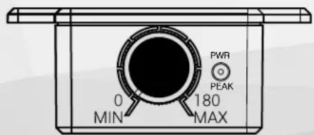
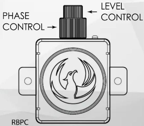
RBPC
REMOTE BASS AND PHASE CONTROL WITH BASS SHIFT®
RBPC
The first step if utilizing the RBPC and planning on using the Phase adjustment feature is to set the Phase on the connected amplifier to 180^ (except SX2 800.4).
FEATURES
The unique feature of the RBPC with BASS SHIFT allows for perfect adjustment of not only the subwoofer level but also 0 - 180^ of phase adjustment from the listening position. Properly adjusting phase will allow enhanced bass response, dynamics and impact at any volume.
If not utilizing the RBPC at all or not the phase adjustment, adjust phase directly from amplifier.
Along with the tuning of bass level and phase, the RBPC also offers amplifier status for power and peak with the onboard LED. If adjusting level, you can easily detect if you are driving the amplifier via the peak indication changing from flashing to solid.
INSTALLATION
Connect the RBPC to the amplifier via the included connection cable. Find a suitable location that allows easy access to the controls and mount the RBPC.
TUNING
To adjust, play a test tone close to the crossover overlap you have the system adjusted to, typically in the 50-100Hz range. With all system speakers playing and at a moderate volume, slowly adjust the phase dial on the RBPC across the entire range. When the subwoofer is in phase with the other speakers in the system, you should be able to detect a rise in volume, "the sweet spot." Now return the control to the sweet spot and make small adjustments +/- until you maximize the output. You have now completed adjusting the phase and should not have to adjust this again. Use the level control to adjust the subwoofer output to your preference based on music program material.
SYSTEM TUNING - BASIC
BASS SHIFT
- Install all system fuses.
- Set the amplifier's input sensitivity (LEVEL) controls to their minimum positions (full counterclockwise).
- Set all amplifier crossovers according to your system's design.
- Make preliminary adjustments to the crossover frequency, usually 80Hz is a good starting point for high and low pass. It may be necessary to fine tune the crossover frequency later for the best overall sound quality.
- If using a RBPC, set it to maximum (full clockwise).
- Turn the headunit on with the volume set to minimum.
- Visually check the amplifier has turned on by the power LED.
- Check the condition of all other components to make sure they are powered up.
- Set the headunit's tone controls, balance, and fader to the center (flat) position. Turn off any loudness or other signal processing features.
- Set the volume control of the headunit to maximum volume. Play music you typically listen to through the system.
- Turn up the sensitivity or input level control on the amplifier until the speakers reach maximum undistorted output.
- Repeat sensitivity level adjustments for all other amplifiers.
-
Reduce the headunit's volume to a comfortable level.
-
Listen to various musical selections to check overall system balance. Compare front to rear, midbass to midrange, etc. If one speaker set is too loud compared to another, then its level must be lowered to blend correctly with the other speakers.
Note: For subwooers controlled by the Remote level control, keep the level setting from step 11 or 12. Use the control to blend subwooers with the rest of the system. The correct subwoofer volume will change depending on road noise and differences in recordings. - Fine tune crossover frequencies to achieve the smoothest possible blending of each speaker set.
- Adjust the Bass Equalization Controls on the amplifier, headunit or processor upstream if necessary to increase output.
Note: Use these controls sparingly. Every 3dB of boost requires double the power at 45Hz . If your subwoofer system requires a lot of boost to sound good, there may be a problem. Look for out-of-phase woofers, a leaking subwoofer box, or incorrect box size.
- With all levels set correctly, the system will reach overall maximum undistorted output at the volume level set in step 10.
Advanced Tuning (Recommended Method)
- Disconnect all speaker wires from amplifier.
- Disconnect RCA's from any other system amplifiers.
- If using RBPC, turn LEVEL fully clockwise. (Full output)
- Select a test tone within the range of the output you are going to connect the amplifier. Highpass (5kHz), Midrange (1kHz), Bass 80Hz.
- Adjust source unit to 85% full output and play selected test tone.
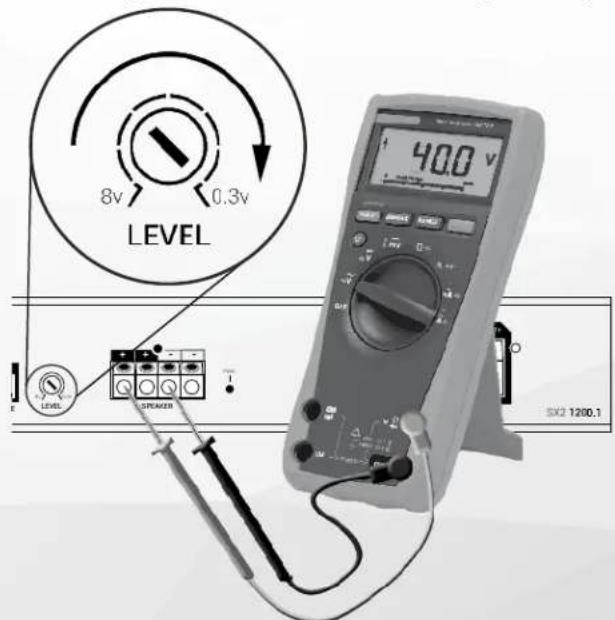
- With the DMM set to AC voltage, measure output of amplifier (only one channel per level control is needed).
- With test tone playing, slowly turn level control clockwise until target voltage is displayed on DMM. (see diagram below)
- Repeat for all amplifiers/pairs of channels in system.
- You have now set your amplifier(s) to perform at maximum output. Do not adjust the level higher from this point forward. Reconnect speakers.
Amplifier Target Output Voltage
| SX2 400.2 | 21 |
| SX2 800.4 | 25 |
| SX2 1200.6 | 25 |
| SX2 600.1 | 34 |
| SX2 1200.1 | 40 |
- Adjust all crossovers and listen to the system.
Level Matching:
If output levels do not match, determine which speakers are too loud in comparison to the others. Select the level control to these "lauder" speakers and lower it to match the others. Listen again and readjust if needed. Do not increase levels higher than the set point that was determined in step 7. This method will provide the best dynamic range, exhibit no distortion and have an ultra-low noisefloor.
Turn LEVEL slowly clockwise until DMM reads target voltage
TRI-LIGHT
Troubleshooting is made easy thanks to the Tri-Light status indicators. If amplifier is not working, reference these first to access current status and address as needed.
Tri-light LED amplifier status indicators will change colors according to an array of system variables.
No Illumination - No Power
Blue - Standard Operation
Green - Over Voltage Warning/Thermal Protection
Red - Internal Fuse Blown
Amber - DC/Short Protection
NO POWER:
Check voltage at the amplifier with a DMM (volt meter), +12v and R (with head unit on) the voltage should register between 11.5V and 16.1V when using the attached ground lead of the amplifier. Check that the amplifier's ground is good and has a solid connection. Check fuse at the battery. Use a meter to verify connection from one end of the fuse to the other, breaks may not always be visible. If the fuse is blown, check the power wire and also the amplifier for a short. If the short is in the amplifier itself, see your
Phoenix Gold dealer. If no short is present, replace the fuse.
GREEN LED ILLUMINATED:
Check charging system for cause of high voltage. Measure with DMM and verify voltage is not exceeding 16.1V with vehicle running and RPM above 2000. For thermal protection, check for adequate ventilation or if restricted ventilation, may require addition of fans.
BLUE LED ILLUMINATED, NO SOUND:
Turn the amplifier off and check all input and output signal cables and power connections. Check the speakers for shorts with a DMM (volt meter) or by connecting them to another audio source. After making sure everything is correct, turn the amplifier on again.
RED LED ILLUMINATED:
Internal Fuse Blown, visit an authorized dealer for service and troubleshooting. The advanced design of the SX2 amplifiers should protect the amplifier in almost every circumstance, a blown internal fuse is a red flag meaning that something out of the ordinary is happening and should be investigated before replacing fuse. Example would be external fuse used is higher than recommended value.
AMBER LED ILLUMINATED:
DC/Short Protection. Check all connections. Disconnect all speaker wires and restart amplifier. If status returns to Blue, then meter speaker leads and verify not shorted to one another or to ground. Reconnect speaker leads and retest.
BLUE LED ILLUMINATED, NO SOUND FROM ONE OR MORE CHANNELS:
Check the balance control in the head unit. Check speaker connections. Check signal input connection. Very low output: Check your head unit's fader control or the amplifier's input sensitivity level. Make sure subsonic frequency control is not set too high and LP frequency control is not set too low at the same time.
FREQUENT AMPLIFIER SHUTDOWN WITH AUTOMATIC RECOVERY:
This indicates chronic amplifier thermal shutdown because of operation at consistently high internal temperatures. High operating temperature can be caused by inadequate ventilation. Make sure you are not running a lower than recommend impedance. Also check for damaged speakers or passive crossover systems. Finally, chronic thermal shutdown may result from otherwise normal operation of the amplifier at elevated output power levels, which can be resolved by providing additional amplifier cooling, installing a higher-power amplifier, or reducing amplifier output level.
POWER CYCLES ON/OFF QUICKLY:
If the power indicator is going off repeatedly when the audio system is on, check all ground connections. Check the amplifier's connection to the battery. Check battery voltage. If low, recharge or replace the battery.
SOURCE - BALANCED OR UNBALANCED
How to determine If your source (last component sending signal to amplifier) is a balanced or unbalanced signal:
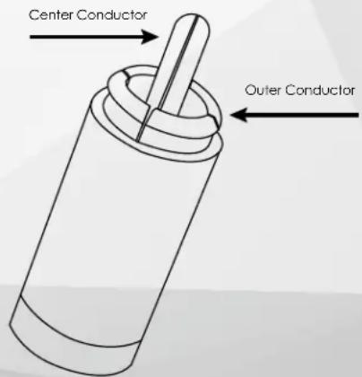
For car audio, we use standard RCA connectors with 2 main connection points, the center pin and the outer connector. RCA connectors can be used in both Balanced and Unbalanced systems.
Unbalanced benefit from the use of Coaxial constructed cables, and in contrast Balanced systems benefit from Twisted Pair construction. These are not to be confused with XLR Pro Audio Balanced connectors that have 3 conductors and are a different type of balanced connection.
This is a simplified explanation, but suitable enough to determine the type of system you are working with. In an Unbalanced system, the outer part of the RCA will reference to ground.
To test, use your DMM set to continuity and hold one lead to chassis ground and the other to the outer RCA connection on your source. If you read continuity, then your system is Unbalanced and you can adjust your settings and RCA construction type to suit this style. If there is no continuity then the system is Balanced and again you can adjust for this system.
High Level Inputs:
If utilizing high level inputs select Balanced as the input type. Then use a standard RCA cable with one side cut off to connect source output wires. Then connect the RCA side to the input of the amplifier. The input is capable of accepting up to 16V of input signal.
ESPECIFICACIONES
55Hz-4kHz @ 12dB/Oct
LP 45Hz - 1K @ 12dB/Oct
55Hz-4kHz @ 12dB/Oct
LP 45Hz -1K @12dB/Oct
Designed and Engineered in the USA
Made in China
Phoenix Gold Product Warranty
LIMITED WARRANTY ON AMPLIFIERS
Phoenix Gold warrants this product to be free of defects in materials and workmanship for a period of one (1) years from the original date of purchase. This warranty is not transferable and applies only to the original purchaser from an authorized Phoenix Gold dealer in the United States of America only. Should service be necessary under this warranty for any reason due to manufacturing defect or malfunction, Phoenix Gold will (at its discretion) repair or replace the defective product with new or remanufactured product at no charge. Damage caused by the following is not covered under warranty: accident, misuse, abuse, product modification or neglect, failure to follow installation instructions, unauthorized repair attempts, misrepresentations by the seller. This warranty does not cover incidental or consequential damages and does not cover the cost of removing or reinstalling the unit(s). Cosmetic damage due to accident or normal wear and tear is not covered under warranty.
INTERNATIONAL WARRANTY:
Products purchased outside the United States of America are covered only by that country's Authorized Phoenix Gold reseller and not by Phoenix Gold. Consumers needing service or warranty information for these products must contact that country's reseller for information.