BHP454 - Screwdriver MAKITA - Free user manual and instructions
Find the device manual for free BHP454 MAKITA in PDF.

Frequently Asked Questions - BHP454 MAKITA
User questions about BHP454 MAKITA
0 question about this device. Answer the ones you know or ask your own.
Ask a new question about this device
Download the instructions for your Screwdriver in PDF format for free! Find your manual BHP454 - MAKITA and take your electronic device back in hand. On this page are published all the documents necessary for the use of your device. BHP454 by MAKITA.
USER MANUAL BHP454 MAKITA
GB Cordless Hammer Driver Drill Instruction manual
natural_image
Line drawing of a Makital electric drill press with visible components and no text or symbols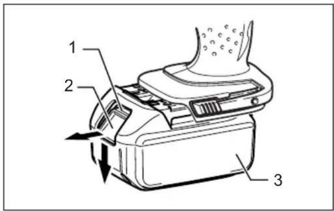
text_image
Technical diagram of a device with numbered parts and directional arrows indicating motion or assembly.1
text_image
42
text_image
53
text_image
A 6 B4
text_image
1 2 75
text_image
8 1 2 3 4 5 6 7 86
text_image
9 10 117
text_image
12 13 16 15 148
text_image
179
text_image
18 1910
text_image
20 2111 12
text_image
16 22 23[Non-Text]
natural_image
Line drawing of a hand using a drill bit to press or install a screwdriver (no text or symbols present)13 14
text_image
24[Non-Text]
text_image
2515 16
text_image
26 27[Non-Text]
text_image
28 29 3017 18
text_image
31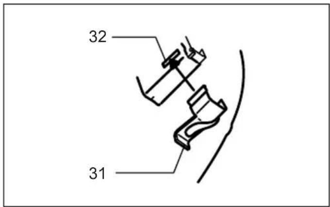
text_image
32 3119
ENGLISH (Original instructions)
Explanation of general view
| 1. Red part | 12. Steel band | 23. Screw |
| 2. Button | 13. Grip base | 24. Blow-out bulb |
| 3. Battery cartridge | 14. Side grip | 25. Limit mark |
| 4. Switch trigger | 15. Protrusion | 26. Rear cover |
| 5. Lamp | 16. Groove | 27. Screws |
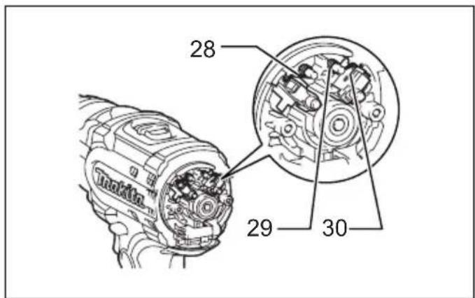
| 6. Reversing switch lever | 17. Sleeve | 28. Arm |
| 7. Speed change lever | 18. Bit holder | 29. Spring |
| 8. Action mode change lever | 19. Bit | 30. Recesed part |
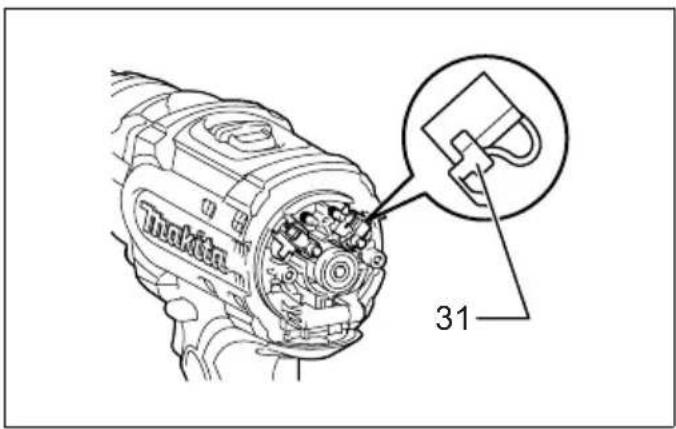
| 9. Adjusting ring | 20. Depth rod | 31. Carbon brush cap |
| 10. Graduation | 21. Clamp screw | 32. Hole |
| 11. Arrow | 22. Hook |
SPECIFICATIONS
| Model BHP444 BHP454 | |||
| Capacities | Concrete 14 mm 16 mm | ||
| Steel 13 mm 13 mm | |||
| Wood 50 mm 65 mm | |||
| Wood screw 6 mm x 75 mm 10 mm x 89 mm | |||
| Machine screw 6 mm | |||
| No load speed (min ^-1 ) | High (2) 0 - 1,700 | ||
| Low (1) | 0 - 400 | ||
| Blows per minute (min ^-1 ) | High (2) | 0 - 25,500 | |
| Low (1) | 0 - 6,000 | ||
| Overall length | 243 mm | ||
| Net weight | 2.3 kg | 2.4 kg | |
| Rated voltage | D.C. 14.4 V | D.C. 18 V | |
- Due to our continuing program of research and development, the specifications herein are subject to change without notice.
- Specifications may differ from country to country.
• Weight, with battery cartridge, according to EPTA-Procedure 01/2003
Intended use
ENE039-1
The tool is intended for impact drilling in brick, concrete and stone as well as for drilling without impact in wood, metal, ceramic and plastic.
General Power Tool Safety Warnings
GEA010-1

WARNING Read all safety warnings and all
instructions. Failure to follow the warnings and instructions may result in electric shock, fire and/or serious injury.
Save all warnings and instructions for future reference.
SPECIFIC SAFETY RULES
GEB003-4
DO NOT let comfort or familiarity with product (gained from repeated use) replace strict adherence to hammer drill safety rules. If you use this power tool unsafely or incorrectly, you can suffer serious personal injury.
- Wear ear protectors when impact drilling. Exposure to noise can cause hearing loss.
- Use auxiliary handle(s), if supplied with the tool. Loss of control can cause personal injury.
- Hold power tool by insulated gripping surfaces, when performing an operation where the cutting accessory may contact hidden wiring or its own cord. Cutting accessory contacting a "live" wire may make exposed metal parts of the power tool "live" and could give the operator an electric shock.
- Always be sure you have a firm footing. Be sure no one is below when using the tool in high locations.
- Hold the tool firmly with both hands.
- Keep hands away from rotating parts.
- Do not leave the tool running. Operate the tool only when hand-held.
- Do not touch the bit or the workpiece immediately after operation; they may be extremely hot and could burn your skin.
- Some material contains chemicals which may be toxic. Take caution to prevent dust inhalation and skin contact. Follow material supplier safety data.
SAVE THESE INSTRUCTIONS.
WARNING:
MISUSE or failure to follow the safety rules stated in this instruction manual may cause serious personal injury.
IMPORTANT SAFETY INSTRUCTIONS
ENC007-4
FOR BATTERY CARTRIDGE
- Before using battery cartridge, read all instructions and cautionary markings on (1) battery charger, (2) battery, and (3) product using battery.
- Do not disassemble battery cartridge.
- If operating time has become excessively shorter, stop operating immediately. It may result in a risk of overheating, possible burns and even an explosion.
- If electrolyte gets into your eyes, rinse them out with clear water and seek medical attention right away. It may result in loss of your eyesight.
- Do not short the battery cartridge:
(1) Do not touch the terminals with any conductive material.
(2) Avoid storing battery cartridge in a container with other metal objects such as nails, coins, etc.
(3) Do not expose battery cartridge to water or rain. A battery short can cause a large current flow, overheating, possible burns and even a breakdown. - Do not store the tool and battery cartridge in locations where the temperature may reach or exceed 50^ C ( 122^ F).
- Do not incinerate the battery cartridge even if it is severely damaged or is completely worn out. The battery cartridge can explode in a fire.
- Be careful not to drop or strike battery.
- Do not use dropped or struck battery.
SAVE THESE INSTRUCTIONS.
Tips for maintaining maximum battery life
- Charge the battery cartridge before completely discharged. Always stop tool operation and charge the battery cartridge when you notice less tool power.
- Never recharge a fully charged battery cartridge. Overcharging shortens the battery service life.
- Charge the battery cartridge with room temperature at 10^ C - 40^ C ( 50^ F - 104^ F). Let a hot battery cartridge cool down before charging it.
FUNCTIONAL DESCRIPTION
CAUTION:
- Always be sure that the tool is switched off and the battery cartridge is removed before adjusting or checking function on the tool.
Installing or removing battery cartridge (Fig. 1)
- Always switch off the tool before insertion or removal of the battery cartridge.
- To remove the battery cartridge, withdraw it from the tool while sliding the button on the front of the cartridge.
- To insert the battery cartridge, align the tongue on the battery cartridge with the groove in the housing and slip it into place. Always insert it all the way until it locks in place with a little click. If you can see the red part on the upper side of the button, it is not locked completely. Insert it fully until the red part cannot be seen. If not, it may accidentally fall out of the tool, causing injury to you or someone around you.
- Do not use force when inserting the battery cartridge. If the cartridge does not slide in easily, it is not being inserted correctly.
Switch action (Flg. 2)
CAUTION:
- Before inserting the battery cartridge into the tool, always check to see that the switch trigger actuates properly and returns to the "OFF" position when released.
To start the tool, simply pull the switch trigger. Tool speed is increased by increasing pressure on the switch trigger. Release the switch trigger to stop.
Lighting up the front lamp (Flg. 3)
CAUTION:
- Do not look in the light or see the source of the light directly.
Pull the switch trigger to light up the lamp. The lamp keeps on lighting while the switch trigger is being pulled. The lamp goes out 10 -15 seconds after releasing the trigger.
NOTE:
- Use a dry cloth to wipe the dirt off the lens of lamp. Be careful not to scratch the lens of lamp, or it may lower the illumination.
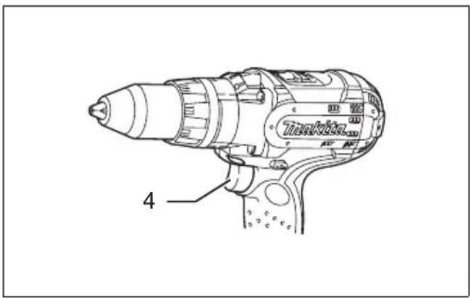
Reversing switch action (Fig. 4)
This tool has a reversing switch to change the direction of rotation. Depress the reversing switch lever from the "A" side for clockwise rotation or from the "B" side for counterclockwise rotation.
When the reversing switch lever is in the neutral position, the switch trigger cannot be pulled.
CAUTION:
- Always check the direction of rotation before operation.
- Use the reversing switch only after the tool comes to a complete stop. Changing the direction of rotation before the tool stops may damage the tool.
- When not operating the tool, always set the reversing switch lever to the neutral position.
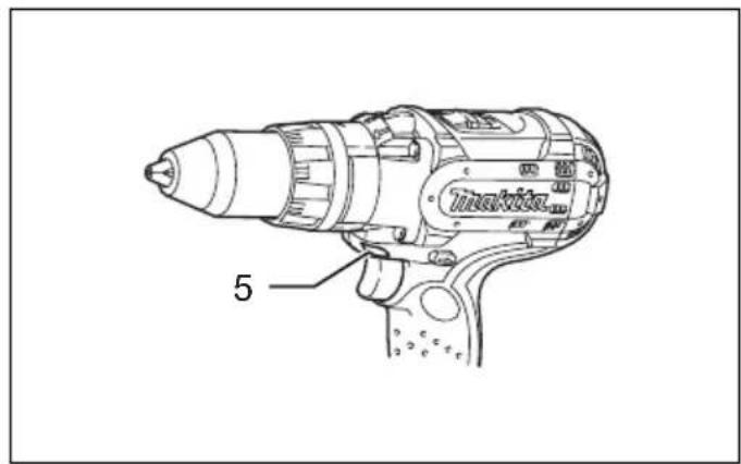
Speed change (Fig. 5)
To change the speed, first switch off the tool and then slide the speed change lever to the "2" side for high speed or, "1" side for low speed. Be sure that the speed change lever is set to the correct position before operation. Use the right speed for your job.
CAUTION:
- Always set the speed change lever fully to the correct position. If you operate the tool with the speed change lever positioned halfway between the "1" side and, "2" side, the tool may be damaged.
- Do not use the speed change lever while the tool is running. The tool may be damaged.
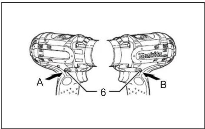
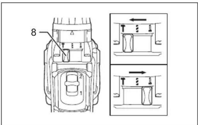
Selecting the action mode (Fig. 6)
This tool employs an action mode change lever. Select one of the three modes suitable for your work needs by using this lever.
For rotation only, slide the lever so that it points toward the mark on the tool body. For rotation with hammering, slide the lever so that it points toward the mark on the tool body. For rotation with clutch, slide the lever so that the it points toward the mark on the tool body.
NOTE:
- When changing the position from “ ” to “ ”, it may be a little difficult to slide the mode change lever. At this time, switch on and run the tool for a second at the “ ” position, then stop the tool and slide to your desired position.
CAUTION:
- Always set the lever correctly to your desired mode mark. If you operate the tool with the lever positioned halfway between the mode marks, the tool may be damaged.
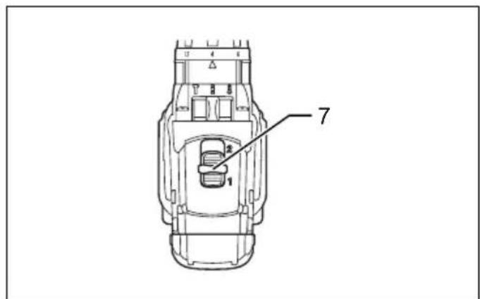
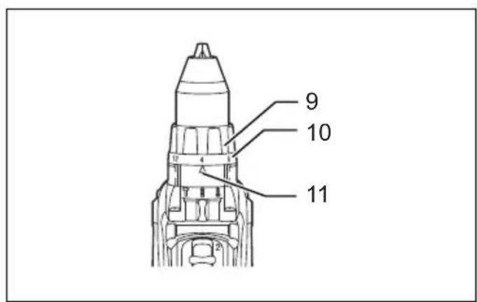
Adjusting the fastening torque (Flg. 7)
The fastening torque can be adjusted in 16 steps by turning the adjusting ring so that its graduations are aligned with the arrow on the tool body. The fastening torque is minimum when the number 1 is aligned with the arrow, and maximum when the number 16 is aligned with the arrow.
Before actual operation, drive a trial screw into your material or a piece of duplicate material to determine which torque level is required for a particular application.
ASSEMBLY
CAUTION:
- Always be sure that the tool is switched off and the battery cartridge is removed before carrying out any work on the tool.
Installing side grip (auxiliary handle) (Fig. 8)
Always use the side grip to ensure operating safety. Insert the side grip so that the protrusions on the grip base and steel band fit in between the grooves on the tool barrel. Then tighten the grip by turning clockwise.
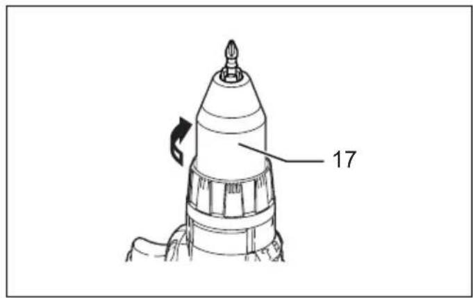
Installing or removing driver bit or drill bit (Flg. 9)
Turn the sleeve counterclockwise to open the chuck jaws. Place the bit in the chuck as far as it will go. Turn the sleeve clockwise to tighten the chuck.
To remove the bit, turn the sleeve counterclockwise.
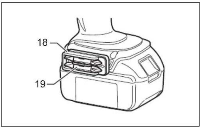
Installing bit holder (Fig. 10)
Fit the bit holder into the protrusion at the tool foot on either right or left side and secure it with a screw. When not using the driver bit, keep it in the bit holders. Bits 45 mm long can be kept there.
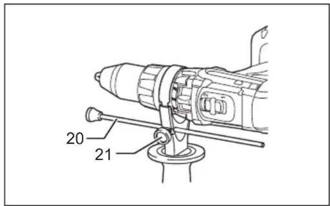
Adjustable depth rod (Flg. 11)
The adjustable depth rod is used to drill holes of uniform depth. Loosen the clamp screw, set to desired position, then tighten the clamp screw.
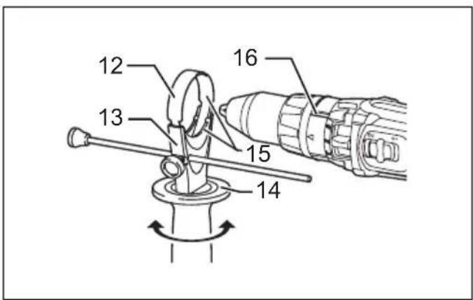
Hook (Fig. 12)
The hook is convenient for temporarily hanging the tool. This can be installed on either side of the tool.
To install the hook, insert it into a groove in the tool housing on either side and then secure it with a screw. To remove, loosen the screw and then take it out.
OPERATION
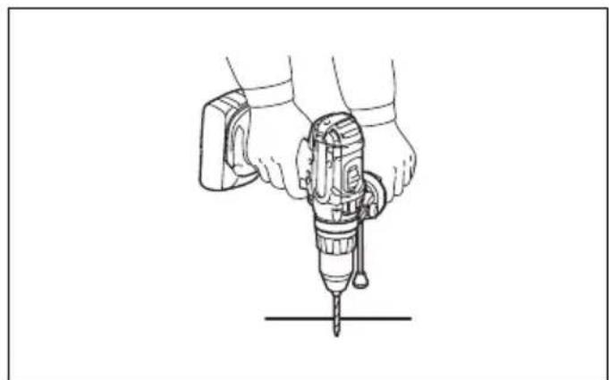
Hammer drilling operation (Flg. 13)
CAUTION:
- There is a tremendous and sudden twisting force exerted on the tool/bit at the time of hole breakthrough, when the hole becomes clogged with chips and particles, or when striking reinforcing rods embedded in the concrete. Always use the side grip (auxiliary handle) and firmly hold the tool by both side grip and switch handle during operations. Failure to do so may result in the loss of control of the tool and potentially severe injury.
First, slide the action mode change lever so that it points to the marking. The adjusting ring can be aligned in any torque levels for this operation. Be sure to use a tungsten-carbide tipped bit. Position the bit at the desired location for the hole, then pull the switch trigger. Do not force the tool. Light pressure gives best results. Keep the tool in position and prevent it from slipping away from the hole. Do not apply more pressure when the hole becomes clogged with chips or particles. Instead, run the tool at an idle, then remove the bit partially from the hole. By repeating this several times, the hole will be cleaned out and normal drilling may be resumed.
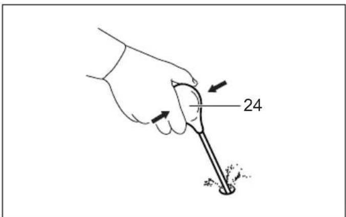
Blow-out bulb (optional accessory) (Fig. 14)
After drilling the hole, use the blow-out bulb to clean the dust out of the hole.
Screwdriving operation
First, slide the action mode change lever so that it points to the marking. Adjust the adjusting ring to the proper torque level for your work. Then proceed as follows.
Place the point of the driver bit in the screw head and apply pressure to the tool. Start the tool slowly and then increase the speed gradually. Release the switch trigger as soon as the clutch cuts in.
NOTE:
- Make sure that the driver bit is inserted straight in the screw head, or the screw and/or bit may be damaged.
- When driving wood screws, predrill pilot holes to make driving easier and to prevent splitting of the workpiece. See the chart.
| Nominal diameter of wood screw (mm) | Recommended size of pilot hole (mm) |
| 3.1 2.0 - 2.2 | |
| 3.5 2.2 - 2.5 | |
| 3.8 2.5 - 2.8 | |
| 4.5 2.9 - 3.2 | |
| 4.8 3.1 - 3.4 | |
| 5.1 3.3 - 3.6 | |
| 5.5 3.6 - 3.9 | |
| 5.8 4.0 - 4.2 | |
| 6.1 4.2 - 4.4 |
NOTE:
- If the tool is operated continuously until the battery cartridge has discharged, allow the tool to rest for 15 minutes before proceeding with a fresh battery.
Drilling operation
CAUTION:
- Pressing excessively on the tool will not speed up the drilling. In fact, this excessive pressure will only serve to damage the tip of your bit, decrease the tool performance and shorten the service life of the tool.
- There is a tremendous force exerted on the tool/bit at the time of hole break through. Hold the tool firmly and exert care when the bit begins to break through the workpiece.
- A stuck bit can be removed simply by setting the reversing switch to reverse rotation in order to back out. However, the tool may back out abruptly if you do not hold it firmly.
- Always secure small workpieces in a vise or similar hold-down device.
- If the tool is operated continuously until the battery cartridge has discharged, allow the tool to rest for 15 minutes before proceeding with a fresh battery.
First, slide the action mode change lever so that it points to the marking. The adjusting ring can be aligned in any torque levels for this operation. Then proceed as follows.
Drilling in wood
When drilling in wood, the best results are obtained with wood drills equipped with a guide screw. The guide screw makes drilling easier by pulling the bit into the workpiece.
Drilling in metal
To prevent the bit from slipping when starting a hole, make an indentation with a center-punch and hammer at the point to be drilled. Place the point of the bit in the indentation and start drilling. Use a cutting lubricant when drilling metals. The exceptions are iron and brass which should be drilled dry.
MAINTENANCE
CAUTION:
- Always be sure that the tool is switched off and the battery cartridge is removed before attempting to perform inspection or maintenance.
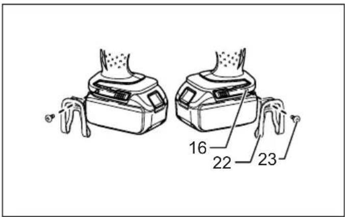
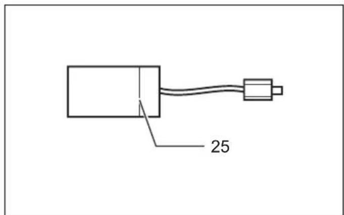
Replacing carbon brushes (Flg. 15)
Replace when they wear down to the limit mark. Keep the carbon brushes clean and free to slip in the holders. Both carbon brushes should be replaced at the same time. Use only identical carbon brushes.
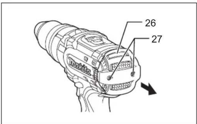
Use a screwdriver to remove two screws then remove the rear cover. (Fig. 16)
Raise the arm part of the spring and then place it in the recessed part of the housing with a slotted bit screwdriver of slender shaft or the like. (Fig. 17)
Use pliers to remove the carbon brush caps of the carbon brushes. Take out the worn carbon brushes, insert the new ones and replace the carbon brush caps in reverse. (Fig. 18)
Make sure that the carbon brush caps have fit into the holes in brush holders securely. (Fig. 19)
Reinstall the rear cover and tighten two screws securely. To maintain product SAFETY and RELIABILITY, repairs, any other maintenance or adjustment should be performed by Makita Authorized Service Centers, always using Makita replacement parts.
ACCESSORIES
CAUTION:
• These accessories or attachments are recommended for use with your Makita tool specified in this manual. The use of any other accessories or attachments might present a risk of injury to persons. Only use accessory or attachment for its stated purpose.
If you need any assistance for more details regarding these accessories, ask your local Makita Service Center.
- Drill bits
- Hammer drill bits
- Screw bits
- Blow-out bulb
- Safety goggles
- Various type of Makita genuine batteries and chargers
- Grip assembly
- Depth rod
- Hook
- Rubber pad assembly
- Wool bonnet
- Foam polishing pad
For Model BHP444
ENG102-2
For European countries only Noise
The typical A-weighted noise level determined according to EN60745:
Sound pressure level ( L_pA ): 85 dB (A)
Sound power level ( L_WA ): 96 dB (A)
Uncertainty (K): 3 dB (A)
Wear ear protection.
Vibration
ENG203-1
The vibration total value (tri-axial vector sum) determined according to EN60745-2-1:
Work mode: impact drilling into concrete
Vibration emission (a _h,ID ): 9 m/s ^2
Uncertainty (K): 2 m/s ^4
ENG302-2
Work mode: drilling into metal
Vibration emission ( a_h,D ): 2.5 m/s ^2 or less
Uncertainty (K): 1.5 m/s²
For Model BHP454
For European countries only
Noise
ENG102-2
The typical A-weighted noise level determined according to EN60745:
Sound pressure level ( L_pA ): 86 dB (A)
Sound power level ( L_WA ): 97 dB (A)
Uncertainty (K): 3 dB (A)
Wear ear protection.
Vibration
ENG203-1
The vibration total value (tri-axial vector sum) determined according to EN60745-2-1:
Work mode: impact drilling into concrete
Vibration emission ( a_h,ID ): 7.5 m/s ^2
Uncertainty (K): 1.5 m/s²
ENG302-2
Work mode: drilling into metal
Vibration emission ( a_h,D ): 2.5 m/s ^2 or less
Uncertainty (K): 1.5 m/s ^4
ENG901-1
- The declared vibration emission value has been measured in accordance with the standard test method and may be used for comparing one tool with another.
- The declared vibration emission value may also be used in a preliminary assessment of exposure.

WARNING:
- The vibration emission during actual use of the power tool can differ from the declared emission value depending on the ways in which the tool is used.
- Be sure to identify safety measures to protect the operator that are based on an estimation of exposure in the actual conditions of use (taking account of all parts of the operating cycle such as the times when the tool is switched off and when it is running idle in addition to the trigger time).
EC Declaration of Conformity
ENH101-12
We Makita Corporation as the responsible manufacturer declare that the following Makita machine(s):
Designation of Machine: Cordless Hammer Driver Drill
Model No./ Type: BHP444, BHP454
are of series production and
Conforms to the following European Directives:
98/37/EC until 28th December 2009 and then with 2006/42/EC from 29th December 2009
And are manufactured in accordance with the following standards or standardised documents:
EN60745
The technical documentation is kept by our authorised representative in Europe who is:
Makita International Europe Ltd., Michigan, Drive, Tongwell, Milton Keynes, MK15 8JD, England
30th January 2009

Tomoyasu Kato Director
Makita Corporation
3-11-8, Sumiyoshi-cho,
Anjo, Aichi, JAPAN
Michigan, Drive, Tongwell,
Milton Keynes, MK15 8JD, Angleterre
30 janvier 2009

Tomoyasu Kato
Directeur
Makita Corporation
3-11-8, Sumiyoshi-cho,
Anjo, Aichi, JAPAN
Makita International Europe Ltd., Michigan, Drive, Tongwell, Milton Keynes, MK15 8JD, England
- Januar 2009

Tomoyasu Kato Direktor
Makita Corporation
3-11-8, Sumiyoshi-cho,
Anjo, Aichi, JAPAN
Michigan, Drive, Tongwell,
Milton Keynes, MK15 8JD, Inghilterra
30 gennaio 2009

Tomoyasu Kato
Direttore
Makita Corporation
3-11-8, Sumiyoshi-cho,
Anjo, Aichi, JAPAN
⚠ WAARSCHUWING Lees alle
Michigan Drive, Tongwell,
Milton Keynes, MK15 8JD, Engeland
30 januari 2009

3-11-8, Sumiyoshi-cho,
Anjo, Aichi, JAPAN
Makita International Europe Ltd., Michigan, Drive, Tongwell,
Milton Keynes, MK15 8JD, Inglaterra
30 de Janeiro de 2009

Tomoyasu Kato
Director
Makita Corporation
3-11-8, Sumiyoshi-cho,
Anjo, Aichi, JAPAN
Michigan, Drive, Tongwell,
Milton Keynes, MK15 8JD, England
- januar 2009

Tomoyasu Kato
Direktør
Makita Corporation
3-11-8, Sumiyoshi-cho,
Anjo, Aichi, JAPAN
Makita International Europe Ltd., Michigan, Drive, Tongwell, Milton Keynes, MK15 8JD, England
30η lavouapíou 2009

Tomoyasu Kato
Διευθυντής
Makita Corporation
3-11-8, Sumiyoshi-cho,
Anjo, Aichi, JAPAN
Makita Corporation
Anjo, Aichi, Japan
884812B994 www.makita.com