
WVQ126 - Ceiling mount bracket PANASONIC - Free user manual and instructions
Find the device manual for free WVQ126 PANASONIC in PDF.

Frequently Asked Questions - WVQ126 PANASONIC
User questions about WVQ126 PANASONIC
0 question about this device. Answer the ones you know or ask your own.
Ask a new question about this device
Download the instructions for your Ceiling mount bracket in PDF format for free! Find your manual WVQ126 - PANASONIC and take your electronic device back in hand. On this page are published all the documents necessary for the use of your device. WVQ126 by PANASONIC.
USER MANUAL WVQ126 PANASONIC
Operating Instructions
Ceiling Mount Bracket
Model No. WV-Q126
Before attempting to connect or operate this product, please read these instructions carefully and save this manual for future use.
The model number is abbreviated in some descriptions in this manual.
ENGLISH VERSION
CONTENTS
Preface 2
Precautions 2
Major Operating Controls 4
Installations 5
Specifications 12
Standard Accessories 12
Preface
This ceiling mount bracket is exclusively designed to mount the camera on a ceiling. Refer to the catalog or the installation guide of the camera for supported cameras.
This bracket can be used for an area with weak pull-out strength such as plasterboard in a double ceiling.
This bracket is an embedded type to reduce the exposed portion of the camera body.
Precautions
Refer installation work to the dealer.
Installation work requires technique and experiences. Failure to observe this may cause fire, electric shock, injury, or damage to the product. Be sure to consult the dealer.
Avoid installing this bracket in the locations where salt damage occurs or corrosive gas is produced.
Otherwise, the mounting portions will deteriorate and accidents such as a fall of the camera may occur.
Use only the specified camera.
Failure to observe this may cause a fall of an inappropriate camera resulting in injury or accidents. Refer to the catalog or the installation guide of the camera for supported cameras.
The screws and fixation mechanisms shall be tightened securely.
Failure to observe this may cause a fall of the camera resulting in injury.
The measures of protection against a fall of the camera shall be taken.
Failure to observe this may cause injury. Be sure to install the safety wire.
Select an installation area that can support the total weight.
If a selected area is too weak to support the total weight, a fall of the product may occur resulting in injury. Installation work shall be started after sufficient reinforcement.
Periodic inspections shall be conducted.
Rust on the metal parts or screws may cause a fall of the product resulting in injury. Consult the dealer for the inspections.
Do not rub the edges of metal parts with your hand.
Failure to observe this may cause injury.
- Consult the dealer about the installation area to select a strong ceiling area. Make sure that the installation area is strong enough to hold the total weight of the camera assembly (approx. 2.8 kg {6.13 lbs.}) before installation.
The installation area shall have 210mm 8 - 9 / 32" or more space behind the ceiling.
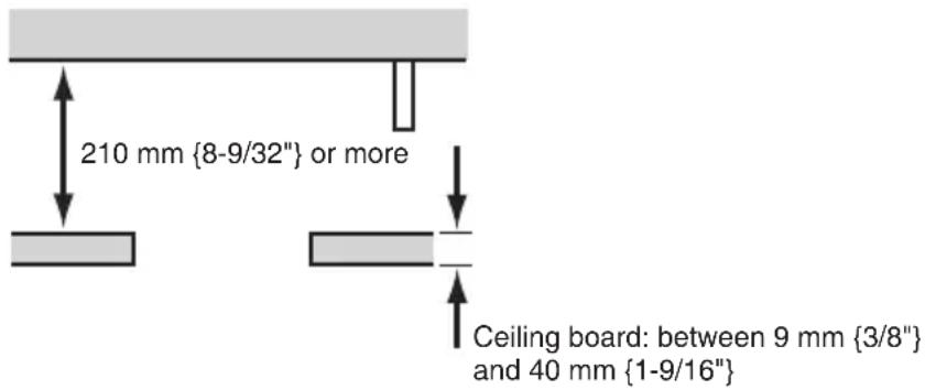
The thickness of the ceiling board for installation can range between 9 mm 3/8" and 40mm1 - 9 / 16" .
Avoid installing in the following locations.
Locations where it may get wet from rain or water splash (not only outdoor)
Locations where a chemical agent is used such as a swimming pool
Locations subject to steam and oil smoke such as a kitchen
Locations near flammable gas or vapor
Locations where radiation or x-ray emissions are produced
Locations subject to strong magnetic field or radio waves
Locations where it may be damaged by briny air such as seashores
- Locations where the temperature is not within -10^ - + 50^ {14°F - 122°F}.
- Locations subject to vibrations (This product is not designed for on-vehicle use.)
-
Locations where the temperature may rapidly change such as the peripheral areas of the air outlets of air conditioners or doors facing outside. (In case of installing the camera in such locations, the dome cover may become foggy or condensation may be caused on the cover.)
-
The screws and bolts must be tightened with an appropriate tightening torque according to the material and strength of the installation area. After tightening the screws or bolts, perform visual check to ensure tightening is enough and there is no backlash.
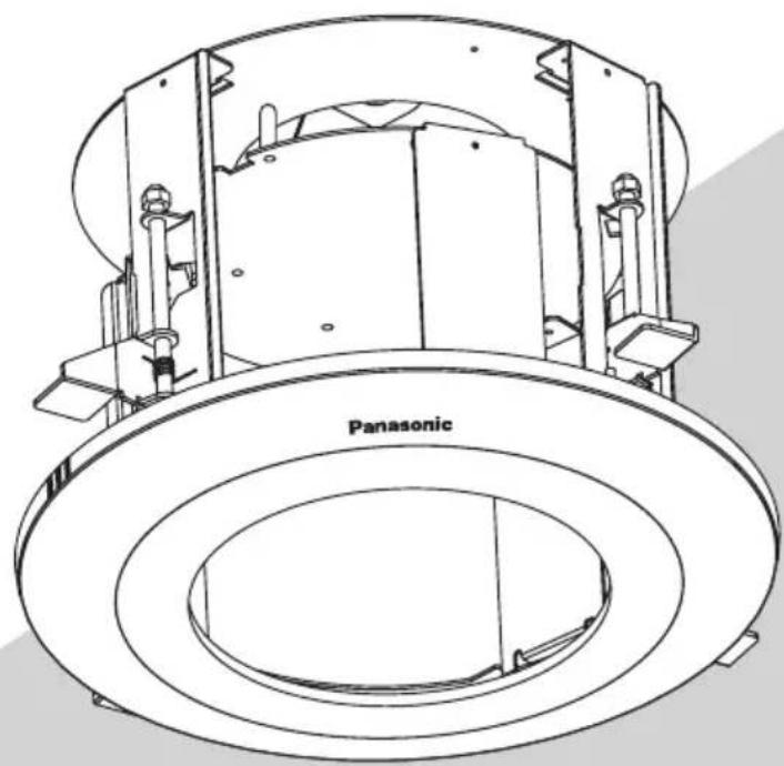
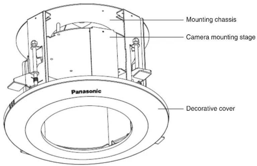
Major Operating Controls
Installations
Be sure to read "Precautions" before installation. The Installation Guide of the camera shall be read as well.
Put Template A (accessory) against the 1. ceiling and make a hole.
Make 4 holes of 12mm1 / 2^ in diameter.①
Remove the center part from the tem- ② plate.
Make a hole of 220 mm {8-43/64"} in ③ diameter.
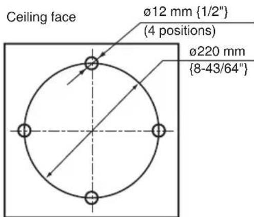
Template A
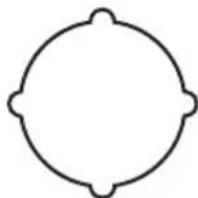
- 1 The hole shape is shown below.
*2 [For those concerned with the direction of the brand logo]
In order to set the position of the brand logo on the decorative cover you installed in Step 14 at the 12mm hole, you must perform the required operations during Step ①.
Perform Step ① to make sure the desired brand logo direction matches the "Brand logo side" setting on Template A. Also pay attention to this setting when performing Step 6 later.
Install two anchor bolts (M10 recommended) into the concrete ceiling.2.
Determine the anchor bolt length by use of Template B (accessory).①
Position the nut by use of Template B (accessory). (The distance between the bottom sur-② faces of the ceiling board and nut shall be 169 mm {6-21/32".})
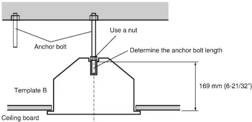
Install the anchor bolt in the center of the hole
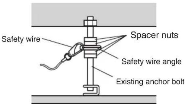
Note: If there is already an anchor bolt installed, the anchor bolt can be used as a second anchor bolt. Make sure that the distance between the 1st and 2nd anchor bolts is 1000 mm 39 - 3 / 8" or less before use.
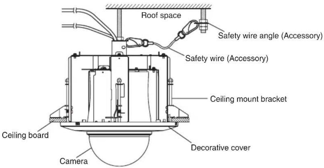
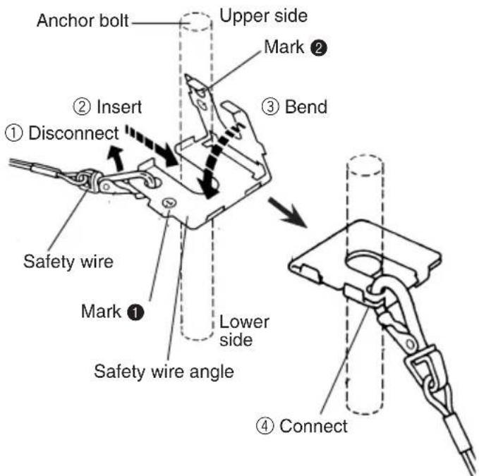
- Mount the safety wire angle (accessory) on the 2nd anchor bolt and connect the safety wire (accessory) to the angle.
Disconnect the safety wire from the ① safety wire angle.
Engage the face marked ② with the anchor bolt.
Bend the face marked ③
Connect the safety wire to the safety 4 wire angle again.
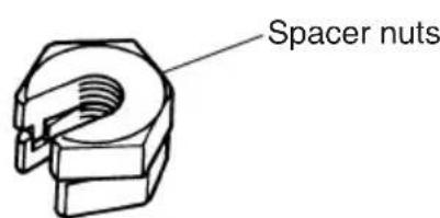
Note: To use the anchor bolt that was already installed, the use of 2 spacer nuts is helpful.
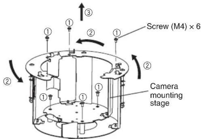
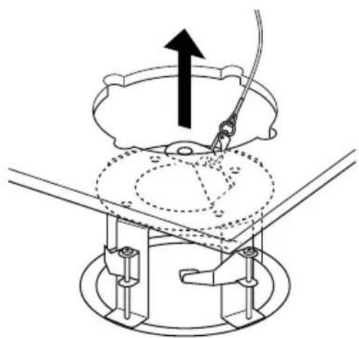
- Remove the camera mounting stage.
Remove the 6 screws (M4).①
Rotate the camera mounting stage ② a half-turn clockwise.
Lift the camera mounting stage and ③ remove it.
5. Connect the mounting chassis to another tip of the safety wire.
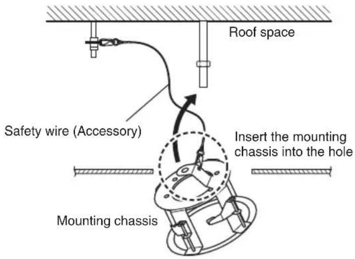
6. Insert the mounting chassis into the hole made in Step 1.
- [For those concerned with the direction of the brand logo]
The direction of the logo on the decorative cover you installed in procedure 14 is set according to the direction the mounting chassis is inserted. (see the below illustration)
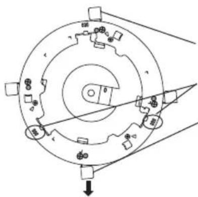
Ceiling board fixing bracket × 4
3 lines
Use the ceiling board fixing bracket as a guide
Align the brand logo with the ceiling board fixing bracket, which is nearly in the center of the 2 groups of 3 lines.
Direction of the brand logo on the decorative cover
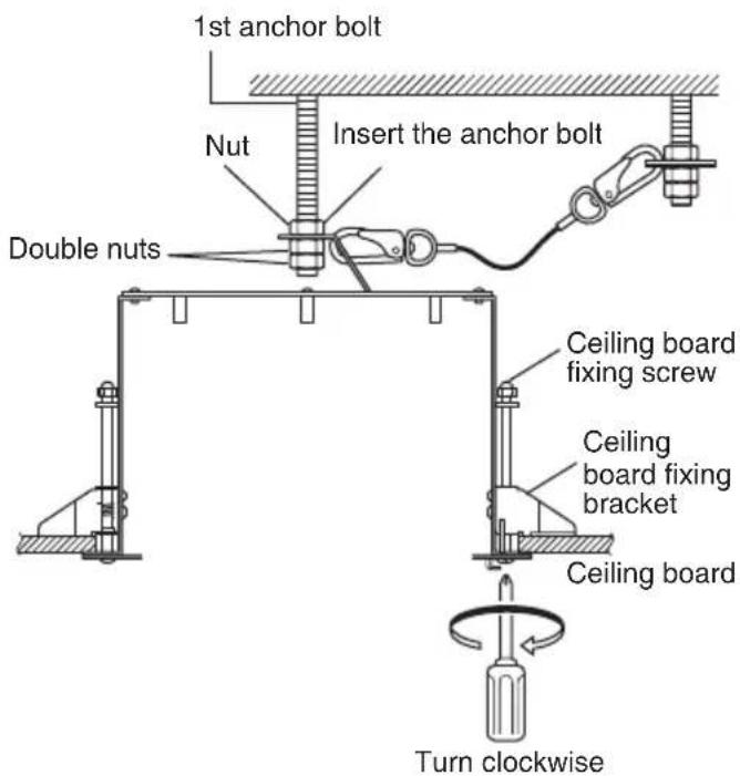
7. Secure the mounting chassis to the ceiling board with the ceiling board fixing screws (4 positions).
Engage the top of the mounting chas- ① sis with the 1st anchor bolt.
Secure the mounting chassis by turn- ② ing the ceiling board fixing screws clockwise.
Turning the ceiling board fixing screws clockwise provides ceiling board tightening between the bottom of the mounting chassis and ceiling board fixing bracket resulting in mounting chassis securing.
(Recommended tightening torque):
0.78 N·m {0.58 lbf·ft}
Secure the top of the mounting chas- ③ sis with double nuts.
Important: When securing this bracket on the ceiling, make sure that the four ceiling board fixing brackets are open as shown in the figure.
Prepare the cables.8.
Run the cables from the space of the mounting chassis.
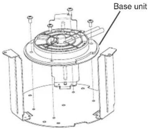
9. Attach the base unit or the camera mounting bracket to the camera mounting stage.
Insert and tighten the 4 screws (M4, accessory)
(Recommended tightening torque:
Which component to attach depends on the camera model. The base unit is a main unit component of the camera and the camera mounting bracket is an accessory of the camera.
The base unit is attached in figures shown in the following descriptions.
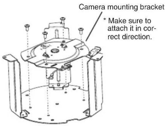
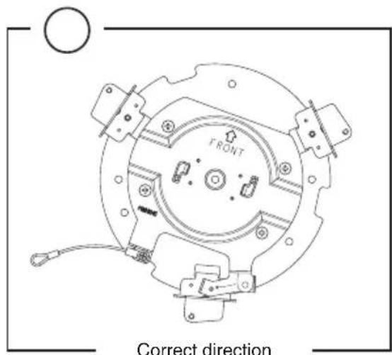
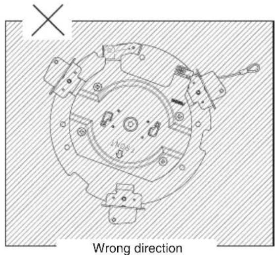
Important:
Make sure to attach the camera mounting bracket in correct direction. If you attempt to attach it in the wrong direction, some part of it will interfere with the camera mounting stage. Do not try to forcibly attach it as it may cause a failure or falling.
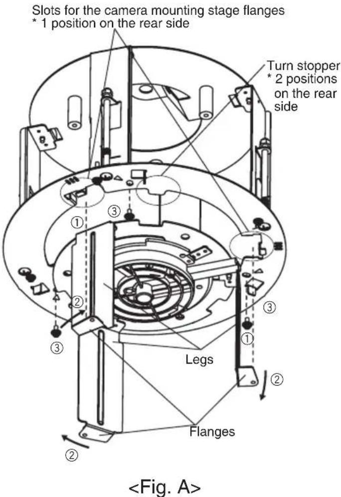
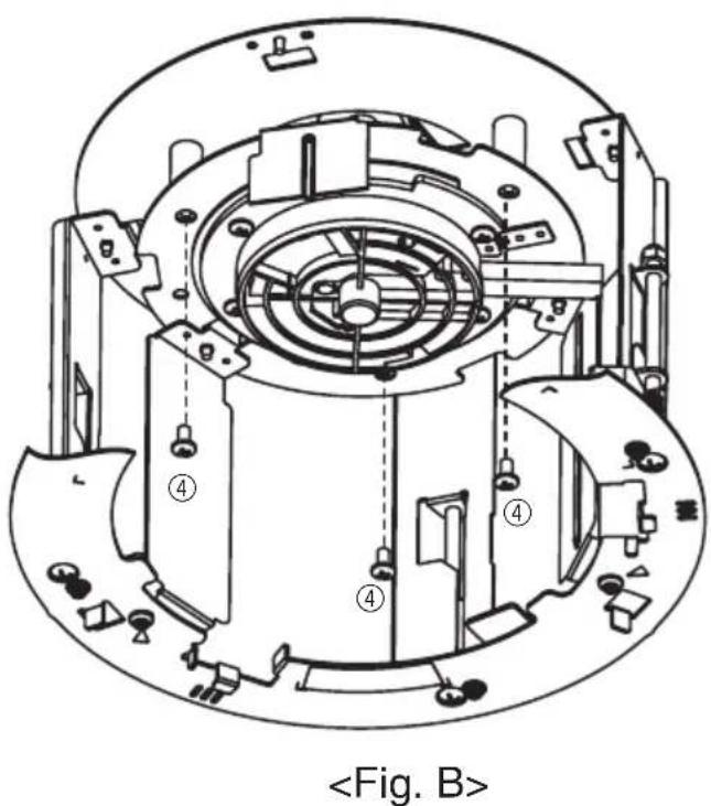
10. Mount the camera mounting stage on the mounting chassis.
Insert the camera mounting stage ① flanges (3 flanges) into the flange slots (3 slots) in the camera mounting chassis. Push it into the mounting chassis as far as it will go.
Once it is inserted into the mounting ② chassis, rotate it clockwise until it contacts the mounting chassis's turn stopper.
Caution: If it is difficult to move, grasp the flanges and legs and rotate.
Insert and tighten the 3 screws you ③ removed in Step 4. * Refer to
1.57 N · m {1.16 lbf · ft})
Insert and tighten the 3 screws you ④ removed in Step 4. * Refer to
1.57 N · m {1.16 lbf · ft})
Important: Do not let the cables be caught during installation work.
Connect the cables to the base unit or 11. the camera.
See the camera installation guide for information on how to connect the camera wires.
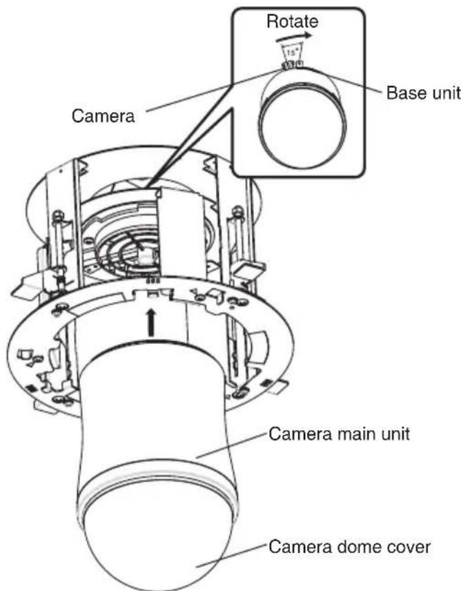
12. Mount the camera.
Attach the camera to the base unit or ① the camera mounting bracket you attached in Step 9.
Secure the camera with 1 piece of the ② camera fixing screw (supplied with the camera).
(Recommended tightening torque: 0.68 N·m {051 lbf·ft})
- See the camera installation guide for details on how to install the camera.
Important: Make sure you hold the camera main unit when you attach it. Holding the camera dome cover during attachment may cause damage to the cover.
Remove the protective sheet from the camera dome cover.13.
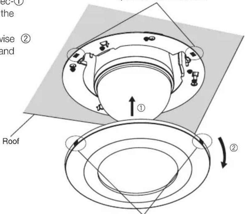
14. Mount the decorative cover.
Align the 3 lines on the side of the dec- ① orative cover with the 3 lines on the mounting chassis to attach.
Turn the decorative cover clockwise ② while pressing the cover upward and the cover is locked.
3 lines on the mounting chassis
1 position on the rear side
3 lines on the decorative cover
1 position on the rear side
Specifications
Ambient temperature: -10°C + 50°C {14°F - 122°F}
Dimensions: 245mm {9-29/64"} in diameter x 188.8 mm 7" in height
(including the decorative cover)
Weight: Approx. 1.2kg {2.65 lbs.}
Finish: Main body: Surface treatment steel sheet
Decorative cover: ABS resin with silver metallic coating
Standard Accessories
Operating Instructions (this book) 1 pc.
The following are for installation
Safety wire 1 pc.
Safety wire angle 1 pc.
Template A 1 sheet
Template B 1 sheet
Decorative cover 1 pc.
Screw (M4) 5 pcs. (inc. 1 spare screw)
VERSION FRANÇAISE
(FRENCH VERSION)
SOMMAIRE
Preface 13
Précautions 13
Principaux organes de commande 15
Installations 16
Caracteristiques techniques 23
Accessoires standards 23
Préface
Accessoires standards
Mode d'emploi (ce present document) 1 pc.
Panasonic System Communications Company of North America, Unit of Panasonic Corporation of North America
www.panasonic.com/business/
For customer support, call 1.800.528.6747
Three Panasonic Way, Secaucus, New Jersey 07094 U.S.A.
Panasonic Canada Inc.
5770 Ambler Drive, Mississauga, Ontario, L4W 2T3 Canada
(905)624-5010
www.panasonic.ca