
ALAN8001 S EURO - Walkie-talkie MIDLAND - Free user manual and instructions
Find the device manual for free ALAN8001 S EURO MIDLAND in PDF.

| Product Type | CB Walkie-Talkie (CB Radio) |
| Brand | Midland |
| Model | ALAN8001 S EURO |
| Dimensions (H x W x D) | 6 cm x 20 cm x 23.5 cm |
| Weight | 2.250 kg |
| Power Supply | 13.8 V DC nominal, ±10 % |
| Power Consumption (FM max transmit) | 4 A |
| Power Consumption (SSB max transmit) | 6 A |
| Power Consumption (squelched reception) | 0.6 A |
| Number of Channels | 40 |
| Modulation Modes | AM, FM, USB, LSB |
| Frequency Range | 26.965 to 27.405 MHz |
| Output Power (FM, SSB) | 4 W |
| Output Power (AM) | 1 W |
| Antenna Output Impedance | 50 Ω unbalanced |
| Antenna Connector | UHF SO-239 |
| Microphone | Dynamic low impedance (500 Ω) with PTT button |
| Built-in Speaker | 8 Ω |
| Operating Temperature | -10 °C to +55 °C |
| Maintenance and Cleaning | Clean with a dry soft cloth. Avoid solvents. |
| Safety | Install ground correctly, use the supplied fuse, do not expose to moisture. |
| Spare Parts and Repairability | Replaceable microphone. For other parts, contact customer service. |
Frequently Asked Questions - ALAN8001 S EURO MIDLAND
User questions about ALAN8001 S EURO MIDLAND
0 question about this device. Answer the ones you know or ask your own.
Ask a new question about this device
Download the instructions for your Walkie-talkie in PDF format for free! Find your manual ALAN8001 S EURO - MIDLAND and take your electronic device back in hand. On this page are published all the documents necessary for the use of your device. ALAN8001 S EURO by MIDLAND.
USER MANUAL ALAN8001 S EURO MIDLAND
ALAN 8001S EURO
_
| _
一
1
INDICE DEI CONTENUTI
Installazione 2
Posizione 2
Collegamenti 2
Mounting the Connection 2
Ignition Noise Interference 2
Antenna 2
Tuning the Antenna for Optimum SWR 3
External Speaker 4
Operation 4
Controls and Indicators 4
Front Panel 4
Real Panel 6
P.T.T. Microphone 6
Operating Procedure to Receive 6
Operating Procedure to Transmit 6
Receiving SSB signals 7
Roger Beep 8
Alternate Microphones and Installation 8
Specifications....11
INSTALLATION
LOCATION
Plan the location of the transceiver and microphone bracket before starting the installation. Select a location that is convenient for operation and does not interfere with the driver or passengers inside the vehicle. In cars, the transceiver is usually mounted below the dash panel, with the microphone bracket beside it.
MOUNTING THE CONNECTION
The transceiver is supplied with a universal mounting bracket. When mounting the bracket and radio inside your car, make sure it is mechanically strong. Also provide a good electrical connection to the chassis of the vehicle. To mount the transceiver, proceed as follows:
- After you have determined the most convenient location in your vehicle, hold the transceiver with mounting bracket in the exact location you have chosen. If nothing interferes with mounting it in the desired position, remove the mounting bolts. Before drilling the holes, make sure nothing will interfere with the installation of the mounting bolts.
- Connect the antenna cable plug to the standard receptacle on the rear panel. Most CB antennas are terminated with a PL 259 type plug and mate with the receptacle.
- Connect the red DC power input wire (with the fuse) to +13.8 Vdc. This wire extends from the rear panel. In automobile installation, +13.8 Vdc is usually obtained from the accessory contact on the ignition switch. This prevents the set being left on accidentally when the driver leaves the car, and also permits operating the unit without the engine running. Locate the accessory contact on most ignition switches by tracing the power wire from the AM broadcast receiver in the car.
- Connect the black lead to +13.8 Vdc. This is usually the chassis of the car. Any convenient location with good electrical contact (remove paint) may be used.
- Mount the microphone bracket on the right side of the transceiver or near the transceiver, using the two supplied screws. When mounting on a car, place the bracket under the dash so the microphone is readily accessible.
IGNITION NOISE INTERFERENCE
The use of a mobile receiver at low signal levels is normally limited by the presence of electrical noise. The primary source of noise in car installations is from the operated with vehicle engine turned off. The unit requires very little current and therefore will not significantly discharge the vehicle battery. In some installations, ignition interference may be high enough to make good communications impossible. The electrical noise may come from several sources. Many possibilities exist and variations between vehicles require different solutions to reduce the noise.
ANTENNA
A vertically polarized, quarter-wavelength whip antenna provides the most reliable operation and greatest range. Shorter, loaded-type whip antennas are more attractive, compact and adequate for applications where the maximum possible distance is not required. Also, the loaded whips do not present the problems of height imposed by a full quarter-wavelength whip. Mobile whip antennas utilize the metal body of the vehicle as a ground plane. When mounted at a corner of the vehicle they are slightly directional, in the
direction of the body of the vehicle. For all practical purposes, however, the radiation pattern is nondirectional. The slight directional characteristic will be observed only at extreme distances. A standard antenna connector (type SO 239) is provided on the transceiver for easy connection to a standard PL 259 cable termination. If the transceiver is not mounted on a metal surface, it is necessary to run a separate ground wire from the unit to a good metal electrical ground in the vehicle. When installed in a boat, the transceiver will not operate at maximum efficiently without a ground plate, unless the vessel has a steel hull. Before installing the transceiver in a boat, consult your dealer for information regarding an adequate grounding system and prevention of electrolysis between fittings in the hull and water.
TUNING THE ANTENNA FOR OPTIMUM SWR
Since there is such a wide variety of base and mobile antennas, this section will strictly concern itself to the various types of mobile adjustable antennas. Because the antenna length is directly related to the channel frequency, it must be tuned to resonate optimally all 40 channels of the transceiver. Channel 1 requires a longer antenna than Channel 40 because it is lower in frequency. Due to the various methods of adjusting antennas for proper SWR we have chosen what we think is the optimum method:
A. Antennas with adjustment screws (set screws).
- Start with the antenna extended and tighten the set screw lightly enough so that the antenna can be lightly tapped with your finger for easy adjustment.
- Set your transceiver to Channel 2.0. Press the PTT (push-to-talk) switch, and tap the antenna (making it shorter). The SWR meter will show a lower reading each time the antenna is tapped. By continuing to shorten the antenna you will notice the SWR reading will reach a low print and then start rising again. This means that you have passed the optimum point for Channel 20. Adjust the antenna and again follow the procedure above.
B. Antennas which must be cut to proper length.
- Follow the same procedure as above, but adjust the length by cutting 2/3 mm increments until a good match is obtained.
- Be very careful not to cut too much at a time, as once it is cut, it can no longer be lengthened.
- The whip is easily cut by filling a notch all the way around and breaking the piece off with pliers.
If you are having difficulties in adjusting your antenna, check the following:
A. All doors must be closed when adjusting the antenna.
B. Make sure the antenna base is grounded.
C. Check your coaxial cable routing (it may be pinched when routed into the car).
D. Try a different location on your car (keeping in mind the radiation pattern you wish).
E. Is the antenna perfectly vertical?
F. Try a different location in your neighbourhood. Stay away from large metal objects when adjusting (metal telephone or light posts, fences etc.)
WARNING: The transceiver will operate into a SWR of 2 to 1 indefinitely and sustain a SWR of 20: 1 for a maximum of 5 minutes at rated operating conditions.
EXTERNAL SPEAKER
The external speaker jack (EXT. SPK.) on the rear panel is used for remote receiver monitoring. The external speaker should have 8 ohms impedance and be able to handle 4 watts at least. When the external speaker is plugged in, the internal speaker is disconnected.
OPERATION
CONTROLS AND INDICATORS
There are 18 controls and 4 indicators on the front panel of your transceiver.
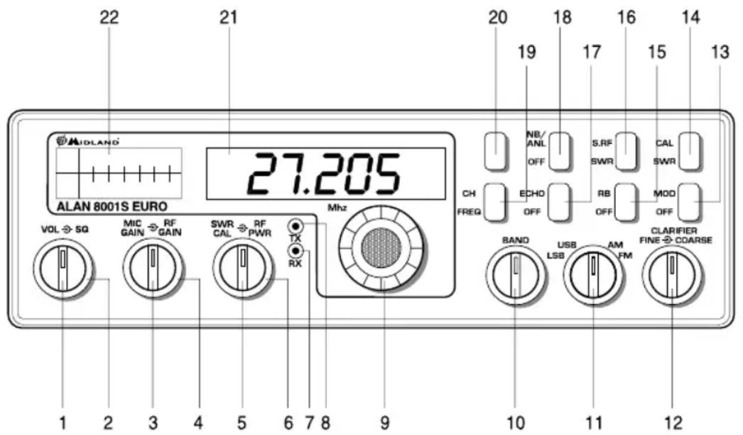
FRONT PANEL
- ON/OFF VOLUME (inner dual concentric). Turn clockwise to apply power to the unit and to set the desired listening level. During normal CB operation, the VOLUME control is used to adjust the output level obtained either at the transceiver speaker or the external speaker, if used.
- SQUELCH (outer dual concentric). This control is used to cut off or eliminate receiver background noise in absence of an incoming signal. For maximum receiver sensitivity it is desired that the control is adjusted only to the point where the receiver background noise or ambient background noise is eliminated. Turn fully counterclock-wise then slowly clockwise until the receiver noise disappears. Any signal to be received must now be slightly stronger than the average received noise. Further clockwise rotation will increase the threshold level which must be overcome by a signal in order to be heard. Only strong signals will be heard at a maximum clockwise setting.
- MIC GAIN (inner dual concentric). Adjust the microphone gain in the transmit mode.
- RF GAIN CONTROL (outer dual concentric). It reduces the gain of the RF amplifier under strong signal conditions.
- SWR CAL CONTROL (inner dual concentric). In order to achieve maximum radiated power and the longest range, it is important that your antenna is in good conditions,
properly adjusted and matched to your transceiver. The built-in SWR (standing wave ratio) meter lets you easily measure your operating antenna conditions. To operate this function, connect your antenna to the output connector. Select a channel near the middle of the band such as 21 or the channel you plan to use most frequently. Set the 16 switch on the SWR position, and the 14 switch on the SWR CAL position. Press and hold the microphone push-to-talk button and using the SWR CAL control, adjust the meter indicator on the CAL position. Then, without releasing the P.T.T. button, set the 14 switch on the OFF position and read the SWR indicated. The number 1 should be the ideal value. Generally speaking, readings up to 3 are acceptable, but over 3 indicates that you are losing radiated power and antenna adjustment may be necessary.
- RF POWER CONTROL (outer dual concentric). This control enables you to adjust the RF output power continuously over the range of 1 watt through 4 watts (SSB).
- RX INDICATOR. This indicator will be illuminated when the unit has been set in RX mode.
- TX INDICATOR. This indicator will be illuminated when the unit has been set in TX mode.
- CHANNEL SELECTOR. This switch selects anyone of the forty Citizens Band channels desired. The selected channel appears on the LED readout directly above the Channel Selector knob.
- NOT USED.
- MODE (FM/AM/USB/LSB) SWITCH. This switch is used to select the LSB, USB, AM, FM mode of operation. Unless the station with which communication is desired is equipped with SSB, the AM or FM mode is normally used. The mode switch changes the mode of operation of both transmitter and receiver simultaneously. Turn to "Receiving SSB signals" for a further explanation of single sideband.
- CLARIFIER. This control allows variation of the receiver operating frequencies above and below the assigned frequency. Although this control is intended primarily to tune in SSB signals, it may be used to optimize AM/FM signals as described in the Operating Procedure paragraphs. Coarse operates both TX/RX but Fine only in RX.
- MODE/OFF SWITCH. In MOD. position, the meter will show the modulation percentage, while in OFF position it will show the RF output power.
- SWR CAL/OFF SWITCH. This control, when in SWR/CAL position, is used to tune the SWR-meter.
- ROGER BEEP SWITCH. When this switch is placed in the ROGER BEEP position, your radio automatically transmits the audio signal at the end of your transmission. The listener can note easily your transmission is over through the signal.
- S-RF/SWR SWITCH. When set in S-RF position, the meter in RX mode shows the intensity of the received signal; during TX mode it shows the output power. In SWR position, it allows to measure the SWR value after tuning.
- ECHO SWITCH (OPTIONAL). Set this switch to ECHO when you desired to add an ECHO effect to your transmitting voice. This switch has no effect on receiving.
- NB/ANL-OFF SWITCH. In NB/ANL position, it activates the automatic noise limiter and operates as a filter; in OFF position it deactivates the function.
- FREQ-CHANNEL SWITCH. In FREQ position, this control activates the frequency meter; in CHANNEL position, the 2 digits indicate the selected channel.
- NOT USED.
- DISPLAY FREQUENCY METER. It shows the operating frequency and the selected channel.
- INDICATOR. This meter indicates the received signal strength, the SWR level, the transmitter RF output power, the TX modulation percentage; furthermore it allows the SWR-meter tuning.
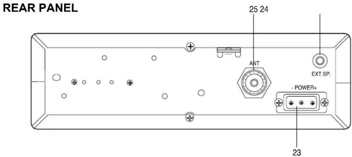
- POWER SUPPLY. Accepts 13.8 VDC power cable with built-in fuse to be connected.
- EXT SP. Accepts 4 to 8 ohm, 5 watt external speaker to be connected. When external speaker is connected to this jack, the built-in speaker is automatically disconnected.
- ANTENNA. Accepts 50 ohm coaxial cable with a PL-259 type plug to be connected.
PRESS-TO-TALK MICROPHONE
The receiver and transmitter are controlled by the press-to-talk switch on the microphone. Press the switch and the transmitter is activated, release switch to receive. When transmitting, hold the microphone 10 cm from the mouth and speak clearly in a normal "voice". The radios come complete with low-impedance (500 ohm) dynamic microphone. For installation instructions on other microphones, see the paragraph "ALTERNATE MICROPHONES AND INSTALLATION".
- Be sure that power source, microphone and antenna are connected to the proper connectors before going to the next step.
- Turn the unit on by tuning the VOL control clockwise on your transceiver.
- Set the VOLUME for a comfortable listening level.
- Set MODE switch (11) to the desired mode.
- Listen to the background noise from the speaker. Turn the SQUELCH control slowly clockwise until the noise just disappears (no signal should be present). Leave the control at this setting. The SQUELCH is now properly adjusted. The receiver will remain quiet until a signal is actually received. Do not advance the control too far, or some of the weaker signals will not be heard.
- Set the CHANNEL switch to the desired channel.
- Set the RF gain control fully clockwise for maximum RF gain.
- Adjust the CLARIFIER control to clarify the SSB signals or to optimize AM/FM signals.
OPERATING PROCEDURE TO TRANSMIT
- Select the desired channel of transmission.
- Set the MIC GAIN control fully clockwise.
- If the channel is clear, depress the push-to-talk switch on the microphone and speak in a normal voice.
RECEIVING SSB SIGNALS
There are four types of signals presently used for communications in the Citizens Band: FM, AM, USB, and LSB. When the MODE switch on your unit is placed in the AM position, only standard double-sideband and in FM position, only frequency deviation, full carrier signals will be detected. An SSB signal may be recognized while in the AM or FM mode by its characteristic “Donald Duck” sound and the inability of the AM or FM detector to produce an intelligible output. The USB and LSB modes will detect upper sideband and lower sideband respectively, and standard AM signals. SSB reception differs from standard AM reception in that SSB receiver does not require a carrier or opposite sideband to produce an intelligible signal. A single-sideband transmitted signal consists only of the upper or the lower sideband and no carrier is transmitted. The elimination of the carrier from the AM signal helps to eliminate the biggest cause of whistles and tones heard on channels which make even moderately strong AM signals unreadable. Also, SSB takes only half of an AM channel, therefore two SSB conversations will fit into each channel, expanding the 40 AM channels to 80 SSB channels. The reduction in channel space required also helps in the receiver because only half of the noise and interference can be received with 100% of the SSB signal.
An SSB signal may be received only when the listening receiver is functioning in the same mode. In other words, an upper sideband signal (USB) may be made intelligible only if the receiver is functioning in the USB position. If a lower sideband (LSB) signal is heard when the receiver is in the USB mode, no amount of tuning will make the signal intelligible. The reason for this may be understood if you consider that when modulation is applied to the transmitter's microphone in the USB mode, the transmitter's output frequency is increased whereas in the LSB mode the transmitter's output frequency is decreased. The result in listening to the receiver is that when the MODE switch is in the proper position (either USB, or LSB), a true reproduction of single tone of modulation will result, and if the tone is increased in frequency (such as a low-pitched whistle a high-pitched whistle) you will hear the increase in the output tone of the receiver.
If the incorrect mode is selected, an increase in tone of a whistle applied to the transmitter will cause a decrease in the resultant tone from the receiver. Thus when a voice is used in place of a whistle or tone, in the proper listening mode the voice will be received correctly whereas in the incorrect mode, the voice will be translated backwards and cannot be made intelligible by the voice lock control. When listening to AM transmission, a correct sideband is heard in either mode since both upper and lower sidebands are received.
Once the desired SSB mode has been selected, frequency adjustment may be necessary in order to make the incoming signal intelligible, the CLARIFIER control allows the operator to vary frequency above and below the exact-center frequency of the received signal. If the sound of the incoming signal is high or low pitched, adjust the operation of the CLARIFIER. Consider it as performing the same function as a phonograph speed control. When the speed is set too high, voices will be high-pitched and if set too low, voices will be low-pitched.
Also, there is only one correct speed that will make a particular record produce the same sound that was recorded. If the record is played on a turntable that rotated in the wrong direction (opposite sideband) no amount of speed control (CLARIFIER) will produce an intelligible sound. An AM signal received while listening in one of the SSB modes will produce a steady tone (carrier) in addition to the intelligence, unless the SSB receiver tuned to exactly the same frequency by the CLARIFIER control.
ROGER BEEP
When your transceiver is in normal operation, your radio automatically trasmits the audio signal at the end of your transmission. The listener can note easily that your transmission is over through the signal. Please note that this ROGER BEEP transmits 0.15-second at the moment PRESS-TO-TALK SWITCH KNOB is turned off.
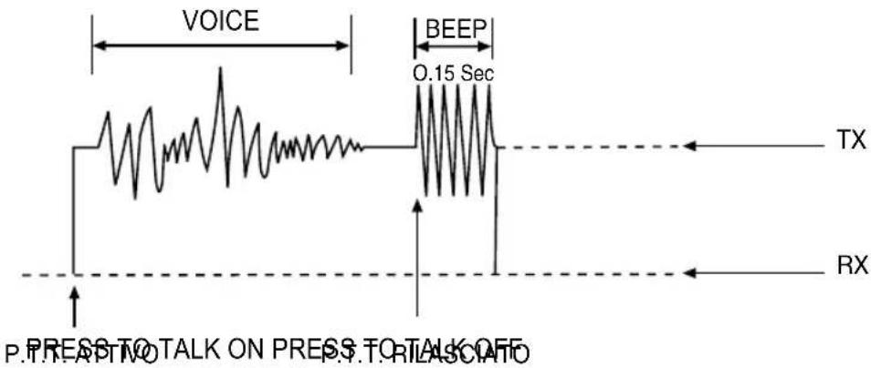
Fig.1.
ALTERNATE MICROPHONES AND INSTALLATION
For best results, the user should select a low-impedance dynamic type microphone or a transistorized microphone. Transistorized type microphones have a low output impedance characteristic. The microphones must be provided with a four-lead cable. The audio conductor and its shielded lead comprise two of the leads. The fourth lead is for receiving control, and third is for transmitting control. The microphone should provide the functions shown in the chart below.
4 WIRE MIC CABLE
| Pin Number Mic Cable Lead | |
| 1 Audio Shield | |
| 2 Audio Lead | |
| 3 Transmit Control | |
| 4 Receive Control | |
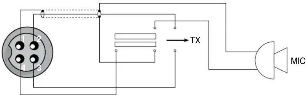
Fig. 2. Your transceiver microphone diagram
If the microphone to be used is provided with pre-cut leads, they must be revised as follows.
- Cut leads so that they extend 12 mm beyond the plastic insulating jacket of the microphone cable.
- All leads should be cut to the same length. Strip the ends of each wire 3 mm and tin exposed wire.
Before beginning the actual wiring read carefully the circuit and wiring information provided with the microphone you select. Use the minimum head required in soldering the connections. Keep the exposed wire lengths to a minimum to avoid shorting when the microphone plug is reassembled.
PIN BENERTACLE
A. MICROPHONE CONNECTOR ASSEMBLY
natural_image
Technical line drawing of a mechanical component with threaded ends and a central shaft (no text or symbols)B. CONNETOREDE MONEGONO, DISMENATED PER WIRABLAGGIO
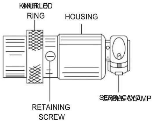
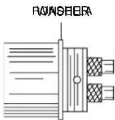
Fig. 3. Microphone plug wiring
- Remove the retaining screw.
- Unscrew the housing from the pin receptacle body.
- Loosen the two cable clamp retainer screws.
- Feed the microphone cable through the housing, knurled ring and washer as shown.
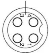
- The wires must now be soldered to the pins as indicated in the above wiring tables. If a vise or clamping tool is available it should be used to hold the pin receptacle body during the soldering operation, so that both hands are free to perform the soldering. If a vise or clamping tool is not available, the pin receptacle body can be held in a stationary position by inserting it into the microphone jack of the front panel. The numbers of the pins of the microphone plug are shown in Fig.4 as viewed from the back of the plug. Before soldering the wire to the pins, pre-tin the wire receptacle of each pin of the plug.
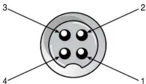
Fig.4 Microphone plug pin numbers viewed from rear of pin receptacle.
Be sure that the housing and the knurled ring of Fig. 3 are pushed back onto the microphone cable before starting to solder. If the washer is not captive to the pin receptacle body, make sure that it is placed on the threaded portion of the pin receptacle body before soldering. If the microphone jack is used to hold the pin receptacle during the soldering operation, best results are obtained when the connections to pin 1 and 3 are made first and then the connections to pins 2, 4. Use a minimum amount of solder and be careful to prevent excessive solder accumulation on pins, which could cause a short between the pin and the microphone plug housing.
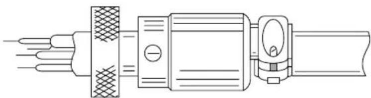
- When all soldering connections to the pins of the micro phone plug are complete, push the knurled ring and the housing forward and screw the housing onto the threaded portion of the pin receptacle body. Note the location of the screw clearance hole in the plug housing with respect to the threaded hole in the pin receptacle body. When the housing is completely threaded into the pin receptacle body, a final fraction of a turn either clockwise or counterclockwise may be required to align the screw hole with the threaded hole in the pin receptacle body. When these are aligned, the retaining screw is then screwed into the place to secure the housing to the pin receptacle body.
- The two cable clamp retainer screws should now be tightened to secure the housing to the microphone cord. If the cutting directions have been carefully followed, the cable clamp should secure to the insulating jacket of the microphone cable.
- Upon completion of the microphone plug wiring, connect and secure the microphone plug in the transceiver.
SPECIFICATIONS
| GENERAL | |
| Channels 40 CH/AM/FM/USB/LSB | |
| Frequency Range 26.965 ÷ 27.405 | |
| Frequency Control Phase Lock Loop (PLL) synthesizer | |
| Frequency Tolerance | 0.005 |
| Frequency Stability 0.001% | |
| Operating Temperature Range -10°C to + 55°C | |
| Microphone Plug-in dynamic with push-to-talk switch and coiled cord | |
| Input Voltage 13.8 V DC nominal | ± 10% |
| Current consumption Transmitter: | FM full mod., 4A -SSB PEP output, 4A Receiver: Squelched, 0.6A -Maximum audio output, 1.2A |
| Size 6 cm (H) x 20 cm (W) x 23.5 cm(D) | |
| Weight | 2.250 Kg |
| Antenna Connector | UHF, SO 239 |
| Meter (3-in-1) | Illuminated; indicates relative output power, received signal strength and SWR. |
| Duty cycle | 5/5/90 |
| TRANSMITTER | |
| Power Output | SSB: 4 W - FM: 4W - AM: 1W |
| Modulation | AM/FM/SSB |
| Intermodulation | SSB 3rd order, more than -25 dB |
| Distortion | 5th order, more than -35 dB |
| SSB Carrier Suppression | 55 dB |
| Unwanted Sideband | 50 dB |
| Frequency Response | AM and FM: 300 Hz to 3000 Hz |
| Output Impedance | 50 Ohms, unbalanced |
| Output Indicators | Meter shows relative RF output power and SWR. Transmit LED glows red when transmitter is working |
| RECEIVER | |
| Sensitivity | SSB: 0.25 μV for 10 dB (S+N)/NAM: 0.6 μV for 20 dB (S+N)/NFM: 0.6 μV for 20 dB (S+N)/N |
| IF Frequency AM/FM: 10.695 MHz 1st IF,455 kHz 2nd IF - SSB: 10.695 MHz | |
| Adjacent-Channel Rejection | 60 dB AM/FM & 70 dB SSB |
| RF Gain Control | 45 dB adjustable for optimum signal reception |
| Automatic Gain Control (AGC) | Less than 10 dB change in audio output for inputs from 10 to 100.000 microvolts |
| Squelch | Adjustable; thereshold less than 0.5 μV |
| ANL | Switchable |
| Clarifier Range | Coarse (RX) ±5 KHz; Fine (RX) ±1 KHz |
| Audio Output Power | 4 watts into 8 ohms |
| Frequency Response | 300 ÷ 3 KHz |
| Built-in Speaker | 8 ohms, round |
| External Speaker (Not Supplied) | 8 ohms; disables internal speaker when connected |
_
| _
一
1
INHALTSVERZEICHNIS
FRONTPLATTE
B. CONNETTORE DELIMPHADON, MONTATIOPER IL CABLAGGIO
Fig.3. Câblage microphone
PAINEL FRONTAL
natural_image
Technical line drawing of a mechanical device with multiple leads and a central shaft (no text or symbols)B. CONNETTOREDED MICROFONDE,ESMONTATOR PARA LACABLAGGIO
Fig. 3. Cablagem do fio do microfone
ΜΠΡΟΣΤΙΝΟ ΜΕΡΟΣ
The World in Communication

- ALAN 8001S EURO
- INDICE DEI CONTENUTI
- Installazione 2
- Operation 4
- Specifications....11
- INSTALLATION
- LOCATION
- MOUNTING THE CONNECTION
- IGNITION NOISE INTERFERENCE
- ANTENNA
- TUNING THE ANTENNA FOR OPTIMUM SWR
- Antennas with adjustment screws (set screws).
- Antennas which must be cut to proper length.
- EXTERNAL SPEAKER
- OPERATION
- CONTROLS AND INDICATORS
- FRONT PANEL
- PRESS-TO-TALK MICROPHONE
- OPERATING PROCEDURE TO TRANSMIT
- RECEIVING SSB SIGNALS
- ROGER BEEP
- ALTERNATE MICROPHONES AND INSTALLATION
- INHALTSVERZEICHNIS
- FRONTPLATTE
- PAINEL FRONTAL
- ΜΠΡΟΣΤΙΝΟ ΜΕΡΟΣ
Brand : MIDLAND
Model : ALAN8001 S EURO
Category : Walkie-talkie