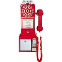
CR56 - Telephone Crosley - Free user manual and instructions
Find the device manual for free CR56 Crosley in PDF.


| Product Type | Retro Rotary Dial Phone |
| Brand | Crosley |
| Model | CR56 |
| Category | Desk/Wall Phone |
| Power | Telephone line (RJ11) |
| Dialing Modes | Tone (TONE) or Pulse (PULSE) |
| Redial Function | Last number redial button |
| Ringer Control | On/Off on back of phone |
| Earpiece Volume Adjustment | LOW/HI Selector |
| Built-in Piggy Bank | Coin slot with unlocking key |
| Line Cord Length | 7 feet (approximately 2.1 m) |
| Handset Cord | Coiled, detachable |
| Included Accessories | Handset, base unit, cords, 2 screws with wall anchors, 4 rubber feet, mounting template |
| Installation Options | On desk, on wall jack or wall mount with anchors |
| Electrical Safety | Polarized plug, do not expose to water |
| Maintenance | Clean with a dry cloth, no liquids |
| Repairability | Repair by qualified personnel only |
| Certifications | FCC Part 15 Class B, EU Directive 2014/53/EU |
| RF Safety Distance | 20 cm between the radiator and the body |
Frequently Asked Questions - CR56 Crosley
User questions about CR56 Crosley
0 question about this device. Answer the ones you know or ask your own.
Ask a new question about this device
Download the instructions for your Telephone in PDF format for free! Find your manual CR56 - Crosley and take your electronic device back in hand. On this page are published all the documents necessary for the use of your device. CR56 by Crosley.
USER MANUAL CR56 Crosley
Questions, problems, missing parts?
Before returning to the store, call Customer Service
8 a.m. - 6 p.m., EST, Monday - Friday
1-888-CROSLEY
www.crosleyradio.com
Safety Instructions
Read and understand this entire manual before using this product. Keep these instructions for future reference.
- Do not use this product near water.
- This product should be operated only by the type of power source indicated on the marking label or in this instruction manual.
- Do not defeat the safety purpose of the polarized plug. A polarized plug has two blades with one blade wider than the other. This plug will fit into the power outlet only one way. If you are unable to insert the plug fully into the outlet try reversing the plug. If the plug should still fail to fit, contact your electrician.
- Protect the power cord from being walked on or pinched particularly at plugs, convenience receptacles, and the point where they exit from the product.
- Do not overload wall outlets, extension cords, or integral convenience receptacles as this can result in a risk of fire or electric shock.
- Never push objects of any kind into this product through openings as they may touch dangerous voltage points or short-out parts that could result in a fire or electric shock. Never spill liquid of any kind on the product.
- Do not attempt to service this product yourself as opening or removing covers may expose you to dangerous voltage or other hazards. Refer all servicing to qualified service personnel.
- Changes or modifications to this unit not expressly approved by the party responsible for compliance could void the user's authority to operate the equipment.
- Do not use attachments not recommended by the product manufacturer as they may cause hazards.
- A product and cart combination should be moved with care. Quick stops, excessive force, and uneven surfaces may cause the product and cart combination to overturn.
- Slots and openings in the cabinet are provided for ventilation and to ensure reliable operation of the product and to protect it from overheating. Do not block or cover these openings.
- Unplug the product during lightning storm or when unused for long periods of time.
Items in this package
Before throwing away any packaging materials, please check thoroughly and make sure you find the following items that come along with this package:
- Telephone handset
2 Screws with wall anchors
Handset coil cord - 4 Rubber spacer pads
- Telephone body
- Wall Template
- 7 Foot line cord
Please contact Crosby customer service if there is any accessory missing from the package. Retain the original packaging materials for exchange or return purposes.
Product Description
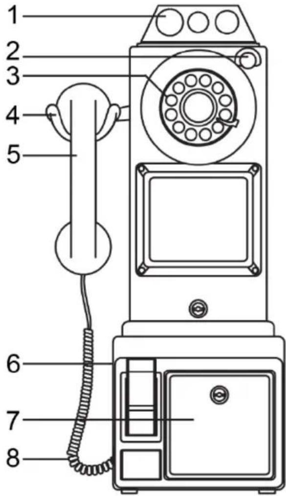
- Coin Slot
- Redial Button (Coin Release)
- Dial
- Handset Cradle
- Handset
- Handset Cord Jack
- Coin box
- Handset Cord
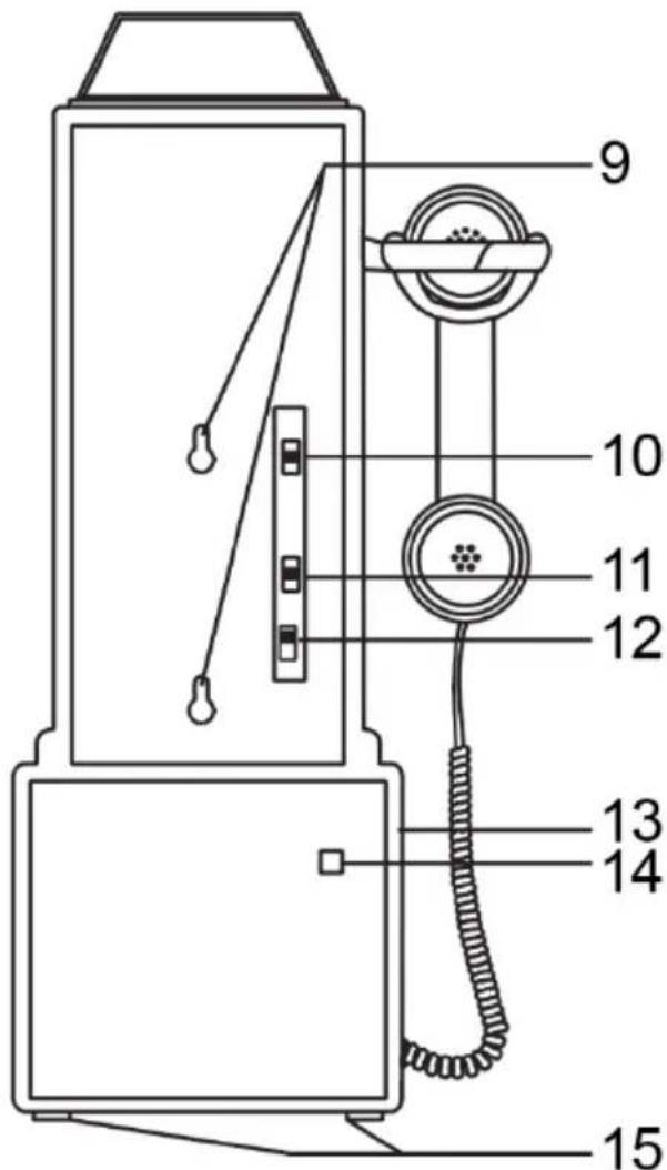
- Mounting Holes
- Ringer Control
- Dial Mode
- Receiver Volume
- Headset Cord Jack
- Channel Line Cord Jack
- Space Pads
Setup
Dial Mode
Locate the DIAL MODE switch on the rear of the telephone body. Slide the switch to TONE unless you have Dial-Pulse (Rotary) telephone service in your area in which case, slide the switch to the PULSE position.
Ringer Control
The RINGER CONTROL switch on the rear of the telephone allows you to turn the ringer ON or OFF. You can still make or receive calls with the ringer in OFF position, however, you will not hear the incoming ring.
Receiver Volume
The RECEIVER VOLUME CONTROL switch, located on the rear of the telephone body, allows you to adjust the volume of the receiver earphone from LOW and HI.
Handset Cord
To assemble, insert the end of the handset cord into the HANDSET CORD JACK located on the left side of the telephone body.
Installation
Modular Wall Jack
To install the telephone directly on a modular wall jack:
- Connect the line cord to the LINE CORD jack on rear of telephone body.
- Tuck the line cord into the channel on the back of the phone.
- Peel and stick the rubber pads on the back side of the phone in the 4 corners.
- Hold the telephone body up next to the modular jack and plug the line cord into this jack.
- Tuck the excess line cord into the recess provided on the back of the phone.
- Line up the mounting holes of the telephone body with the mounting studs (screw heads) on the modular jack or wall.
- Push the telephone body against the wall jack and gently pull down.
Wall
If you are not mounting directly onto a modular wall jack, proceed as follows:
- Install the line cord into the LINE CORD jack on the back of the telephone. If the desired location is farther than 7-foot from a wall jack, you will have to obtain a longer line cord available at most hardware stores.
- Place the provided TEMPLATE against the wall in the position desired.
-
Mark the wall by poking either a pen or pencil through the indicated spots on the template.
-
If there is no stud at this location, it will be necessary to install the provided wall anchors. Drill a small pilot hole at the marked locations. Tap the anchors into the holes. Then insert screws, but DO NOT TIGHTEN. Leave the screw heads protruding about 14 inch.
- If there is a stud at this location, simply install the two screws into the stud. Remember to leave screw head protruding.
- Telephone is then mounted according to procedure detailed in mounting to modular plug.
Note: If you encounter difficulty fitting the telephone body onto the screws, or the telephone wobbles when installed, either tighten or loosen the screws to adjust.
Table
- Connect the line cord to LINE CORD jack on the rear of the telephone body.
- Plug free end of line cord into nearest modular telephone jack.
To Install Wall Anchors
If the location, you have chosen to mount your telephone is a hollow wall without any beams you will have to use the included wall anchors.
To install, place the template against the wall where you wish to place your telephone. Mark the wall at the location of the two + on the template by pushing a pen or pencil through the template. Drill a 1/4" hole at each mark.
With a Phillips screwdriver, begin tightening the screw by turning it clockwise.
Stop turning when you feel firm resistance.
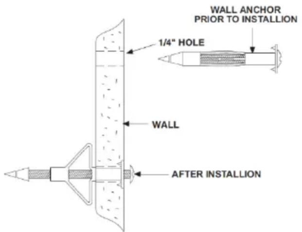
Turn the screw counterclockwise until the screw head is about 1/4 out of the wall.
Install the line cord at back of the telephone. Adjust the switches to your preference. Position the line cord through the slot on the bottom of the cabinet. Line up the holes with the two screws. Place the telephone onto these two screws and gently pull down.
This may require a little fine tuning until the phone is seated securely.
Operation
Making and Answering Calls
To get a dial tone or answer an incoming call, lift the handset.
To hang up, either replace the handset or simply press down the Handset Cradle.
To Redial
The last number dialed is automatically stored in the phone. To redial the last number, lift the handset and press the REDIAL (coin release) button.
Coinbox
Coins can be deposited into the COIN SLOTS located on the top of the telephone body. The coins will ring a bell and drop into the coin box. The coinbox may be opened by inserting the key and rotating.
Troubleshooting
No Dial Tone
- Make sure that all plugs are connected properly. Check the connections at the wall jack, the telephone body and the handset.
- Try another modular jack within your home which you know to be working properly.
Calls cannot be dialed or dialed slowly
- Check to make sure that the DIAL MODE switch is in the correct position for the type of service available in your area.
Telephone does not ring
- Check the Ringer Control switch is not set to OFF.
- If there are several telephones connected to the same line, try disconnecting some of the other telephones. Having too many telephones connected to the same line can cause low ringer volume or poor sound quality during calls.

KEY HOLE A
USE THIS TEMPLATE TO DETERMINE THE POSITION OF TELEPHONE ON WALL, AND WHERE TO LOCATE SCREW HOLES.
REMOVE TEMPLATE FROM WALL BEFORE INSERTING PLASTIC ANCHORS OR SCREWS
USE ONLY FOR WALL INSTALLATION OF TELEPHONE SET
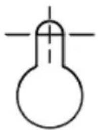
KEY HOLE B
FCC Statements
This device complies with part 15 of the FCC Rules. Operation is subject to the following two conditions:
(1) This device may not cause harmful interference, and
(2) this device must accept any interference received, including interference that may cause undesired operation.
Note: This equipment has been tested and found to comply with the limits for a Class B digital device, pursuant to part 15 of the FCC Rules. These limits are designed to provide reasonable protection against harmful interference in a residential installation. This equipment generates, uses and can radiate radio frequency energy and, if not installed and used in accordance with the instructions, may cause harmful interference to radio communications. However, there is no guarantee that interference will not occur in a particular installation. If this equipment does cause harmful interference to radio or television reception, which can be determined by turning the equipment off and on, the user is encouraged to try to correct the interference by one or more of the following measures:
- Reorient or relocate the receiving antenna.
- Increase the separation between the equipment and receiver.
- Connect the equipment into an outlet on a circuit different from that to which the receiver is connected.
- Consult the dealer or an experienced radio/TV technician for help.
Note: The Grantee is not responsible for any changes or modifications not expressly approved by the party responsible for compliance. such modifications could void the user's authority to operate the equipment.
The device has been evaluated to meet general RF exposure requirement.
To maintain compliance with FCC's RF exposure guidelines, the distance must be at least 20~cm between the radiator and your body, and fully supported by the operating and installation configurations of the transmitter and its antenna(s).
SIMPLIFIED EU DECLARATION OF CONFORMITY
Hereby, Modern Marketing Concepts Inc. dba Crosby Brands, declares that the radio equipment type is in compliance with Directive 2014/53/EU. The full text of the EU declaration of conformity is available at the following internet address: http://crosleybrands.com/euDoC
CROSLEY
CR56

- Safety Instructions
- Items in this package
- Product Description
- Setup
- Dial Mode
- Ringer Control
- Receiver Volume
- Handset Cord
- Installation
- Modular Wall Jack
- Wall
- Table
- To Install Wall Anchors
- Operation
- Making and Answering Calls
- To Redial
- Coinbox
- Troubleshooting
- No Dial Tone
- Calls cannot be dialed or dialed slowly
- Telephone does not ring
- FCC Statements
- SIMPLIFIED EU DECLARATION OF CONFORMITY
- CROSLEY
Brand : Crosley
Model : CR56
Category : Telephone