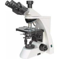
SCIENCE TRM 301 - Microscope BRESSER - Free user manual and instructions
Find the device manual for free SCIENCE TRM 301 BRESSER in PDF.


| Product type | Trinocular biological microscope |
| Brand | Bresser |
| Model | SCIENCE TRM 301 |
| Head | Trinocular, inclined, with interpupillary and diopter adjustment |
| Eyepieces | Wide field WF 10x, 20 mm field |
| Objectives | Plan-achromatic 4x/0.10, 10x/0.25, 40x/0.65, 100x/1.25 (oil) |
| Total magnification | 40x to 1000x |
| Illumination | Halogen with intensity control |
| Power supply | Mains 230 V AC, fuse 0.5 A / 250 V |
| Stage | Mechanical, orthogonal movements 75 mm |
| Condenser | Abbe N.A. 1.25, with iris diaphragm and height adjustment |
| Focusing | Coarse and fine focusing with safety lock |
| Observation | Bright field, Köhler illumination |
| Maintenance | Clean optics with a soft cloth moistened with alcohol or ether |
| Safety | Do not leave children unattended, store sharp accessories |
| Warranty | 2 years |
| Compliance | CE |
| Included accessories | Eyepieces, objectives, condenser, stage, immersion oil (not specified) |
Frequently Asked Questions - SCIENCE TRM 301 BRESSER
User questions about SCIENCE TRM 301 BRESSER
0 question about this device. Answer the ones you know or ask your own.
Ask a new question about this device
Download the instructions for your Microscope in PDF format for free! Find your manual SCIENCE TRM 301 - BRESSER and take your electronic device back in hand. On this page are published all the documents necessary for the use of your device. SCIENCE TRM 301 by BRESSER.
USER MANUAL SCIENCE TRM 301 BRESSER
Transmission-type Microscope
BRESSER Science TRM-301

CE
Do not dispose of electric equipment together with household waste material! In observance of European Directive 2002/96/EC on waste electrical and electronic equipment (WEEE) and its implementation in accordance with national law, electric equipment that have reached the end of its life must be collected separately and returned to an environmentally compatible recycling facility. Discharged batteries and damaged re-chargable batteries must be disposed of at special battery collection points. Information is available from your local disposal agent or local authority.
natural_image
Close-up of a black mechanical component with three cylindrical features and red directional arrows indicating rotation (no text or symbols)natural_image
Close-up of a mechanical optical device with labeled parts, showing internal components and no visible text or symbols.Abb. 5
natural_image
Close-up of a microscope with visible internal components and a circuit board (no text or symbols)Abb. 6
natural_image
Close-up of a white laboratory microscope with labeled components (no text or symbols visible)Abb. 7
natural_image
Close-up of a mechanical device with circular components and mounting holes (no visible text or symbols)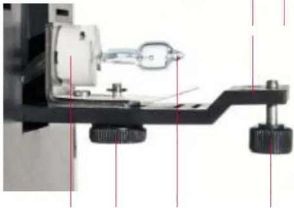
natural_image
Mechanical assembly diagram showing a motor, clamping mechanism, and adjustment knobs (no text or labels visible)Abb. 9
natural_image
Close-up of a black hexagonal electrical outlet with three slots and a red arrow pointing to the slots (no text or symbols visible)To work with this microscope, sharp and pointed aids are being used. Please take care that this microscope and its accessories are stored out of the reach of children. Let children only work with this microscope under an adult's supervision! Keep packing material (plastic bags etc.) away from children!
Table of Contents
I. Components
II. Technical Data / Included with Your Purchase
III. Observing Operation
IV. The Operations of Each Unit
V. Maintenance, EEC Conformity Explanation, Warranty
I. COMPONENTS
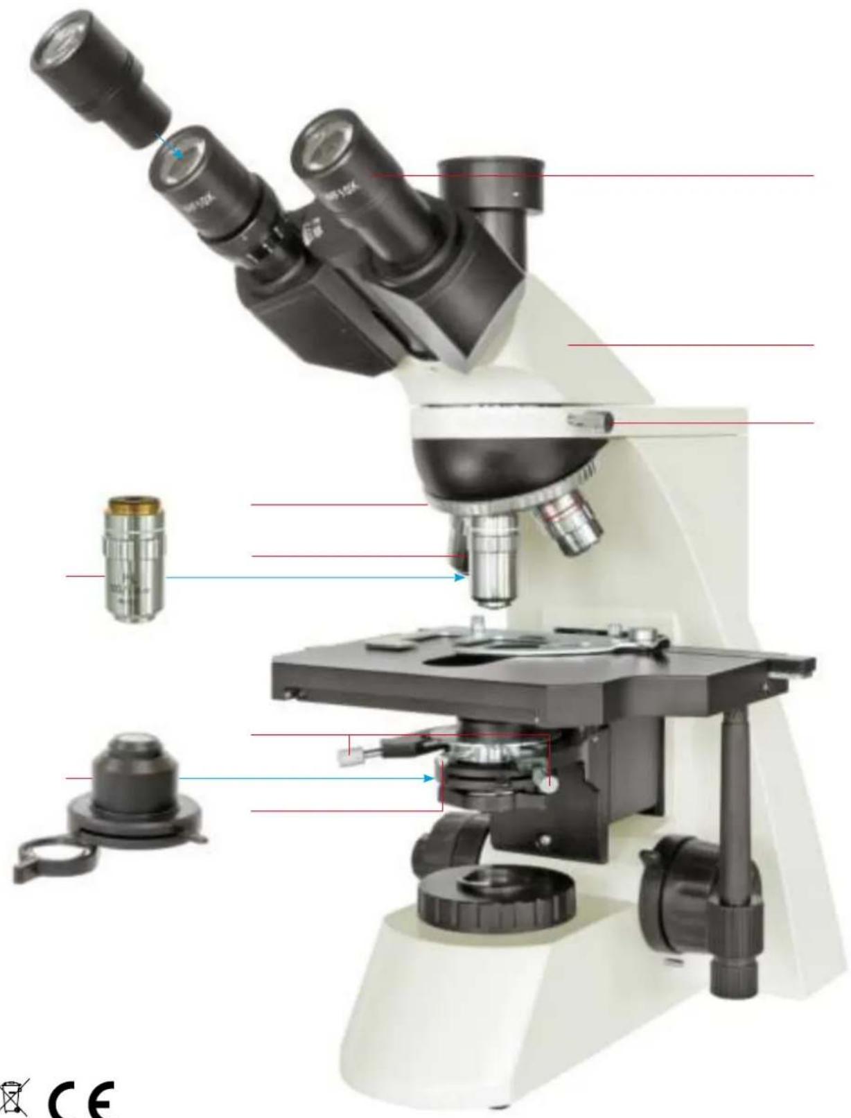
Fig. 1
Nosepiece
Condenser up-down knob
Knob for tensional adjustment of focusing
Coarse focusing knob
Fine focusing knob
Power switch
Brightness control knob
Auxiliary lens of condenser
Condenser holding screw
Condenser centering screw
Stage
Objective
Fig. 2
Eyepiece
Specimen holder
Condenser (with aperture diaphragm)
Field diaphragm and filter seat
Limit knob (up stop)
Fine focusing knob
Power supply
Fuse holder
Transversal adjustment knob
Longitudinal adjustment knob
Tube holding screw
Trinocular head
Fig. 3
Tube holding screw
Trinocular head
Eyepiece
Nosepiece
Objective
Condenser centering screw
Condenser holding screw
Condenser (with aperture diaphragm)
II. TECHNICAL DATA / INCLUDED WITH YOUR PURCHASE
| Eyepieces | ||||
| Eyepiece type Magnification Field of view | diameter / mm | Focal length f / mm | Remarks | |
| Wide field eyepiece (WF) 10x 20 25 | ||||
| WF eyepiece with crosshair 10x optional | ||||
Objectives
| Objective type Magnification Numerical aperture | NA | Working distanceWD / mm | |
| Planachromaticobjective | 4x 0.1 17.9 | ||
| 10x 0.25 8.8 | |||
| 40x 0.65 | 0.56 | ||
| 100x | 1.25 (oil) | 0.33 | |
Total magnification
| Objective: | 4x | 10x | 40x | 100x (oil) |
| Total magnification | ||||
| Eyepiece: | ||||
| 10x 40x | 100x | 400x | 1000x | |
traverse 75 mm.
adjustment.
III. OBSERVING OPERATION
- Press the power switch on the side „I“ in order to switch on the illumination.
- By turning the nosepiece, set the 10x objective into the operation position. Then focus the specimen, which is on the stage.
- Adjust the interpupillary distance and the diopter (for binocular observation).
- Adjust the up & down position of the condenser, the light control and the aperture diaphragm in order to get a satisfying luminal effect. When you watch with the 4x or 10x objective, bring down the condenser to get symmetrical light. When you watch with the 4x objective, put the auxiliary lens of condenser in observation position.
- When you interchange objectives, turn the nosepiece and refocus slightly with the fine focusing knob. When you use the 100x objective, be sure to put a drop of immersion oil between the objective and the specimen as well as between the condenser and the slide.
IV. THE OPERATIONS OF EACH UNIT
1. Adjustment of interpupillary distance (Fig. 4)
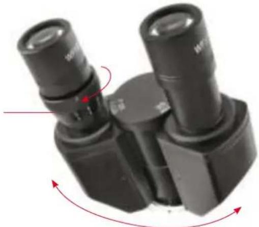
natural_image
Close-up of black mechanical components with red directional arrows indicating rotation or movement (no text or symbols visible)Fig. 4
Put the specimen on the stage and bring it into the exact focus. Adjust the interpupillary distance of the binocular viewing by "folding" the binocular tube (1) on the optical head, until the right and the left field of view can be composed to one.
2. Adjustment of diopter (Fig. 4)
Put the specimen on the stage. Turn the 40x objective to the working position. Firstly, observe at the right eyepiece with the right eye; adjust the coarse and fine focusing knob to image clearly. Secondly, observe at the left eyepiece with the left eye; adjust the diopter control (2) to image clearly.
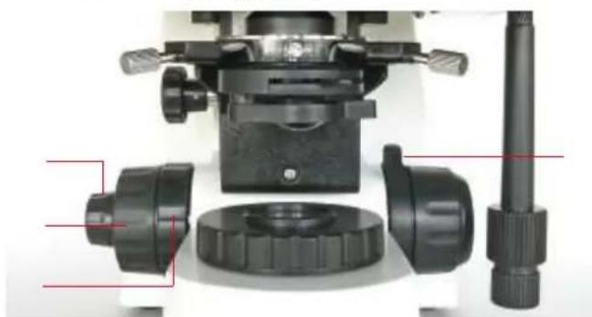
3. Coarse/Fine focusing (Fig. 5)
natural_image
Close-up of a microscope objective with labeled parts including lens, aperture, and adjustment knobs (no text or symbols visible)Fig. 5
The instrument uses a coaxial coarse/fine focusing mechanism. The knob for tensional adjustment of focusing (4) is used for adjusting the tension of the coarse focusing knob (3) to prevent the stage from naturally sliding down. The limit knob (1) prevents accidental contact between specimen and objective. After locking the limit knob (by turning up and fastening) at a chosen height of the stage, you cannot focus the object closer to the objective using the coarse focusing knob. So, the object is protected against damage. (2) is the fine focusing knob.
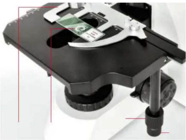
4. Stage (Fig. 6)
natural_image
Close-up of a microscope with visible internal components and a green circuit board (no text or symbols)Fig. 6
The convenient specimen holder (1) on the stage is used for holding the slide glass (2). The longitudinal (lengthwise) adjustment knob (3) and the transversal (cross) adjustment knob (4) are coaxial. The stage moves expediently.
5. Adjustable Abbe condenser (Fig. 7)

natural_image
Close-up of a microscope with labeled components (no text or symbols visible)Fig. 7
The condenser is moved up or down via turning the up-down knob (1). For centering, the condenser centering screws (7) are used. The condenser can be taken down easily if one unscrews the condenser holding screw (2). The place for a filter plate is on the filter seat (6).
6. Power switch and adjustable brightness (Fig. 7)
Turn on the power switch (3). Adjust the light control (4) until the image can be observed comfortably. Note: Don't let the light control at the position of maximum brightness for a long time. That reduces the life-span of the lamp.
7. Köhler illumination (Fig. 7)
The Köhler illumination is the optimal microscopic illumination and therefore standard for scientific research and microphotography. One gets it using the fixed field diaphragm and the height- and center-adjustable Abbe condenser:
a) Using the condenser up-down knob (1), move the condenser (Fig. 2, No. 3) to the highest position, right under the stage.
b) Turn on the power switch (3) and focus the object.
c) Shut the field diaphragm (Fig. 2, No. 4) as close as possible. If the image of the field diaphragm lies out of the field of view, move it into the field using the condenser centering screws (Fig. 1, No. 10).
d) Using the condenser up-down knob (1), change the height of the condenser, until the image of the field diaphragm is clear.
e) Using the condenser centering screws (Fig. 1, No. 10), center the image of the field diaphragm in the field of view.
f) Open the field diaphragm so widely, that its edge has only just left the field of view and this field is complete illuminated. It may be, that you have to center the condenser a little bit again. Now, adjust the aperture diaphragm, which is described in the next paragraph.
8. Aperture diaphragm (Fig. 8)
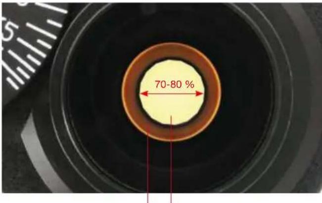
Fig. 8
The aperture diaphragm lever (Fig. 7, No. 5) can be turned in order to open or close the aperture diaphragm. Remove the eyepieces and watch through the eyepiece tube. For centering, the condenser centering screws (Fig. 7, No. 7) are used when the diaphragm image is eccentric with the objective pupil (1). Turn the aperture diaphragm lever for getting a good resolution and contrast perception. Usually, the diameter of the aperture diaphragm image (2), which has to be adjusted, is 70-80 percent of the objective pupil.
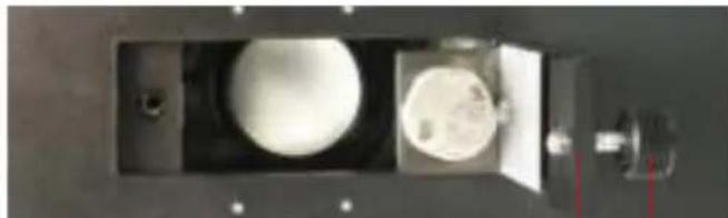
9. Exchange of the lamp (Fig. 9)
a) Switch off the power switch and pull out the plugs of the power cord from mains socket and from mains in at the microscope (Fig. 2, No. 7).
b) Incline the microscope, loose the fixing screw (3) of the lamp door on the middle part of the bottom and open the lamp door; so, you remove the lamp baseboard (1) from the bottom.
c) Pull out the old lamp (4) from the lamp base (5). Be careful, as the lamp may be hot!
d) Insert the new lamp (4) into the lamp base (5). Notice the properly touching; take care not to touch the lamp with bare fingers. E. g., use the protective envelope of the lamp or a tissue, in order to grasp the bulb.
e) Reinstall the lamp door (1) with lamp base board (5) on the bottom with the screw (3).
f) After mounting the lamp well, plug in the power cord, turn on the power switch, turn the objective lens into the light path, adjust the condenser upwards and downwards, and make light enter the view field. If the light spot is offset from the center of view, loose the screw (2) slightly and move the lamp base (5). Move the lamp spot into the center, then tighten up the screw (2) immediately.
natural_image
Close-up of a mechanical component with circular features and a central shaft (no visible text or symbols)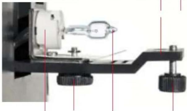
natural_image
Mechanical assembly diagram showing a component with springs and adjustment knobs (no text or symbols visible)Fig. 9
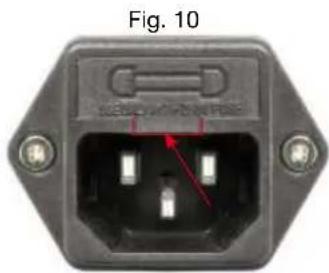
10. Exchange of the fuse (Fig. 10)
Switch off the power switch and pull out the plugs of the power cord from mains socket and from mains in at the micro-
natural_image
Close-up of an electrical outlet terminal with three leads and a red arrow pointing to one (no text or symbols on the main body)scope (Fig. 1, No. 7). Grip with a small screwdriver under the lug of the fuse holder (Fig. 10) and pull it carefully forward. Take out the fuse holder (Fig. 1, No. 8). Change the fuse. Install the fuse holder and plug again. The specification of fuse: 250 V, 0.5 A, F.
V. MAINTENANCE
1. Sweep the lens
Sweep the lens by lens tissue or soft fabric immersed with a mixed liquid of alcohol/ether. Clean the 100x oil objective from oil whenever you finish operating.
2. Clean the painted parts
The dust on the painted parts can be removed by gauze. For the grease spots, the gauze immersed slightly with aviation gasoline is recommended. Do not use organic solvents such as alcohol, ether or other thinner etc. for cleaning the painted parts or plastic components.
3. Avoid disassembling the microscope
Because of being a precise instrument, do not disassemble the microscope casually. That may cause serious damage to its performance.
4. Being not used
Cover the microscope with the dust cover (made of polyethylmethacrylate or polyethylene) and place it there,
where it is dry and mouldless. We suggest the storage of all objectives and eyepieces in a closed container with drying agent.
EEC CONFORMITY EXPLANATION
Bresser GmbH, resident in 46414 Rhede/Westf., Gutenbergstr. 2, Germany, explains the agreement with in the following specified EEC guidelines for this product:
EN 61326: 1997
EN 61000-3-2
Product description: Biological microscope
Model: BRESSER Science TRM-301
Rhede, July 20, 2007
Bresser GmbH
Helmut Ebbert
Managing director
WARRANTY
The period of warranty is 2 years, beginning on the day of purchase. Please keep the cash receipt as evidence of purchase. Devices which become defective during the warranty period can be returned to the dealer where the device was bought. The repaired device or a new one will then be returned to you. In the case of defects which occur after the end of the warranty period, the devices can also be returned. However, repairs which become necessary after the end of the warranty period will be subject to a service fee.
Important:
Make sure to return the device carefully packed in the original packaging in order to prevent transport damage. Please also enclose the cash receipt (or a copy). This warranty does not imply any restriction of your statutory rights.
Name: ____
Postcode / City: ____
Street: ____
Telephone: ____
Date of purchase: ____
Signature: ____
ATTENTION!
natural_image
Close-up of a black industrial optical device with two lenses and red directional arrows indicating rotation (no text or symbols)Fig. 4
natural_image
Close-up of a microscope objective setup with labeled parts (no text or symbols visible)Fig. 5
natural_image
Close-up of a microscope with visible internal components and a small circuit board (no text or symbols)Fig. 6
natural_image
Close-up of a microscope with labeled parts, no visible text or symbolsFig. 7
natural_image
Technical diagram of a mechanical device with internal components and red annotation arrows indicating parts (no readable text or symbols)Fig. 9
natural_image
Close-up of a black electrical outlet terminal with three ports and a red arrow pointing to one (no visible text or symbols)Reservation of technical alterations and errors

- CE
- Table of Contents
- Components
- Fig. 1
- Fig. 2
- Fig. 3
- OBSERVING OPERATION
- THE OPERATIONS OF EACH UNIT
- Adjustment of interpupillary distance (Fig. 4)
- Adjustment of diopter (Fig. 4)
- Coarse/Fine focusing (Fig. 5)
- Stage (Fig. 6)
- Adjustable Abbe condenser (Fig. 7)
- Power switch and adjustable brightness (Fig. 7)
- Köhler illumination (Fig. 7)
- Aperture diaphragm (Fig. 8)
- Exchange of the lamp (Fig. 9)
- Exchange of the fuse (Fig. 10)
- MAINTENANCE
- Sweep the lens
- Clean the painted parts
- Avoid disassembling the microscope
- Being not used
- EEC CONFORMITY EXPLANATION
- WARRANTY
- ATTENTION!
Brand : BRESSER
Model : SCIENCE TRM 301
Category : Microscope