
STH 13.84 W - Snow blower Kärcher - Free user manual and instructions
Find the device manual for free STH 13.84 W Kärcher in PDF.


| Product type | Snow blower (snow thrower) |
| Brand | Kärcher |
| Model | STH 13.84 W |
| Engine | Briggs & Stratton 4-stroke, 342 cc, 9.7 kW (13.2 HP) |
| Fuel | Unleaded gasoline (7.6 L tank) |
| Working width | 840 mm |
| Max. clearing capacity | 2500 m²/h |
| Number of speeds | 6 forward, 2 reverse |
| Starting | Manual (recoil) and electric (optional) |
| Dimensions (L × W × H) | 1492 × 959 × 864 mm |
| Weight | 135 kg |
| Recommended tire pressure | 1 bar (max. 1.4 bar) |
| Engine oil (capacity) | Approximately 0.83 L (SAE 30 / 5W30 / 0W30 depending on temperature) |
| Sound power level | 110 dB(A) |
| Vibrations (overall value) | 5 m/s² |
| Safety features | Coupling levers, protective grill, discharge chute |
| Regular maintenance | Oil change every 25 h, spark plug cleaning, belt check |
| Common wear parts | Shear bolts, V-belts, skid shoes, scraper plates |
| Steering system | Freewheel lever (wheels) |
Frequently Asked Questions - STH 13.84 W Kärcher
User questions about STH 13.84 W Kärcher
0 question about this device. Answer the ones you know or ask your own.
Ask a new question about this device
Download the instructions for your Snow blower in PDF format for free! Find your manual STH 13.84 W - Kärcher and take your electronic device back in hand. On this page are published all the documents necessary for the use of your device. STH 13.84 W by Kärcher.
USER MANUAL STH 13.84 W Kärcher
STH 8.66 W / STH 10.71 W / 13.84 W
3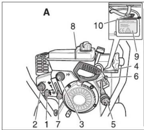

4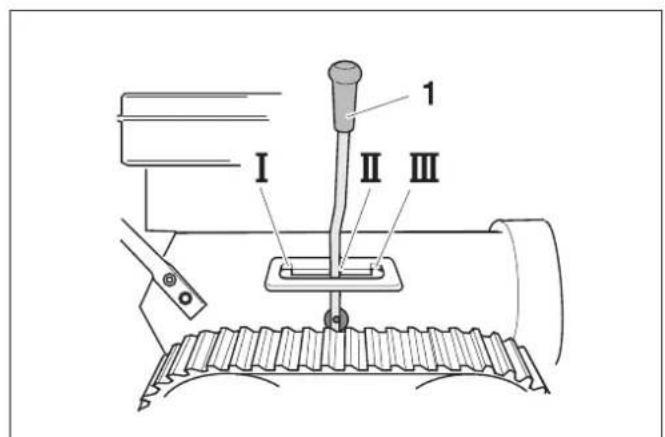
6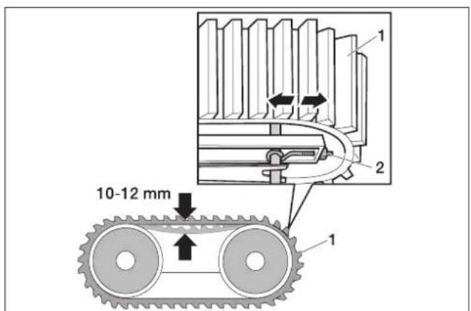
5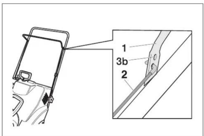
7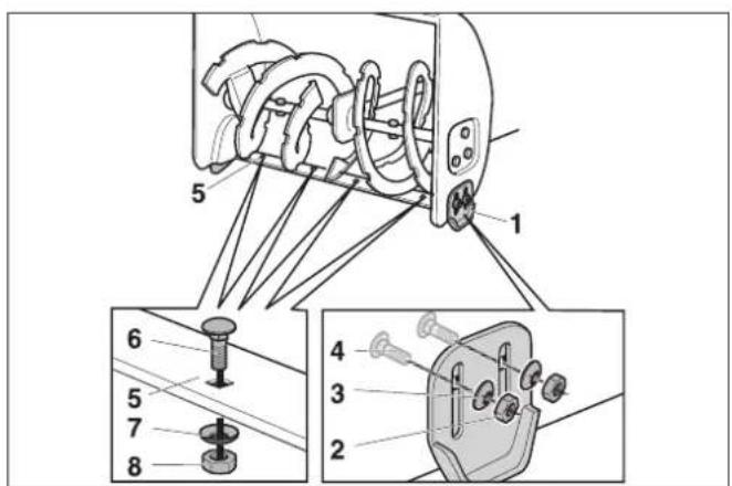
8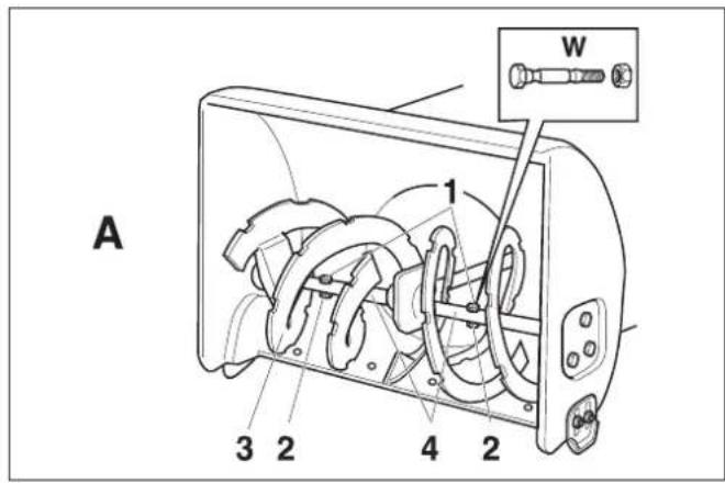
9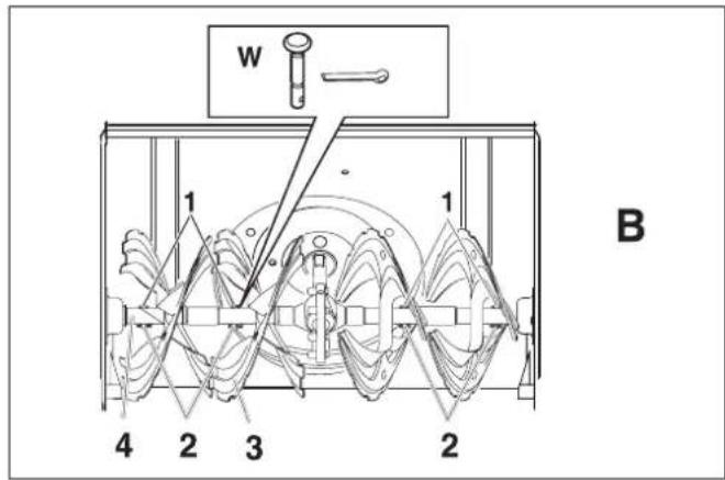
10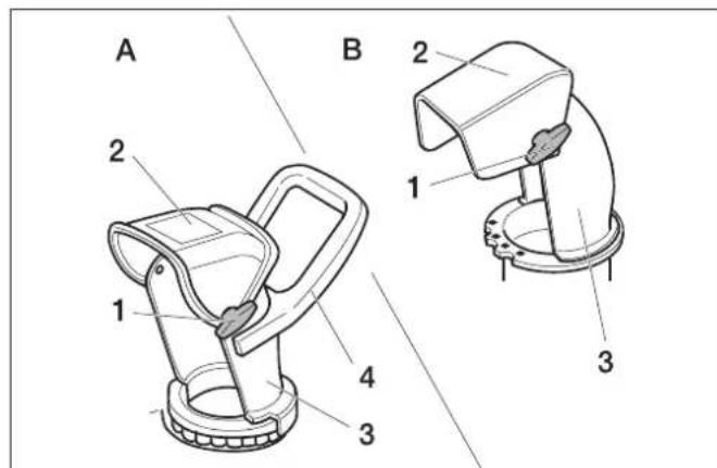
11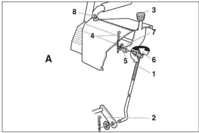
12 13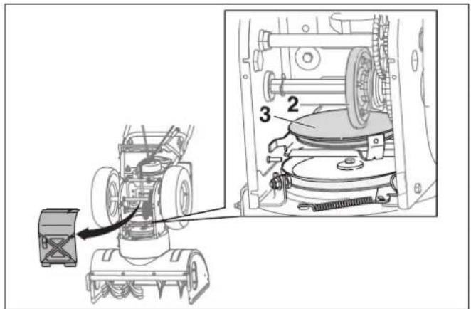

STH 8.66 W, STH 10.66 W Crt, STH 10.71 W, STH 13.84 W)
Bild 11 A
Please read and comply with these instructions prior to the
initial operation of your appliance. Retain these operating instructions for future reference or for subsequent possessors. In case of transport damage inform vendor immediately
Contents
Environmental protection 16
Overview 16
Symbols on the machine 16
Symbols in the operating instructions 16
Safety instructions 16
Safety Devices 17
Proper use 17
Before Startup 17
Start up 17
Operation 17
Transport 19
Shutdown 19
Maintenance and care 20
Troubleshooting 21
Technical specifications 23
Warranty 23
CE declaration 23
Environmental protection
| The packaging material can be recycled. Please do not throw the packaging material into household waste; please send it for recycling. | |
| Old appliances contain valuable materials that can be recycled; these should be sent for recycling.. Batteries, oil, and similar substances must not enter the environment. Please dispose of your old appliances using appropriate collection systems. | |
| Pb | Please dispose off the normal or rechargeable batteries in an environment-friendly manner. Batteries and accumulators contain substances that must not enter the environment. Please dispose them off using appropriate collection systems. |
Please do not release engine oil, fuel oil, diesel, or petrol into the environment. Protect the ground and dispose of used oil in an environmentally clean manner.
Overview
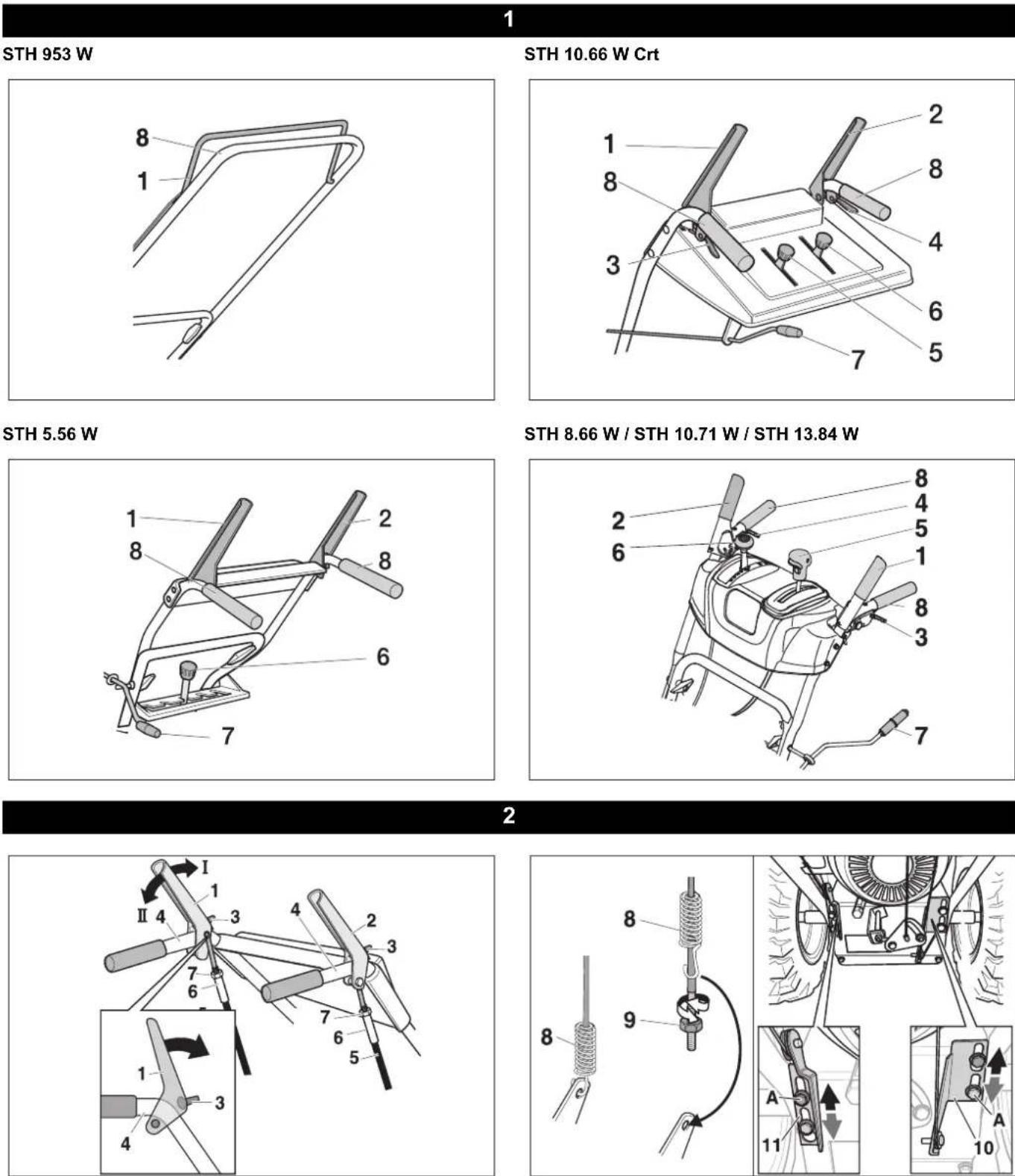
Device elements
Figure 1
1 Clutch bow/clutch lever for auger drive 2 Clutch lever for driving 3 One-way clutch lever, left 4 One-way clutch lever, right 5 Adjust the throw distance 6 Switching lever
Forward: Gears 1-5 (only STH 5.56), gears 1-6 Reverse: R1 slow/R2 fast
7 Adjust throw direction 8 Spar handle
Figure 3
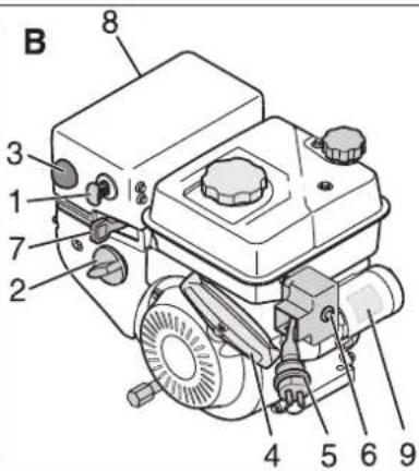
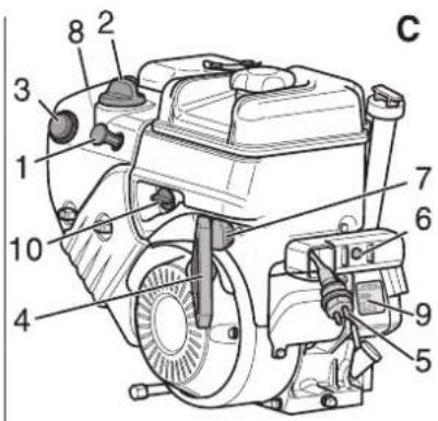
1 Ignition key 2 Choke 3 Cold start help (Tupfer) 4 Rope starter 5 Mains plug for electric starter 6 Starter knob 7 Gas lever 8 Ignition plug 9 Starter type plate 10 Fuel tap 11 Engine stop switch
Symbols on the machine
| Risk of burns! Keep safe distance from hot parts of the appliance. | |
| Wear eye and ear protection! | |
| Keep others out of the hazardous area! | |
| Risk of injury due to snow being thrown out or solid objects. | |
| Touch the parts of the appliance only when they have completely come to a standstill. | |
| Risk of injury on account of rotating parts. Keep hands and feet away from rotating parts. |
| Only clean the discharge chute with cleaning utensils.. | |
| MAX 20 PSI MAX 1,4 BAR | Risk of explosion! Never exceed the max. tyre pressure of 1.4 bar/20 PSI. |
| Switch the machine off prior to any work, such as adjustments, cleaning, testing and pull the spark plug. | |
| Gas lever position "fast" | |
| Gas lever position "slow" |
Note
Keep these symbols on the machine legible at all times.
Symbols in the operating instructions
Danger
indicates an immediate threat of danger. Failure to observe the instruction may result in death or serious injuries.
Warning
indicates a possibly dangerous situation. Failure to observe the instruction may result in light injuries or damage to property.
Note
indicates useful tips and important information.
Safety instructions
The appliance should not be operated by persons below the age of 16 years (local conditions can specify the minimum age of the operator). - Please keep children and pets away from the hazardous zones of the appliance. - Please follow the national rules and regulations while operating the machine on public streets or paths. - Do not use the appliance to transport persons. Always wear gloves, ear protectors, safety goggles, tight winter clothing and firm shoes with anti-slip soles while working.
- Never use the appliance in closed rooms; do not tank up when the engine is hot or running.
- Do not bring any parts of the body or clothes in the vicinity of rotating or hot parts of the appliance.
- Switch off engine; remove the ignition key and ignition plug if you are not working with the appliance or are leaving the machine. The same is applicable while performing setting, maintenance or repairs.
- Let the engine cool down before storing away the appliance in closed rooms.
- Store the appliance and the fuel at a safe place away from sources of fire (sparks, flame) and out of children's reach.
- Get the appliance repaired only from a specialized workshop.
Safety Devices
Safety devices serve for the protection of the user and must not be put out of operation or bypassed with respect to their function.
Clutch bow
(only STH 953 W)
When the user releases this lever, the auger drive will turn off and the machine will stop moving.
Clutch lever for snail drive
Not STH 953 W
The snail drive switches off when the user releases this clutch lever.
This lever can be stopped in a depressed state (not STH 5.56 W) if the user presses the clutch lever for travel drive and keeps it depressed. Both the levers jump back as soon as the user releases the clutch lever for the travelling drive. The auger and travel drive are switched off simultaneously.
Clutch lever for driving
Not STH 953 W
The travel drive switches off when the user releases this clutch lever.
Safety grid in the discharge shaft
The safety grid prevents intervention in the discharge shaft.
Discharge flap
Figure 9
The discharge flap (2) prevents injuries from ejected objects.
Proper use
This appliance is only to be used for clearing snow from roads and other hard surfaces according to the descriptions and safety instructions given in this Instruction Handbook.
- Any other use is in contravention of the rules!
- Using the appliance in contravention of the rules or making any high-handed
changes to the machine will absolve the manufacturer from any warranty liability.
- The user is responsible for damages to third parties and their property caused by using the appliance.
Before Startup
Unpack the appliance and assemble it
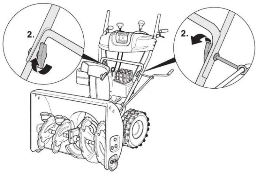
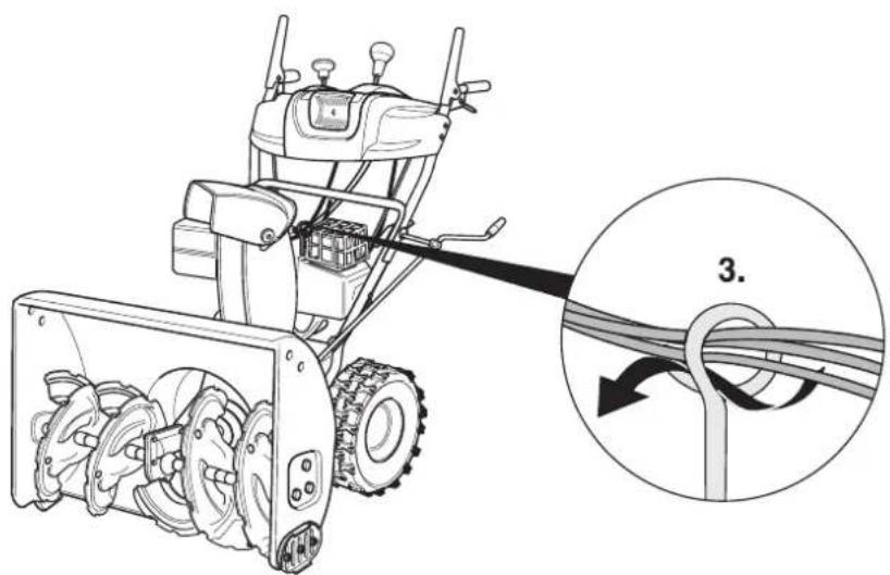
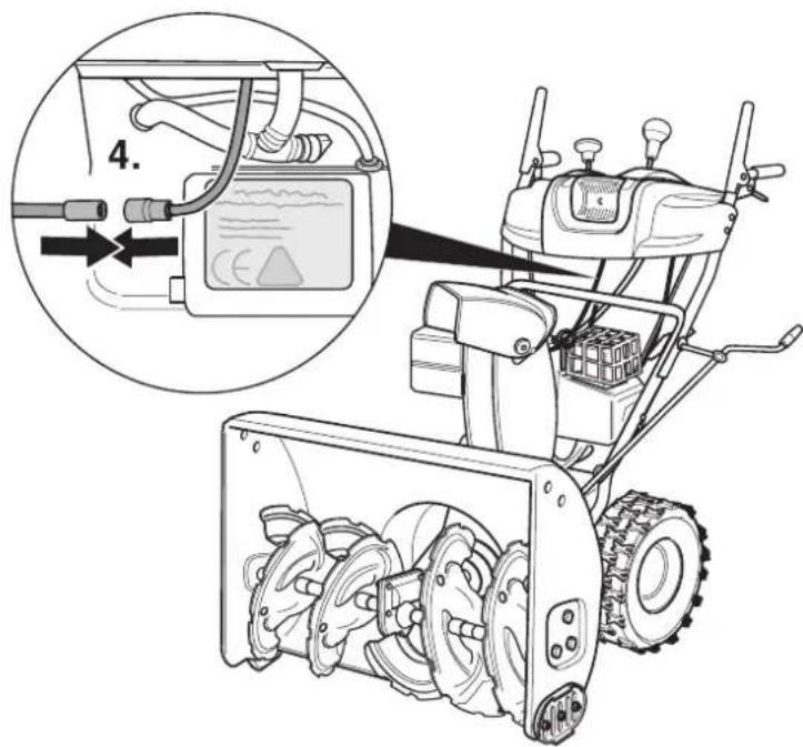
→ Check the contents of the pack before unpacking. → Assemble the appliance according to the instructions given at the end of this Instructions Handbook.
Start up
Danger
Risk of injury!
Before doing any work on the machine:
Switch off the engine. Pull out the ignition key and the spark plug. Allow the engine to cool down.
Check the machine
Perform a visual inspection before each use. Check and ensure that all safety equipment, operator control elements, and the corresponding clutch tensions/cables and screw fittings are not damaged and are tight. Replace damaged parts before operations. Not STH 953 W: Check clutches for snail and travel drive (see "Maintenance tasks"). STH 8.66 W, STH 10.66 W Crt, STH 10.71 W, STH 13.84 W: Check switching lever (see "Maintenance tasks").
Check oil level
Check oil level; refill engine oil if required (see "Engine Instruction Booklet").
Refuelling
Danger: Risk of explosion and fire! - Only use the fuels specified in the Operations Manual of the engine manufacturer. - Do not refuel the machine in enclosed spaces. Smoking and naked flames are strictly prohibited. - Ensure that no fuel reaches the hot open surfaces. - Fuel up only when the engine is switched off and is cold. - Never fill the fuel tank completely. Wipe off spilled fuel. - Store fuel only in suitable containers. Fuel up (for type of fuel see "Engine Instruction Booklet"); close the lid of the tank and wipe off fuel residues.
Check the tyre pressure
Not STH 953 W: For transportation, the tyres may show a higher level of air pressure. Check air pressure in the tyres; adjust it if required (approx. 1 bar).
Adjust the machine to suit the snow and ground conditions
Setting the working position
(machines with track drive) Figure 4
Choose a suitable position using the adjustment lever (1). - Position I: For heavy and icy snow. Auger is pressed to the ground. - Position II: For normal snow conditions. - Position III: To clear uneven paths or to transport the machine. The auger has a greater distance to the ground.
Adjusting the clearing plate (only STH 953 W)
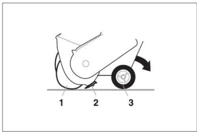
Figure 10
If the machine is sitting on even ground, the auger (1), clearing plate (2), and wheels (3) must touch the ground simultaneously.
A clearing plate that is adjusted too high will cause the snow to be thrown to the rear. A clearing plate that is positioned too low will wear faster. Tilt the appliance rearward. Loosen nuts (5). Adjust the clearing plate higher or lower (as required) and reattach. Tilt the machine backwards, check adjustment, and repeat if necessary.
Adjusting the skids
Not STH 953 W
Figure 7
The landing skids (1) can be used to adjust the distance between the ground and the clearing plate (5) in such a way that no parts of the ground (such as soil or stones) are picked up.
Machines with track drive: Set the gear lever to position II. Loosen the nuts (2) on both sides of the appliance. Adjust the landing skids according to the underground surface: set them lower for uneven or loose paths; higher for even roads and paths. Fasten the landing skids with nuts (2) in such a way that they uniformly touch the ground from the bottom.
Operation
Safety instructions
Danger
Risk of injury!
- Keep persons, especially children, and pets away from the hazardous zones.
- Operate the machine only in a safe and perfect working condition.
- Check the area where the machine is to be used and remove all objects that can get picked up and thrown out by the machine.
- Work only with adequate lighting.
- Only use the machine in walking speed.
- Work slowly and safely especially on uneven or loose paths and while reversing.
- Adjust the distance between the snail casing and the underground floor in such a way that the appliance does not pick up any foreign bodies (such as stones).
Danger
Risk of suffocation on account of carbon monoxide! Only operate the combustion engine while out in the open.
Note
Follow the national/ local regulations for the usage times (ask the local authorities, if required).
Danger
Long hours of using the appliance can cause circulation problems in the hands on account of vibrations.
It is not possible to specify a generally valid operation time, since this depends on several factors:
- Proneness to blood circulation deficiencies (cold, numb fingers). Low ambient temperature. Wear warm gloves to protect hands. -A firm grip impedes blood circulation.
- Continuous operation is worse than an operation interrupted by pauses.
In case of regular, long-term operation of the device and in case of repeated occurrence of the symptoms (e.g. cold, numb fingers) please consult a physician.
Tips for clearing the snow
- Clear up immediately after the snowfall; otherwise, the lower layer becomes ice and makes clearing difficult.
- If possible, clear the snow in the direction of the wind.
- Clear the snow in such a way that the clearing tracks overlap a little.
Working on slopes
△Danger
Risk of injury! Danger of tipping if gradient is too high. - Do not use the appliance on slopes with an inclination greater than 20% . Work slowly and cautiously, especially while changing the direction of travel. - Drive up and down the slope - never diagonally to the slope. - Pay attention to hurdles - do not work close to the inclination.
Setting the direction and distance of throw
Figure 9
Danger
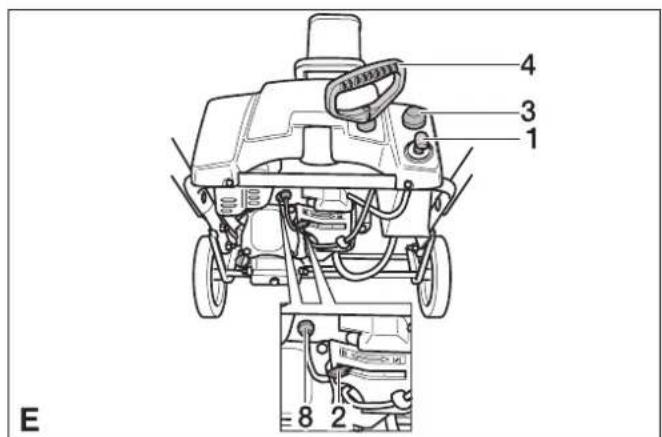
Risk of injury! Do not direct the flap (2) of the discharge shaft (3) towards persons, animals, windows, cars and doors.
Adjust throw direction
Not STH 953 W:
→ Bring the discharge shaft (3) to the desired direction by turning the crank (figure 1, item 7). Only STH 953 W: → Move the discharge chute (3) into the desired direction using the handle (4).
Note
Do not use the handle (4) to lift the machine.
Adjust the throw distance
The deeper the flap (2), the higher and farther the snow will be discharged.
Machines with lever: Press the lever (figure 1, item 5) towards the front to set the flap (2) higher and vice versa. Machines without lever: Loosen the hand knob (1) and adjust the flap (2) higher/lower as required.
Start the engine
Figure 3
Read the operating instructions of the engine manufacturer before start-up and follow the safety instructions carefully. Release the clutch bow/clutch lever for auger and travel drive before starting. Check tank contents and oil level; refill oil and fuel (see "Engine Instructions Booklet").
Note
Some models do not have a gas lever; the speed is adjusted automatically. The engine always runs with optimized speed.
Starting using rope starter
Set the fuel tank tap, if there is one, to "ON/OPEN". Insert the ignition plug into the spark plug. Not STH 953 W: Turn gas lever, if there is one, to "fast". On machines without gas levers, set the engine stop switch to "ON". Set the choke for cold start to "ON/CHOKE". Insert the ignition key into the ignition lock. Press cold start help (Tupfer) once; press it twice to seven times during cold weather (depending on the engine type). Pull the rope starter slowly till you feel the resistance and then give it a quick and hard tug. Do not allow the rope starter to recoil immediately - just let it go back slowly.
Reset the choke back to "RUN/OFF" in a step-by-step manner, if the engine is running.
Starting using electrical starter (optional)
Not STH 953 W
Danger
Risk of electric shock.
- Do not use the electric starter in the rain.
- Check whether the mains are secured with a leakage current protection switch. If not, get an electrician to install a suitable switch.
To connect the electrical starter to the mains, use only extension cables (not part of standard delivery) that have been approved for use in the open and have a safety conductor.
For example: for a max. length of 50 m
-H07RN-F 3x1.5 mm² up to -25 °C -H07BQ-F 3x1.5 mm² up to -40 °C
Danger
Risk of electric shock.
- Prior to each engine start, check the extension cables and the cables/connectors on the engine for damage.
- Please arrange immediately for the exchange of damaged parts by a skilled electrician.
- Never start the machine with damaged parts.
Warning
Improper connection of the electrical starter can cause damage to the machine or to property in its vicinity. Check whether the mains are being operated according to instructions on the type plate of the starter and is protected with appropriate fuses.
Set the fuel tank tap, if there is one, to "ON/OPEN". Insert the ignition plug into the spark plug. Turn gas lever, if there is one, to "fast". On machines without gas levers, set the engine stop switch to "ON". Insert the ignition key into the ignition lock, do not turn it. First connect the extension cable to the mains and then connect it to the mains socket. Set the choke for cold start to "ON/CHOKE". Press cold start help (Tupfer) once; press it twice to seven times during cold weather (depending on the engine type). Press the starter button (max. 5 seconds) till the engine starts. Wait for at least 30 seconds before making a fresh start. Reset the choke back to "RUN/OFF" in a step-by-step manner, if the engine is running. First disconnect the extension cable from the mains and then from the electrical starter.
Putting/changing gears
Not STH 953 W
Figure 1
Warning
Release the clutch lever for snail and travel drive before putting or changing a gear. Select the gear using the switch lever:
Forward: "1" (slow) to "5/6" (fast). Reverse: R1 slow / R2 fast.
Working with the appliance
Figure 1
Warning
Risk of damage!
- If the machine comes in contact with foreign objects (e.g. stones) or if there are unusual vibrations, switch off the machine and check the damage. Rectify the damage before starting to work again with the appliance.
- Let the engine warm up prior to using the machine. Only STH 953 W: Set the direction and distance of throw. Start the motor. Press the clutch bow and hold it. The auger is driven. The machine will move forward when the auger touches the ground. Increasing the travel speed: Raise the spar handle slightly. The auger will have better ground traction and will drive the machine forward faster. If repeated frequently, this will cause a more rapid wear of the rubber lip on the auger. Decreasing the travel speed: Press the spar handle downward. Not STH 953 W: Set the direction and distance of throw. Start the motor. Select the forward gear after releasing the clutch levers for snail and travel drives. Press the clutch lever for snail drive and keep it depressed. The snail and the throwing turbine will start up. Press the clutch lever for travel drive and keep it depressed. The appliance will move and clear the snow. The clutch lever for auger drive remains locked till this lever remains depressed (not STH 5.56 W) and can now be released. To change the gears, first release the clutch lever for travel drive and then use the switching lever for changing the gears. Machines with freewheeling levers: The machine can be lowered more easily using the freewheeling levers. To the right: Pull on the right freewheeling lever. To the left: Pull on the left freewheeling lever.
Stopping the engine
Figure 3
To avoid damage to the appliance and prevent starting problems due to humidity, let the engine run for a few minutes before switching it off (so that it gets dried). Not STH 953 W: Turn gas lever, if there is one, to "slow". On machines without gas levers, set the engine stop switch to "OFF".
Pull out ignition key.
Turn fuel tap, if there is one, to "OFF/CLOSE".
Remove the blockages from the snail or the discharge shaft.
Danger
Risk of injury!
Before doing any work on the machine:
- Switch off engine.
- Wait till all the moving parts have come to a stand-still.
- Pull out the ignition key and the ignition plug.
Figure 13
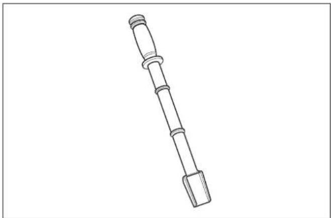
Remove the blockages using a plastic plunger or a shovel.
Snow chains (optional)
Snow chains can be purchased and used if the weather conditions are extreme.
Transport
Drive the machine
For maneuvering/travelling short distances.
Start the appliance. → Select a forward or reverse gear. Press the clutch lever for travel drive and keep it depressed. → Drive the machine carefully.
Transport without self-drive
▲ Danger
Risk of injury!
Before doing any work on the machine:
Switch off engine. → Pull out the ignition key and the ignition plug. → Allow engine to cool down. → Empty fuel tank. Transport the machine on or in a vehicle in the horizontal position. → Secure the machine against slippage or from rolling off.
Shutdown
Danger
Risk of explosion!
Smoking and naked flames are strictly prohibited. - Ensure that no fuel reaches the hot open surfaces.
Please follow these instructions if the machine is not to be used for more than one month:
Prepare the engine (see "Engine Instruction Booklet"). Empty fuel tank. Clean the device. Wipe all metallic parts with an oily cloth to protect them against rusting or spray some oil on them. Store the machine in a clean and dry room.
Maintenance and care
Maintenance schedule
Once in the season:
- Get the machine checked and serviced in an authorised workshop.
Every time before use:
- Check oil level; refill engine oil if required (see "Engine Instruction Booklet").
- Check whether all screw joints are tight; tighten them, if necessary.
- Check safety equipment.
- For machines without electric starter: Check the cables and connectors on the engine.
| Maintenance tasks After using | for | 25 h 50 h | after the | season | depending on requirements |
| Clean the discharge shaft, snail and snail casing. x | |||||
| Oil change 3) | x 4) | ||||
| Lubricate all moving and rotating parts x x | |||||
| Clean the spark plugs 1) | x | ||||
| Get the spark plugs replaced 2) | x | ||||
| Check air pressure in the tyres; increase it, if required x x | |||||
| Clean the exhaust and the air cooling system 1) | x | x | |||
| Check clutch setting; readjust, if required x | |||||
| Get the carburetor settings checked 2) | x | ||||
| Check clearing plate; replace worn out clearing plate x | |||||
| Check landing skids; replace worn out landing skids in pairs x | |||||
| Check track, adjust if necessary, replace defective track if required | x | ||||
| Replace tank lock x | |||||
| Get the exhaust checked 2) | x |
See "Engine Instruction Booklet" 2) Get these jobs done only from an authorised workshop 3) First oil change after 5 operating hours (h) 4) Change oil every 25 operating hours (h) if the machine is operated under heavy load or if the ambient temperature is high
Maintenance Works
Danger
Risk of injury! Before doing any work on the machine: - Switch off engine. - Pull out the ignition key and the ignition plug. - Allow engine to cool down.
Accessories and Spare Parts
Only use accessories and spare parts which have been approved by the manufacturer. The exclusive use of original accessories and original spare parts ensures that the appliance can be operated safely and trouble-free.
Cleaning the device
Park the machine on solid, even and horizontal ground. Remove dirt that is stuck. Clean the machine by letting in flowing water through the discharge shaft and let it dry. Clean the engine using cloth and brush.
Lubricate the machine
Lubricate all rotating and moving parts with some light oil.
Adjust the air pressure in the tyres (Not STH 953 W)
Danger
Risk of explosion! Never exceed the max. tyre pressure of 1.4 bar/20 PSI.
Recommended air pressure is approx. 1 bar
Maintenance jobs for the engine
See "Engine Instruction Booklet".
Adjust the clutch for the snail drive (Not STH 953 W)
Figure 2
Check clutch status:
Press the left clutch lever (1) forward (direction I); at the same time press the rubber (3) downward. The clutch tension (5) must be reduced. Otherwise loosen it (see "Changing the setting of the clutch tension"). Release clutch lever (1). Clutch tension (5) must be without tolerance but should also not be too tight. Else change the setting (see "Changing the clutch tension"). It should be possible to press down the clutch lever (1) completely. Otherwise, the clutch tension is too high and must be reduced (see "Changing the clutch tension").
Additional checks (see "Working with the appliance"):
Turn the auger drive on for 10 seconds with the engine running. Release the clutch lever, the auger must stop rotating.
Adjust the clutch for the travel drive (Not STH 953 W)
Figure 1
Machines with track drive: Set the gear lever to position III. Set the switching lever to the fastest forward gear (highest number). Push the machine forward after releasing the clutch lever for travel drive. While pushing, set the switching lever to the fastest reverse gear and then to the fastest forward gear. If you feel any resistance during pushing or changing the gears, reduce the clutch tension (see "Changing the clutch tension setting"). While pushing the machine, keep the clutch lever of the travel drive depressed. The wheels/tracks must be locked. Otherwise tighten the clutch tension (see "Changing the setting of the clutch tension"). If the setting is still not complete or is doubtful, see "Check travel drive".
Changing the clutch tension setting (Not STH 953 W) Figure 2
For clutch tensions with adjustable covers (6): Tightening: Loosen nuts (7) and screw in the adjustable covers (6). Loosening: Loosen adjusting covers (6) and screw in the nuts (7) in the opposite direction. For clutch tensions with release spring (8): Before doing the setting, remove the spring and then reinsert it. The clutch tension is correct when the spring expands 2-3 cm while coupling. Tightening: Screw the safety nut (9) upward. Loosening: Screw the safety nut (9) downward. For clutch cables with adjustment plates for travel drive (10) or for auger drive (11): Tightening: Loosen screw (A) depending on the adjustment plate, slide adjustment plate down and reattach the screw (A). Loosening: Loosen screw (A) depending on the adjustment plate, slide adjustment plate up and reattach the screw (A).
Checking the travel drive (Not STH 953 W)
Figure 12
Warning
Risk of damage to the machine! While tilting the machine, ensure that it retains its balance and no fuel or oil in the air filter leaks into the engine compartment or to the outside.
Loosen the screws of the frame; tilt the device forward, if required. Release the clutch lever for travel drive and shift to all gears; while doing so, the friction wheel (2) should not touch the drive disc (3). Otherwise loosen coupling tension (see "Changing the clutch tension setting"). Press the clutch lever for travel drive in each gear; the friction wheel must always touch the drive disc. Otherwise tighten the clutch tension (see "Changing the clutch tension setting"). Clean the drive disc and rubber on the friction wheel, if required; they should be grease-free. Remove ice pieces, if any.
Tensioning the V-belt of the auger (only STH 953 W)
Figure 5
If the auger runs unevenly while the engine speed remains constant, the V-belt (5) must be retensioned. If there is an additional boring (3b) on the clutch lever (1), hook the clutch cable (2) into the upper boring (3b).
If there is no additional (upper) boring or if it is already being used, visit an authorized workshop.
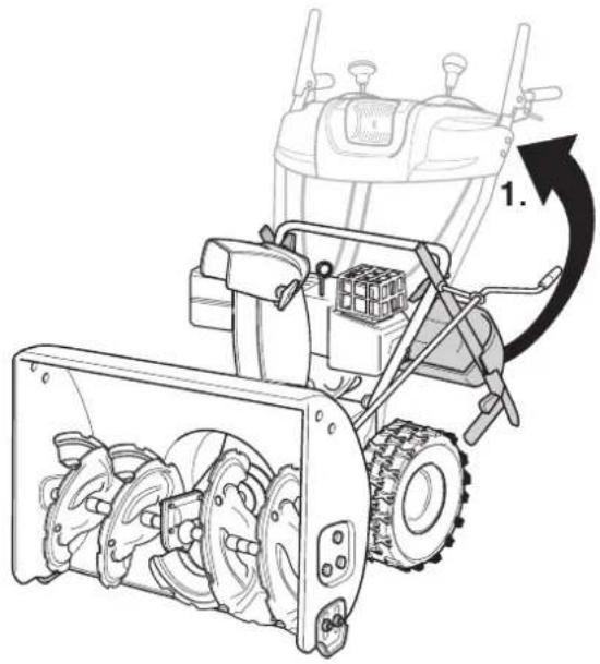
Setting the switching lever (STH 8.66 W, STH 10.66 W Crt, STH 10.71 W, STH 13.84 W)
Figure 11 A
(Machines with switching rod)
Remove spring pin (4) and underlying disc (5), remove the spindle nut (6) from the hole (7). Press the switch arm (2) downward; set the switching lever (3) to gear "6". Turn the spindle nut (6) in such a way that the pin can be inserted in the same whole (7). Secure the spindle nut with an underlying disc and spring pin.
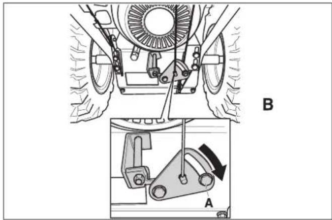
Figure 11 B
(Machines with switching tension) Set the switching lever (3) to the fastest forward gear. Loosen screw (A) and press the holder downward till the switching tension is tight. Now tighten screw (A) again. Check correct setting.
Note
This setting is required only if the fastest gear (forward or reverse) cannot be put.
Adjusting the track belt (machines with track drive)
Figure 6
The track belt (1) is adjusted correctly if it can be deflected 10-12 mm by hand. Otherwise, it has to be readjusted.
Position the machine on an even and horizontal surface so that the tracks no longer touch the ground. Turn the nut (2) until the track belt has the correct tension. Clockwise: Tighten. Anticlockwise: Loosen.
Replacing the track belt (machines with track drive)
Figure 6
Position the machine on an even and horizontal surface so that the tracks no longer touch the ground. Turn the nut (2) anticlockwise until the track belt can be removed. Replacing the track belt: Retension the new track belt using the nut (2) (see "Adjusting the track belt").
Replacing shearing bolts
Not STH 953 W
Figure 8
The auger (3) is fastened to the drive shaft (4) using shearing bolts (1) and locknuts or splints (2). The bolts are designed in such a way that they break (shear off) when the snail comes in contact with foreign bodies. This protects the machine against damages. These parts should only be replaced by original spare parts (Spare bolts and lock nuts or splints are included as options in standard delivery, part W).
Remove broken bolts (1) and locknut or splint (2); clean and lubricate the fastening point. Use new shearing bolt and new locknut or splint.
Replacing the clearing plate
Only STH 953 W:
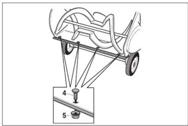
Figure 10
Tilt the appliance rearward. Remove screws (4) and nuts (5). Replace the clearing plate (2). Fasten new clearing plate to the casing using screws and nuts. Tilt the machine backwards, check (see "Adjusting the clearing plate").
Not STH 953 W:
Figure 7
Remove screws (6), underlying discs (7) and nuts (8). Replace the clearing plate (5). Fasten new clearing plate to the casing using screws, underlying disc and nuts.
Replacing the landing skids (Not STH 953 W)
Figure 7
Remove nuts (2), underlying discs (3) and screws (4). Loosen the landing skids (1) on both the sides of the casing. Adjust the new landing skids (see "Adjusting the landing skids").
Troubleshooting
Danger
Risk of injury! Before doing any work on the machine: - Switch off engine. - Pull out the ignition key and the ignition plug. - Allow engine to cool down.
Note
Some of the functioning problems have simple causes and you can rectify them easily. Call up an authorised workshop in case of doubt or if mentioned explicitly.
Note
Repairs should only be done by authorised workshops using original spare parts.
Troubleshooting
| Fault Possible cause | Remedy of whom | ||
| Engine does not start | Fuel tank empty. Refill the fuel tank. Operator | ||
| Fuel idling for a long time. Remove the old fuel in a | suitable container in the open (See "Engine Instruction Booklet"). Fill up the tank with clean, fresh fuel. | Operator | |
| Engine in cold state; choke not set to "ON/CHoke". | Set the choke to "ON/CHoke". Operator | ||
| Gas lever no set to "fast" (not STH 953 W). | Set the gas lever to "fast". | Operator | |
| Engine stop switch not set to "ON" (machines without gas levers). | Set the engine stop switch to "ON". Operator | ||
| Ignition plug not inserted. Insert the ignition plug into the spark plug. Operator | |||
| Spark plug is dirty. Clean the spark plug (see "Engine Instruction Booklet"). | Customer | Operator | |
| Spark plug is defective. Replace the spark plug. | and ventilation hole. Operator | ||
| Carburetor is overflowing. | Adjust the carburetor. | Customer Service | |
| Engine is running erratically | Choke set to "ON/CHoke". | Choke set to "RUN/OFF". | Operator |
| Ignition plug is loosely inserted. | Fix the spark-plug connector properly. | Operator | |
| Fuel idling for a long time. Water or dirt in the fuel system. | Remove the old fuel in a suitable container in the open (See "Engine Instruction Booklet"). Fill up the tank with clean, fresh fuel. | Operator | |
| Ventilation hole in tank lid blocked. Clean tank lid | and Vibration hole. | Customer Service | |
| Carburetor out of alignment. | Adjust the carburetor. | Customer Service | |
| Machine does not clear snow | Shearing bolts torn off. | Replace shearing bolts (see "Replacing shear-ing bolts"). | Operator |
| Snail or discharge shaft is blocked. | Stop the engine, pull out the ignition plug. Remove the blockage. | Operator | |
| Clutch tension for snail drive is not set properly. | Set clutch tension (see "Setting clutch for snail drive"). | Operator | |
| V-belt loose. | STH 953 W: Tension the V-belt (see "Tensioning the V-belt of the auger"). | Operator | |
| Not STH 953 W: Tighten V-Belt. | Customer Service | ||
| V-belt torn. | Replace V-belt. | Customer Service | |
| Machinen does not run (not STH 953 W) | Clutch tension for travel drive is not set properly. | Adjust clutch tension (see "Setting the clutch for travel drive"). | Operator |
| V-Belt is loose or torn. | Tighten the loose V-Belt. Replace torn V-Belt. | Customer Service | |
| Travel drive is coated with ice. | Remove the ice (see "Check travel drive"). | Operator | |
| Friction wheel rubber is torn. | Replace friction wheel rubber. | Customer Service | |
| Excessive vibration | Loose parts or damaged snail. | Stop the engine immediately, pull out the ignition plug. Tighten loose screws and nuts. Repair damaged snail. | Customer Service |
| Gears can be switched with great difficulty (not STH 953 W) | Clutch tension for travel drive is not set properly. | Adjust clutch tension (see "Setting the clutch for travel drive"). | Operator |
| Gear lever not adjusted correctly (not STH 5.56 W). | Check switching lever (see "Setting the switching lever"). | Operator | |
| Travel drive is coated with ice. | Remove the ice (see "Check travel drive"). | Operator |
Information about engine
The engine manufacturer assumes liability for all engine-related problems as regards output, output measurement, technical data, warranty and servicing. For further details, please refer the separate holder/ operator manual of the engine manufacturer.
Technical specifications
| STH 953 W | STH 5.56 W | STH 8.66 W | STH 10.66 W | Crt | STH 10.71 W | STH 13.84 W | ||
| Part no.: | -- | 1.332-101 | 1.335-101 | 1.335-201 | 1.335-302 | 1.335-203 | 1.335-204 | |
| Type -- Snow clearer | with wheels | Snow clearer with wheels | Snow clearer with wheels | Snow clearer with track belt | Snow clearer with wheels | Snow clearer with wheels | ||
| Motor -- MTD, 4- | stroke | MTD, 4- stroke | B&S, 4- stroke | B&S, 4- stroke | B&S, 4- stroke | B&S, 4- stroke | ||
| Rated power | kW/HP | 2,0/2,7 | 3,5/4,8 | 6,0/8,2 | 7,5/10,2 | 7,5/10,2 | 9,7/13,2 | |
| Cylinder capacity | cm3 | 123 | 179 | 250 | 305 | 305 | 342 | |
| Operating speed | 1/min | 3600 | 3600 | 3550 | 3600 | 3550 | 3400 | |
| Capacity of fuel tank, normal petrol (unleaded) | I | 1,9 | 1,9 | 3,8 | 3,8 | 3,8 | 7,6 | |
| Working width | mm | 530 | 560 | 660 | 660 | 710 | 840 | |
| Working speed | km/h | Step speed | Step speed | Step speed | Step speed | Step speed | Step speed | |
| Surface area, max. | m2/h | 1700 | 1700 | 2000 | 2000 | 2200 | 2500 | |
| Length | mm | 768 | 1111 | 1213 | 1257 | 1213 | 1492 | |
| Width | mm | 578 | 629 | 730 | 749 | 781 | 959 | |
| Height | mm | 645 | 800 | 800 | 851 | 800 | 864 | |
| Weight | kg | 36 | 80 | 100 | 98 | 102 | 135 | |
| Amount of oil | I | approx. 0.6 | approx. 0.6 | approx. 0.83 | approx. 0.83 | approx. 0.83 | approx. 0.83 | |
| Oil types above 0 °C | -- | SAE 30 | SAE 30 | SAE 30 | SAE 30 | SAE 30 | SAE 30 | |
| Oil types below 0 °C | -- | SAE 5W30 | SAE 5W30 | SAE 5W30 | SAE 5W30 | SAE 5W30 | SAE 5W30 | |
| Oil types below -18 °C | -- | SAE 0W30 | SAE 0W30 | SAE 0W30 | SAE 0W30 | SAE 0W30 | SAE 0W30 | |
| Noise emission | ||||||||
| Sound pressure level (EN 60704-1) | dB(A) | 92 | 92 | 98 | 98 | 94 | 98 | |
| Guaranteed sound power level (2000/14/EC) | dB(A) | 104 | 104 | 110 | 110 | 106 | 110 | |
| Machine vibrations | ||||||||
| Vibration total value (ISO 5349) | ||||||||
| Upper limbs | m/s2 | 5 | 5 | 5 | 5 | 5 | 5 | |
Warranty
The warranty terms published by our competent sales company are applicable in each country. We will repair potential failures of your appliance within the warranty period free of charge, provided that such failure is caused by faulty material or defects in fabrication. In the event of a warranty claim please contact your dealer or the nearest authorized Customer Service center. Please submit the proof of purchase.
CE declaration
We hereby declare that the machine described below complies with the relevant basic safety and health requirements of the EU Directives, both in its basic design and construction as well as in the version put into circulation by us. This declaration shall cease to be valid if the machine is modified without our prior approval.
Product: Snow clearer
Type: 1.332-xxx, 1.335-xxx
Relevant EU Directives
98/37/EC
89/336/EEC (+91/263/EEC, 92/31/EEC,
93/68/EEC)
2000/14/EC
Applied harmonized standards
EN ISO 12100-1
EN ISO 12100-2
EN ISO 14982
ISO 8437
Applied conformity evaluation method
Appendix V
Sound power level dB(A)
STH 953 W
Measured: 102
Guaranteed: 104
STH 5.56 W
Measured: 102
Guaranteed: 104
STH 8.66 W
Measured: 108
Guaranteed: 110
STH 10.66 W Crt
Measured: 108
Guaranteed: 110
STH 10.71 W
Measured: 104
Guaranteed: 106
STH 13.84 W
Measured: 108
Guaranteed: 110
5.957-646
The undersigned act on behalf and under the power of attorney of the company management.

Type: 1332-xxx, 1335-xxx
89/336/CEE (+91/263/CEE, 92/31/CEE, 93/68/CEE)
2000/14/CE
(STH 8.66 W, STH 10.66 W Crt, STH
10.71 W, STH 13.84 W)
Fig. 11 A
(Machine with gear lever)
Type: 1.332-xxx, 1.335-xxx
Applicable EC Directives
98/37/EC
89/336/EEC (+91/263/EEC, 92/31/EEC,
93/68/EEC)
2000/14/EC
Adjusting the base plate
(Only STH 953 W)
Figure 10
When the machine is on a level surface, the worm (1), base plate (2) and wheels (3) should all touch the ground at the same time.
Adjust the skid shoes.
(Not STH 953 W)
Figure 7
Still in coupling for driving
(Not STH 953 W)
Figure 1
For machines with tracks: Set the adjustment handle to position III. Set the gear lever to the fastest forward (highest digit). Push the machine forward with the coupling lever for driving released.
STH 8.66 W, STH 10.66 W Crt, STH 10.71 W, STH 13.84 W)
Fig. 11 A
Type: 1332-xxx, 1335-xxx
89/336/EEC (+91/263/EEC, 92/31/EEC,
93/68/EEC)
2000/14/EC
Applied harmonized standards
EN ISO 12100-1
EN ISO 12100-2
EN ISO 14982
ISO 8437
Applied method for conformity assessment
Annex V
| Lydeffektnivà dB(A) | |
| STH 953 W | |
| Målt: | 102 |
| Garanteret: | 104 |
| STH 5.56 W | |
| Målt: | 102 |
| Garanteret: | 104 |
| STH 8.66 W | |
| Målt: | 108 |
| Garanteret: | 110 |
| STH 10.66 W | |
| Crt | |
| Målt: | 108 |
| Garanteret: | 110 |
| STH 10,71 W | |
| Målt: | 104 |
| Garanteret: | 106 |
| STH 13,84 W | |
| Malt: | 108 |
| Garanteret: | 110 |
5.957-646
(STH 8.66 W, STH 10.66 W Crt, STH 10.71
W, STH 13.84 W)
Figure 11 A
(Unit with coupling rod)
Forward: 1" (slow) -5/6" (fast) Reverse: R1-slow/R2-fast
(STH 8.66 W, STH 10.66 W Crt, STH 10.71 W, STH 13.84 W)
Figure 11 A



Safety devices
Safety devices serve to protect the user and must not be put out of operation while working in automatic mode.
Clutch lever
(Only for STIHL 953 W)
When the operator releases this lever, the clutch of the drive disengages and the machine stops.
Clutch lever for the brush cutter drive
(Not for STIHL 953 W)
The brush cutter drive disengages when the user releases this lever.
This lever can be locked in the pressed position (except for STIHL 5.56 W) when the user presses and holds the clutch lever of the drive. As soon as the user releases the clutch lever of the drive, both levers spring back. The drive and brush cutter drives disengage simultaneously.
Clutch lever for the drive
(Not for STIHL 953 W)
The drive disengages when the user releases this lever.
Protective grid in the ejection chute
The protective grid prevents penetration into the ejection chute.
Ejector flap
KlananBbIpaCbIbATEJ(2)n3aunTbOT TpaBM,NOlyuayemBX BCJeCDTBNEBbIpaCbIBAHN ppeDMTOB.
Intended use
This device is intended exclusively as a snow blower for removing snow from roads and light surfaces according to the descriptions and safety rules given in this operating manual.
Any other use is considered improper! - Use of the device not for its intended purpose, unauthorized modifications of the device exclude the manufacturer's liability. - The user is responsible for damages that occur to third parties or their property as a result of using the device.
Work area
Unpacking and assembling the device
→ When unpacking, check the contents of the packaging. Assemble the device as shown in the appendix of this manual.
Starting work
Safety
Danger of injury! Before all work with the device:
Switch off the engine. Remove the ignition key. Remove the spark plug cap. Let the engine cool down.
Checking the device
→ Perform a visual inspection before starting work. → Check for damage and tightness of the protective devices, control elements and the cables/cables attached to them, as well as all screw connections. → Before work, replace all damaged parts. He STH 953 W:
Setting the discharge distance
The cover (2) is installed higher, and the further it is, the more snow will be thrown out.
Tool with handle:
Press the lever forward (Fig. 1, item 5) to set the cover (2) higher and turn it. ■Tool without handle: Release the button (1) and set the cover (2) higher or lower as needed.
Starting the engine
Fig. 3
→Before starting, read the operator's manual of the engine manufacturer and follow the safety rules. →Before starting, release the clutch lever/gear shift lever of the drive and the clutch lever of the wheel drive. →Check the fuel tank content and oil level, add oil and fuel if necessary (see "Engine Manual").
Note
On some models with throttle lever, the number of revolutions is set automatically. The engine always runs at optimal speed.
Starting with recoil starter
→Turn the fuel valve to the "OPEN" position if available. →Install the spark plug cap on the spark plug. Do not use the 953 W:
Set the throttle lever, if available, to "FAST". For tools without throttle lever, set the engine stop switch to the "ON" position.
→When the engine is cold, set the air choke to "CLOSED". Insert the key into the ignition lock. Press the primer bulb once for cold start, and for a warm engine press it one to seven times (depending on engine type). →Slowly pull the starter rope until resistance is felt, then return it quickly and firmly. Do not allow the starter rope to rewind quickly, but slowly guide it back. →When the engine starts, gradually move the air choke back to its original position, "RUN/OFF".
Starting with electric starter (optional) (Not for 953 W)
Danger
Danger of electric shock.
Use the electric starter only during operation. Check that the electrical circuit is protected by an automatic circuit breaker. Otherwise, call an electrician so that the installation complies with the automatic circuit breakers.
Connect the starter to the mains only through an extension cord (not included) that is suitable for outdoor use and has a protective earth connection.
For example, up to a maximum length of 50 m: -H07RN-F3x1.5 mm² up to 25°C -H07BQ-F3x1.5 mm² up to 40°C
Danger
Danger of electric shock.
- Before each start of the engine, check the cables and the engine housing for damage. A damaged part must be replaced immediately by a qualified electrician. Never start the device with damaged parts.
Warning
If the electric starter is connected improperly, damage may occur to the device or its surroundings. Check that the electrical installation is operated in accordance with the data on the starter's nameplate and is protected by the appropriate fuse.
→ Turn the fuel tap to the "ON" position if available. → Set the choke lever to the "CHOKE" position. → Set the throttle lever, if available, to the "FAST" position. For devices without a throttle lever,
Set the stop switch to the "ON" position. Insert the key into the ignition lock, but do not turn it. → Connect the extension cord first to the device's connector, then to the wall outlet. → On first start, set the air flap to the "ON/CHOKE" position. Press the auxiliary start aid (primer) once for a cold start, from one to seven times depending on the engine type. → Hold the starter button pressed (max. 5 seconds) until the engine starts. Wait at least 30 seconds between start attempts. → When the engine is running, gradually move the air flap back to its original position, "RUN/OFF". → Disconnect the extension cord from the mains first, then from the electric starter.
Switching on/off the transmission
(Not for model 953 W)
Fig. 1
Warning
Releasing the clutch and the cold drive engages or disengages the gear.
Attention:
Forward: 1" (slow) to 5/6" (fast). Reverse: R1-slow/R2-fast
Operating the device
Fig. 1
Pressure adjustment
Danger of damage!
When the device is subjected to impact or foreign objects (e.g., stones) or during strong vibrations, it should be switched off and checked for damage. Before continuing to work with the device, repair any detected damage. - Before starting the equipment, the engine must be checked. Only for STIHL 953 W: Setting the throw distance and direction. Start the engine. Press and hold the clutch lever. The cutting tool is engaged. Via the ground contact, the tool is set in motion. → Increase the travel speed
Press the rear handle. The tool has improved ground contact and allows faster movement. More frequent repetition leads to accelerated wear of the rubber pad of the tool.
→ Decrease the travel speed: Press the rear handle down. Only for STIHL 953 W: Setting the throw distance and direction. Start the engine. → On machines with a clutch lever, engage the clutch by moving the lever to the desired position. → Press and hold the clutch lever for the drive. The tool and turbine are engaged. Press and hold the clutch lever for the drive. The device moves and throws snow. While this lever is pressed (not for STIHL 5.56 W), the clutch lever for the drive remains locked and can be released. → To change gears, release the drive clutch lever and then shift gears with the gear lever. → Devices with a freewheel lever:
With the freewheel levers, you can control the device. Right: Pull the right freewheel lever. Left: Pull the left freewheel lever.
Stopping the engine
Fig. 3
To prevent damage to the device or problems starting due to moisture, let the engine run for a few minutes (to dry it) before storing the device. Not for STIHL 953 W:
Set the throttle lever, if available, to the slow position. For devices without a throttle lever, set the stop switch to the "OFF" position.
Pull out the ignition key. → Turn the fuel tap to the "OFF/CLOSE" position, if available.
Clearing a clogged nozzle of the ejection chute
Danger
Danger of injury! Before all work on the machine: -Switch off the engine. -Wait until all moving parts have come to a standstill.
Pull out the ignition key and remove the spark plug cap. Fig. 13 → Clear the blockage with a wooden stick or a brush.
Anti-slip chains (optional)
In extreme winter conditions, you can purchase and use anti-slip chains from specialized retailers.
Transport
Moving the machine
Maneuvering/overcoming short distances.
Start the machine. Select forward or reverse gear. Press and hold the drive lever. → Carefully move the machine.
Transport without its own drive
Danger
Danger of injury! Before all work on the machine:
Switch off the engine. Pull out the ignition key and remove the spark plug cap. → Let the engine cool down. → Empty the fuel tank. → Transport the machine on a transport vehicle, in a horizontal position. Secure the machine against slipping or tipping.
Decommissioning
- Danger and operation of the open flame. Make sure that the flame does not come into contact with hot surfaces.
If the appliance is not used for more than a month, please follow the following points:
→ Prepare the appliance (see "Engine Manual") Empty the fuel tank. Clean the appliance. → For storage, remove the spark plug and pour a small amount of oil into the cylinder. → Place the appliance in a dry and clean room.
Maintenance and technical service
- Check the oil level, if necessary top up (see "Engine Manual").
- Check the screw connections and the sealing seat, if necessary tighten.
-Check the protective devices. In devices with an electric starter mechanism: check the cable and the plug connector.
Engine hours (4) when operating with
high load or high
ambient temperature
Maintenance work
service
Danger
Speed before starting the device:
- Turn off the engine.
Remove the ignition key and then remove the spark plug cap.
Let the engine cool down.
Accessories and spare parts
Only use accessories and spare parts that have been approved by the manufacturer. Using original accessories and spare parts guarantees you reliable and trouble-free operation of the device.
Cleaning the device
Place the device on a firm, level, horizontal surface. Remove any stuck dirt. Clean the device with water and let it dry. Clean the motor with a brush and cloth.
Lubricating the device
Lubricate all
rotating and moving parts with oil.
Setting the pressure in the covers
(not for 953 W)
Danger
The maximum air pressure should not exceed 1.4 bar.
The recommended air pressure in the tires is approximately 1 bar.
Engine maintenance
See the engine manual
Clutch adjustment of the servo
drive
(not for ETH 953 W)
Fig. 2
Checking the clutch condition:
Press the clutch lever (1) forward (direction of travel), while pressing the rubber (3). The clutch play (5) should loosen slightly. Otherwise, loosen it (see "Adjusting the clutch play"). Release the clutch lever (1). The clutch play (5) should have no play, but should not be very tight. Otherwise, adjust the setting (see "Adjusting the clutch play"). →The clutch lever (1) must be pressed all the way down. Otherwise, the clutch play is too tight and must be loosened (see "Adjusting the clutch play").
Additional control (see
"Working with the device"):
→With the engine running, engage the servo drive for 10 seconds. Release the clutch lever, the reserve shaft can no longer rotate.
Clutch adjustment of the travel drive
(not for ETH 953 W)
→ With the tracked undercarriage: bring the lever to position III. → Switch the lever to a higher forward gear (higher number). Push the machine forward with the clutch lever released. While pushing, bring the lever to the fastest reverse gear and then to the fastest forward gear. → If resistance is felt when pushing or shifting, reduce the track tension (see "Adjusting track tension"). Push the machine, press the clutch lever. The wheels/tracks should lock. If not, increase the track tension (see "Adjusting track tension"). → If the adjustment is still not ideal or raises doubts, see "Checking the undercarriage".
Adjusting track tension
(not for model 953 W)
Tension mechanisms with adjusting coupling (6): → To tighten: release the locknut (7) and tighten the adjusting coupling (6) in the opposite direction. To loosen: release the adjusting coupling (6) and tighten the locknut (7) in the opposite direction. Tension mechanisms with release spring (8): → Before installing the spring, it must be released, then re-engaged. The tension mechanism is correctly installed if, when the spring is released, it extends by 2-3 cm. → To tighten: turn the counter nut (9) upward. To loosen: turn the counter nut (9) downward. Tension mechanisms with adjusting plate for the drive shaft (10) or the final drive shaft (11): → To tighten: loosen (A) depending on the adjusting plate, move downward
Set the handle (A) and tighten screw (A) again. → Loosening: Loosen screw (A) depending on the adjusting screw, lift the set handle up and tighten screw (A) again. (Not for STH 953 W) Danger of damaging the device! When tilting the device, make sure it remains balanced and that no oil or coolant leaks into the motor or switch compartment. Tighten the screws on the frame housing, otherwise the device may tip over. → When the clutch lever is released, switch to all gears; the friction wheel (2) must not touch the drive disc (3). Otherwise, loosen the clutch tension mechanism (see "Adjusting the clutch tension"). → For each gear, press the clutch lever; the friction wheel must be in contact with the drive disc. Otherwise, increase the clutch tension (see "Adjusting the clutch tension"). → If necessary, clean the drive disc and the friction wheel. In this case, free the front parts from dirt. (Only for STH 953 W) If the engine runs unevenly at low speeds, tighten the V-belt (5). → If the clutch lever (1) has an additional hole (3b), insert the clutch pin (2) into the hole located above (3b). → If the additional hole (located above) is absent or already in use, contact a specialized service. (STH 8.66 W, STH 10.66 W Crt, STH 10.71 W, STH 13.84 W) (Devices with switch knob) → Remove the spring washer (4) and the flat washer (5), pull out the feed rod (6) from the hole (7). → Press the switch lever (2) down, set the switch lever (3) to position "b".
Checking the feed drive
Fig. 12
△Warning
Tightening the V-belt of the milling disc
Fig. 5
Setting the switch lever
Fig. 11 A
→Turn the feed rod (6) so that the hole (7) can be aligned with the pin. Secure the feed rod with the flat washer and the spring washer.
Fig. 11 B
(Devices with cable pull)
→Set the switch lever (3) to the fastest forward gear. Loosen screw (A) and press the holder down until the cable is taut. Tighten screw (A) again. →Check the correct setting.
Note
This adjustment is only necessary if it is impossible to engage the highest gear (forward or reverse).
Adjust the tension belt
The tensioning screw (1) is set correctly if it can be extended by 10-12 mm. Otherwise, it must be shortened.
→ Place the device on a stable, horizontal surface so that the tracks do not touch the ground. → Turn the nut (2) until the track belt has the correct tension. In the direction of the arrow: tension. Against the direction of the arrow: loosen.
Replace the track belt
Power, power measurement
Technical data, warranty and service.
More detailed information can be
found in the separately supplied
operator's manual from the
engine manufacturer.
Technical data
Type: 1.332-xxx, 1.335-xxx
Essential directives: EC 98/37/EC, 89/336/EEC (+91/263/EEC, 92/31/EEC, 93/68/EEC), 2000/14/EC
Applied harmonized standards
EN ISO 12100-1
EN ISO 12100-2
EN ISO 14982
ISO 8437
Annex V
Sound power level dB(A) STH 953 W
STH 8.66 W, STH 10.66 W Crt, STH 10.71 W, STH 13.84 W)
Fig. 11A
(STH 8.66 W, STH 10.66 W Crt, STH 10.71 W, STH 13.84 W)
Fig. 11A
89/336/EEC (+91/263/EEC 92/31/EEC, 93/68/EEC)
2000/14/EC
Harmonized standards used
EN ISO 12100-1
EN ISO 12100-2
EN ISO 14982
ISO 8437
STH 8.66 W, STH 10.66 W Crt, STH 10.71 W, STH 13.84 W)
Figure 11 A
(machines with shift frame) -> Remove the spring pin (4) and washer (5), take the spindle nut (6) out of the bore (7).
-> Press the shift arm (2) downwards, switch the shift lever (3) to gear "6". Turn the spindle nut (6) so that the pin can be inserted into the same bore (7). Secure the spindle nut with the washer and spring pin.
Figure 11 B
(machines with shift cable)
-> Switch the shift lever (3) to the fastest forward gear. -> Loosen screw (A) and press the bracket downwards to tension the shift cable. -> Retighten screw (A). Check the correct adjustment.
Warning
Type: 1.332-xxx, 1.335-xxx
Subject of EC Directive:
98/37/EC
89/336/EEC (+91/263/EEC, 92/31/EEC, 93/68/EEC)
2000/14/EC
STH 8.66 W, STH 10.66 W Crt, STH 10.71 W, STH 13.84 W)
Fig. 11 A
89/336/EEC (+91/263/EEC, 92/31/
EEC, 93/68/EEC)
2000/14/EC
(STH 8.66 W, STH 10.66 W Crt, STH
10.71 W, STH 13.84 W)
Fig. 11 A
(machines with levers)
-> Remove the plug (4) and washer (5), and take the spindle nut (6) out of the bore (7). -> Press the lever (2) downwards and set the gear (3) to speed "6". Turn the spindle nut (6) until the extension can be inserted into the same bore (7). -> Secure the spindle nut with the washer and spring plug.
Fig. 11 B
(machines with rope) Put the gearbox (3) into the highest forward speed.
-> Loosen screw (A) and press the holder downwards until the rope is tensioned. -> Retighten screw (A). -> Check that the adjustment is correct.
Note
This adjustment is only necessary if the highest speed (forward or reverse) cannot be engaged.
Type: 1.332-xxx, 1.335-xxx
(STH 8.66 W, STH 10.66 W Crt, STH 10.71 W, STH 13.84 W)
Figure 11 A
STH 8.66 W/STH 10.71 W/STH 13.84 W




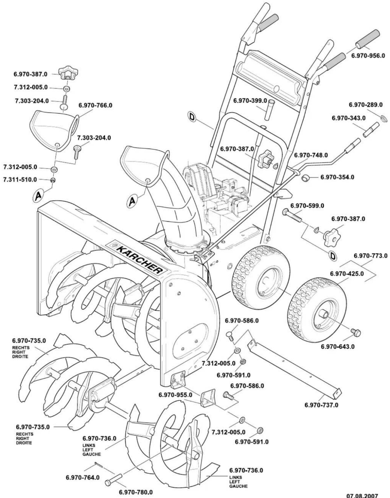
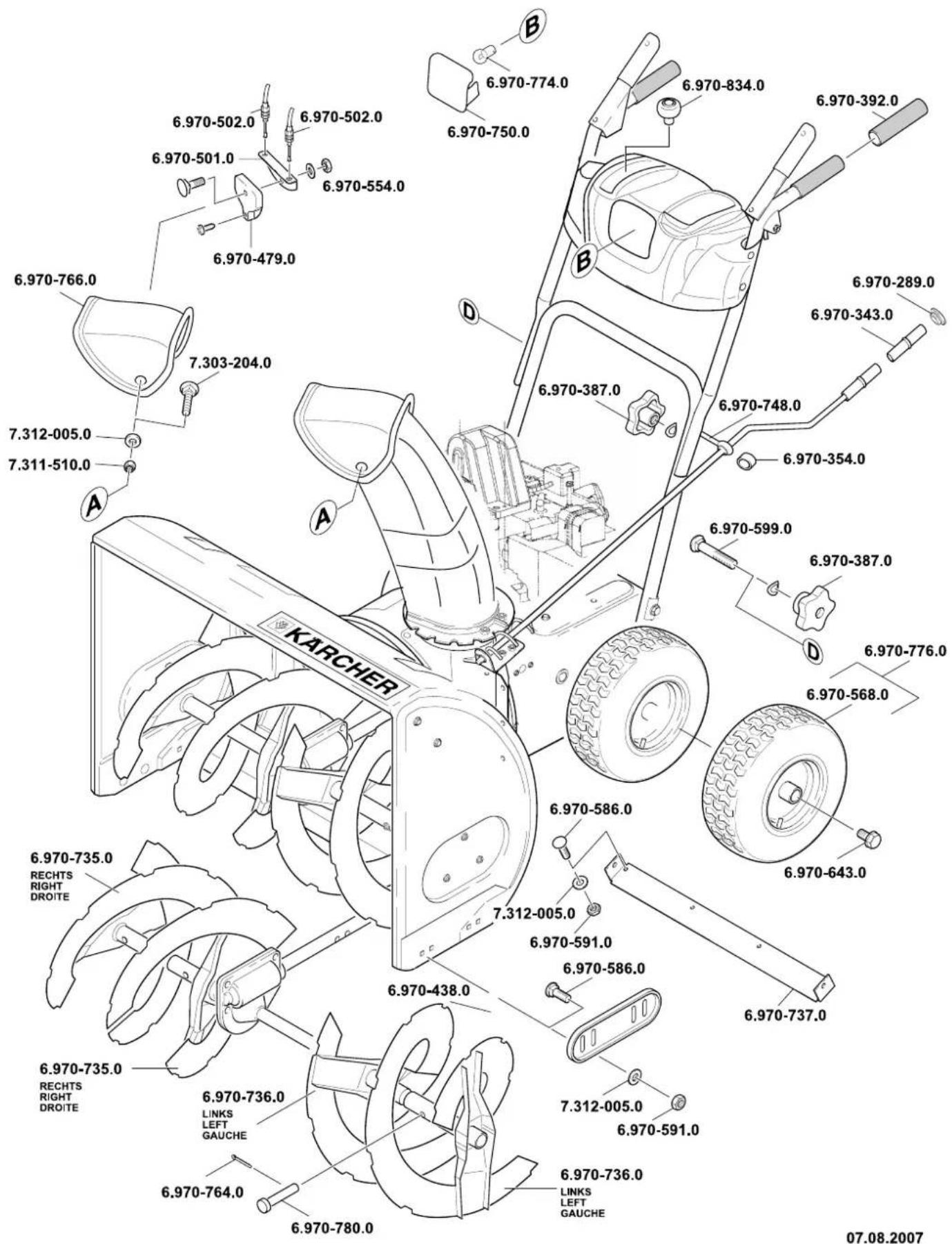
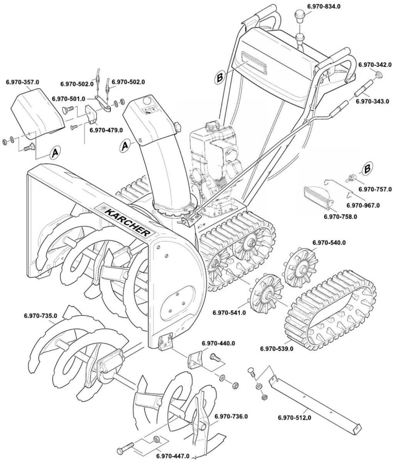
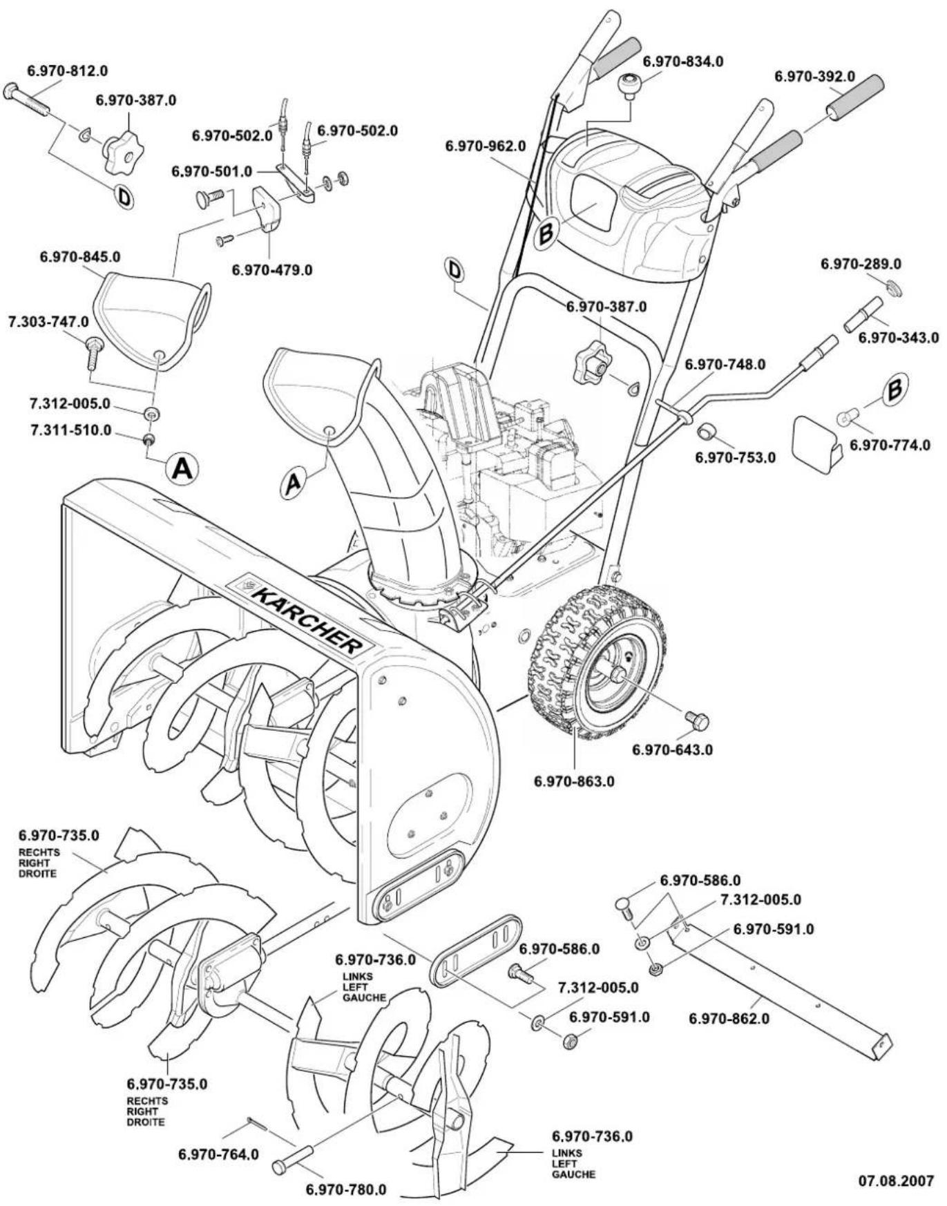
07.08.2007
- BILD 11 A
- CONTENTS
- ENVIRONMENTAL PROTECTION
- OVERVIEW
- DEVICE ELEMENTS
- FIGURE
- SYMBOLS ON THE MACHINE
- NOTE
- SYMBOLS IN THE OPERATING INSTRUCTIONS
- DANGER
- WARNING
- SAFETY INSTRUCTIONS
- SAFETY DEVICES
- CLUTCH BOW
- CLUTCH LEVER FOR SNAIL DRIVE
- CLUTCH LEVER FOR DRIVING
- SAFETY GRID IN THE DISCHARGE SHAFT
- DISCHARGE FLAP
- PROPER USE
- BEFORE STARTUP
- UNPACK THE APPLIANCE AND ASSEMBLE IT
- START UP
- CHECK THE MACHINE
- CHECK OIL LEVEL
- REFUELLING
- CHECK THE TYRE PRESSURE
- ADJUST THE MACHINE TO SUIT THE SNOW AND GROUND CONDITIONS
- OPERATION
- TIPS FOR CLEARING THE SNOW
- WORKING ON SLOPES
- △DANGER
- SETTING THE DIRECTION AND DISTANCE OF THROW
- ADJUST THROW DIRECTION
- ADJUST THE THROW DISTANCE
- START THE ENGINE
- STARTING USING ROPE STARTER
- STARTING USING ELECTRICAL STARTER (OPTIONAL)
- PUTTING/CHANGING GEARS
- WORKING WITH THE APPLIANCE
- STOPPING THE ENGINE
- REMOVE THE BLOCKAGES FROM THE SNAIL OR THE DISCHARGE SHAFT
- SNOW CHAINS (OPTIONAL)
- TRANSPORT
- DRIVE THE MACHINE
- TRANSPORT WITHOUT SELF-DRIVE
- SHUTDOWN
- MAINTENANCE AND CARE
- MAINTENANCE SCHEDULE
- ONCE IN THE SEASON
- EVERY TIME BEFORE USE
- MAINTENANCE WORKS
- ACCESSORIES AND SPARE PARTS
- CLEANING THE DEVICE
- LUBRICATE THE MACHINE
- ADJUST THE AIR PRESSURE IN THE TYRES (NOT STH 953 W)
- MAINTENANCE JOBS FOR THE ENGINE
- ADJUST THE CLUTCH FOR THE SNAIL DRIVE (NOT STH 953 W)
- ADJUST THE CLUTCH FOR THE TRAVEL DRIVE (NOT STH 953 W)
- CHANGING THE CLUTCH TENSION SETTING (NOT STH 953 W) FIGURE
- CHECKING THE TRAVEL DRIVE (NOT STH 953 W)
- TENSIONING THE V-BELT OF THE AUGER (ONLY STH 953 W)
- SETTING THE SWITCHING LEVER (STH 8.66 W, STH 10.66 W CRT, STH 10.71 W, STH 13.84 W)
- FIGURE 11 A
- FIGURE 11 B
- ADJUSTING THE TRACK BELT (MACHINES WITH TRACK DRIVE)
- REPLACING THE TRACK BELT (MACHINES WITH TRACK DRIVE)
- REPLACING SHEARING BOLTS
- NOT STH 953 W
- REPLACING THE CLEARING PLATE
- ONLY STH 953 W
- REPLACING THE LANDING SKIDS (NOT STH 953 W)
- TROUBLESHOOTING
- INFORMATION ABOUT ENGINE
- WARRANTY
- CE DECLARATION
- APPLIED HARMONIZED STANDARDS
- APPLIED CONFORMITY EVALUATION METHOD
- SOUND POWER LEVEL DB(A)
- FIG. 11 A
- STILL IN COUPLING FOR DRIVING
- CLUTCH LEVER
- CLUTCH LEVER FOR THE BRUSH CUTTER DRIVE
- CLUTCH LEVER FOR THE DRIVE
- PROTECTIVE GRID IN THE EJECTION CHUTE
- EJECTOR FLAP
- INTENDED USE
- WORK AREA
- UNPACKING AND ASSEMBLING THE DEVICE
- STARTING WORK
- SAFETY
- CHECKING THE DEVICE
- SETTING THE DISCHARGE DISTANCE
- STARTING THE ENGINE
- FIG
- STARTING WITH RECOIL STARTER
- STARTING WITH ELECTRIC STARTER (OPTIONAL) (NOT FOR 953 W)
- SWITCHING ON/OFF THE TRANSMISSION
- OPERATING THE DEVICE
- PRESSURE ADJUSTMENT
- CLEARING A CLOGGED NOZZLE OF THE EJECTION CHUTE
- ANTI-SLIP CHAINS (OPTIONAL)
- MOVING THE MACHINE
- TRANSPORT WITHOUT ITS OWN DRIVE
- DECOMMISSIONING
- MAINTENANCE AND TECHNICAL SERVICE
- MAINTENANCE WORK
- SERVICE
- LUBRICATING THE DEVICE
- SETTING THE PRESSURE IN THE COVERS
- ENGINE MAINTENANCE
- CLUTCH ADJUSTMENT OF THE SERVO
- DRIVE
- ADDITIONAL CONTROL (SEE
- CLUTCH ADJUSTMENT OF THE TRAVEL DRIVE
- ADJUSTING TRACK TENSION
- CHECKING THE FEED DRIVE
- △WARNING
- TIGHTENING THE V-BELT OF THE MILLING DISC
- SETTING THE SWITCH LEVER
- FIG. 11 B
- ADJUST THE TENSION BELT
- REPLACE THE TRACK BELT
- FIG. 11A
- HARMONIZED STANDARDS USED
- STH 8.66 W/STH 10.71 W/STH 13.84 W
Brand : Kärcher
Model : STH 13.84 W
Category : Snow blower