D25871 - Drill DEWALT - Free user manual and instructions
Find the device manual for free D25871 DEWALT in PDF.



| Product type | Demolition hammer |
| Brand | DeWalt |
| Model | D25871 |
| Voltage | 230 V |
| Power input | 1400 W |
| Impact energy (EPTA) | 1,5 – 11 J |
| Weight | 8,0 kg |
| Tool holder | SDS Max |
| Chisel positions | 24 |
| Sound pressure level (LPA) | 93 dB(A) |
| Sound power level (LWA) | 104 dB(A) |
| Vibration emission value – chiseling (ah,Cheq) | 10,9 m/s² |
| Features | Variable speed and impact control, active vibration control, torque limiter clutch |
| Power source | Corded mains |
| Double insulation | Class II |
| Maintenance | Regular cleaning with compressed air; do not use solvents |
| Repairability | Must be repaired by a DeWalt authorized service center |
| Warranty | 1 year (comprehensive); 30-day satisfaction guarantee |
Frequently Asked Questions - D25871 DEWALT
User questions about D25871 DEWALT
0 question about this device. Answer the ones you know or ask your own.
Ask a new question about this device
Download the instructions for your Drill in PDF format for free! Find your manual D25871 - DEWALT and take your electronic device back in hand. On this page are published all the documents necessary for the use of your device. D25871 by DEWALT.
USER MANUAL D25871 DEWALT
text_image
Technical diagram of a mechanical device with labeled parts including spring, handle, and caliper componentsFigure 2B
text_image
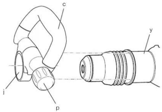
i j p c yFigure 3
text_image
D25721/ D25761 DeWALT CE 0.000 D33XXX - G s r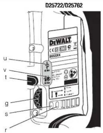
text_image
D25722/D25762 DEWALT CE 1000000 u v t g s r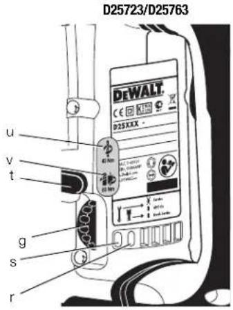
text_image
D25723/D25763 DEWALT. C E G K T S D25XXX - u v t g s r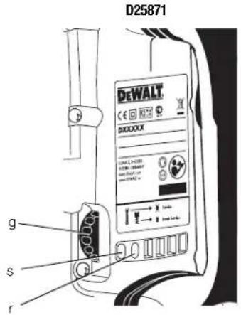
text_image
D25871 DEWALT C E I N O T DXXXXX G s r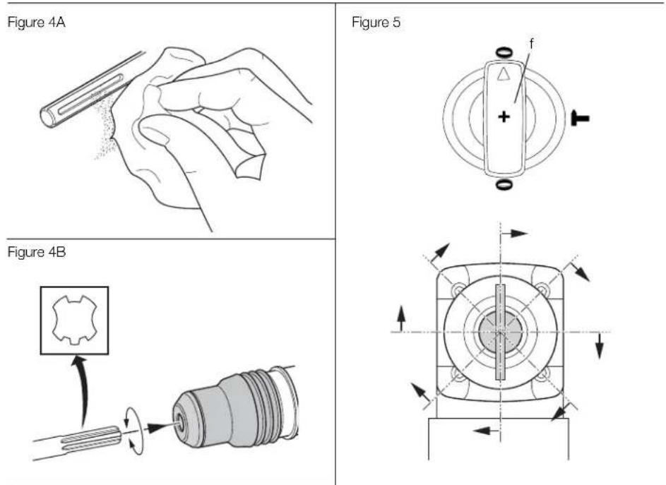
Figure 6
text_image
D25721/D25722/ D25723/D25761/ D25762/D25763 d C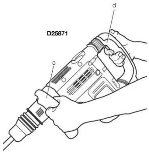
text_image
D25871 c dSDS MAX® KOMBINATIONS- & MEJSELHAMRE D25721, D25722, D25723, D25761, D25762, D25763, D25871
Tillykke!
KOMPLET DREJEMOMENTSTYRING (CTC) (FIG. 3) D25722/D25762
You have chosen a DEWALT tool. Years of experience, thorough product development and innovation make DEWALT one of the most reliable partners for professional power tool users.
Technical Data
| D25721 | D25722 | D25723 | D25761 | D25762 | D25763 | D25871 | ||||||||
| Voltage V | _DC | 230 | 230 | 230 | 230 | 230 | 230 | |||||||
| (U.K. & Ireland only) | V _DC | 230/115 | 230/115 | 230/115 | 230/115 | 230/115 | 230/115 | |||||||
| Type | 1 | 1 | 1 | 1 | 1 | 1 | ||||||||
| Power input | W | 1350 | 1400 | 1400 | 1500 | 1500 | 1500 | |||||||
| Impact energy(EPTA 05/2009) | J | 1.5–11 | 1.5–11 | 1.5–11 | 3–15.5 | 3–15.5 | 3–15.5 | |||||||
| Total drilling range in concrete: | ||||||||||||||
| solid bits | mm | 12–48 | 12–48 | 12–48 | 18–52 | 18–52 | 18–52 | |||||||
| core bits | mm | 40–115 | 40–125 | 40–125 | 40–150 | 40–150 | 40–150 | |||||||
| Optimum drilling range in concrete:solid bits | mm | 25–40 | 25–45 | 25–45 | 28–48 | 28–48 | 28–48 | |||||||
| Chisel positions | 24 | 24 | 24 | 24 | 24 | 24 | ||||||||
| Tool holder | SDS Max ^ | SDS Max ^ | SDS Max ^ | SDS Max ^ | SDS Max ^ | SDS Max ^ | ||||||||
| Weight | kg | 8.7 | 9.1 | 9.1 | 9.9 | 9.9 | 9.9 | |||||||
| L_PA (sound pressure) | dB(A) | 96 | 95 | 95 | 96 | 96 | 96 | |||||||
| K_PA (sound pressure uncertainty) | dB(A) | 3 | 3 | 3 | 3 | 3 | 3 | |||||||
| L_MX (sound power) | dB(A) | 107 | 106 | 106 | 107 | 107 | 107 | |||||||
| K_MX (sound power uncertainty) | dB(A) | 3 | 4 | 4 | 4 | 4 | 4 | |||||||
Vibration total values (triax vector sum) determined according to EN 60745:
| Vibration emission value an | ||||||||
| Drilling into concrete | ||||||||
| ah,HD= | m/s2 | 8.9 | 7.5 | 7.5 | 9.3 | 8.0 | 8.0 | - |
| Uncertainty K = m/s2 | 1.5 | 1.5 | 1.5 | 1.5 | 1.5 | 1.5 | - | |
| Vibration emission value ah | ||||||||
| Chiselling | ||||||||
| ah,Cheq= | m/s2 | 8.1 | 6.9 | 6.9 | 8.2 | 7.2 | 7.2 | 10.9 |
| Uncertainty K = m/s2 | 1.5 | 1.5 | 1.5 | 1.5 | 1.5 | 1.5 | 1.5 | |
The vibration emission level given in this information sheet has been measured in accordance with a standardised test given in EN 60745 and may be used to compare one tool with another. It may be used for a preliminary assessment of exposure.
WARNING: The declared vibration

emission level represents the main applications of the tool. However if the tool is used for different applications, with different accessories or poorly maintained, the vibration emission may differ. This may significantly increase the exposure level over the total working period.
An estimation of the level of exposure vibration should also take into account the times when the tool is switched off or when it is running but not actually doing the job. This may significantly reduce the exposure level over the total working period.
Identify additional safety measures to protect the operator from the effects of vibration such as: maintain the tool and the accessories, keep the hands warm, organisation of work patterns.
Fuses:
Europe 230 V tools 10 Amperes, mains
U.K. & Ireland 230 V tools 13 Amperes, in plugs
Definitions: Safety Guidelines
The definitions below describe the level of severity for each signal word. Please read the manual and pay attention to these symbols.

R: Indicates an imminently hazardous situation which, if not avoided, will result in death or serious injury.

NG: Indicates a potentially hazardous situation which, if not avoided, could result in death or serious injury.

N: Indicates a potentially hazardous situation which, if not avoided, may result in minor or moderate injury.
NOTICE: Indicates a practice not related to personal injury which, if not avoided, may result in property damage.

Denotes risk of electric shock.

Denotes risk of fire.
EC-Declaration of Conformity
MACHINERY DIRECTIVE

SDS MAX® COMBINATION & CHIPPING HAMMERS
D25721, D25722, D25723, D25761, D25762, D25763, D25871
DEWALT declares that these products described under Technical Data are in compliance with: 2006/42/EC, EN 60745-1, EN 60745-2-6.
D25871
2000/14/EC Electrical concrete breaker (hand held) m<= 15kg, Annex VIII; TÜV Rheinland Product Safety GmbH (0197), D-51105 Köln, Germany, Notified Body ID No.: 0197
Level of acoustic power according to 2000/14/EC (Article 12, Annex III, No. 10; m<=15 kg)
L_WA (measured sound power level) dB 101
L_WA (guaranteed sound power level) dB 105
These products also comply with Directive 2014/30/EU and 2011/65/EU. For more information, please contact DEWALT at the following address or refer to the back of the manual.
The undersigned is responsible for compilation of the technical file and makes this declaration on behalf of DEWALT.
text_image
H. JopsmannHorst Grossmann
Vice President Engineering DEWALT, Richard-Klinger-Straße 11, D-65510, Idstein, Germany
14.05.2014

WARNING: To reduce the risk of injury, read the instruction manual.
General Power Tool Safety Warnings

WARNING! Read all safety warnings and instructions. Failure to follow the warnings and instructions may result in electric shock, fire and/or serious injury.
ENGLISH
SAVE ALL WARNINGS AND INSTRUCTIONS FOR FUTURE REFERENCE
The term "power tool" in the warnings refers to your mains-operated (corded) power tool or battery-operated (cordless) power tool.
1) WORK AREA SAFETY
a) Keep work area clean and well lit.
Cluttered or dark areas invite accidents.
b) Do not operate power tools in explosive atmospheres, such as in the presence of flammable liquids, gases or dust. Power tools create sparks which may ignite the dust or fumes.
c) Keep children and bystanders away while operating a power tool. Distractions can cause you to lose control.
2) ELECTRICAL SAFETY
a) Power tool plugs must match the outlet. Never modify the plug in any way. Do not use any adapter plugs with earthed (grounded) power tools. Unmodified plugs and matching outlets will reduce risk of electric shock.
b) Avoid body contact with earthed or grounded surfaces such as pipes, radiators, ranges and refrigerators. There is an increased risk of electric shock if your body is earthed or grounded.
c) Do not expose power tools to rain or wet conditions. Water entering a power tool will increase the risk of electric shock.
d) Do not abuse the cord. Never use the cord for carrying, pulling or unplugging the power tool. Keep cord away from heat, oil, sharp edges or moving parts. Damaged or entangled cords increase the risk of electric shock.
e) When operating a power tool outdoors, use an extension cord suitable for outdoor use. Use of a cord suitable for outdoor use reduces the risk of electric shock.
f) If operating a power tool in a damp location is unavoidable, use a residual current device (RCD) protected supply. Use of an RCD reduces the risk of electric shock.
3) PERSONAL SAFETY
a) Stay alert, watch what you are doing and use common sense when operating a power tool. Do not use a power tool while you are tired or under the influence of drugs, alcohol or medication. A moment of inattention while operating power tools may result in serious personal injury.
b) Use personal protective equipment. Always wear eye protection. Protective equipment such as dust mask, non-skid safety shoes, hard hat, or hearing protection used for appropriate conditions will reduce personal injuries.
c) Prevent unintentional starting. Ensure the switch is in the off position before connecting to power source and/or battery pack, picking up or carrying the tool. Carrying power tools with your finger on the switch or energising power tools that have the switch on invites accidents.
d) Remove any adjusting key or wrench before turning the power tool on. A wrench or a key left attached to a rotating part of the power tool may result in personal injury.
e) Do not overreach. Keep proper footing and balance at all times. This enables better control of the power tool in unexpected situations.
i) Dress properly. Do not wear loose clothing or jewellery. Keep your hair, clothing and gloves away from moving parts. Loose clothes, jewellery or long hair can be caught in moving parts.
g) If devices are provided for the connection of dust extraction and collection facilities, ensure these are connected and properly used. Use of dust collection can reduce dust-related hazards.
4) POWER TOOL USE AND CARE
a) Do not force the power tool. Use the correct power tool for your application. The correct power tool will do the job better and safer at the rate for which it was designed.
b) Do not use the power tool if the switch does not turn it on and off. Any power tool that cannot be controlled with the switch is dangerous and must be repaired.
c) Disconnect the plug from the power source and/or the battery pack from the power tool before making any adjustments, changing accessories, or storing power tools. Such preventive safety measures reduce the risk of starting the power tool accidentally.
d) Store idle power tools out of the reach of children and do not allow persons unfamiliar with the power tool or these instructions to operate the power tool. Power tools are dangerous in the hands of untrained users.
e) Maintain power tools. Check for misalignment or binding of moving parts, breakage of parts and any other condition that may affect the power tool's operation. If damaged, have the power tool repaired before use. Many accidents are caused by poorly maintained power tools.
f) Keep cutting tools sharp and clean. Properly maintained cutting tools with sharp cutting edges are less likely to bind and are easier to control.
g) Use the power tool, accessories and tool bits etc., in accordance with these instructions taking into account the working conditions and the work to be performed. Use of the power tool for operations different from those intended could result in a hazardous situation.
5) SERVICE
a) Have your power tool serviced by a qualified repair person using only identical replacement parts. This will ensure that the safety of the power tool is maintained.
Additional Safety Instructions for Rotary Hammers
- Wear ear protectors. Exposure to noise can cause hearing loss.
- Use auxiliary handle(s), if supplied with the tool. Loss of control can cause personal injury.
- Hold power tool by insulated gripping surfaces, when performing an operation where the cutting accessory may contact hidden wiring or its own cord. Cutting accessory contacting a "live" wire may make exposed metal parts of the power tool "live" and could give the operator an electric shock.
Residual Risks
The following risks are inherent to the use of rotary and chipping hammers:
-
Injuries caused by touching the rotating parts or hot parts of the tool
In spite of the application of the relevant safety regulations and the implementation of safety devices, certain residual risks cannot be avoided. These are: -
Impairment of hearing.
– Risk of squeezing fingers when changing the accessory. - Health hazards caused by breathing dust developed when working in concrete and/or masonry.
Markings on Tool
The following pictograms are shown on the tool:

Read instruction manual before use.

Wear ear protection.

Wear eye protection.

Clutch Setting 40 Nm is designed for most drilling applications.

Clutch Setting 80 Nm is designed for higher torque applications.

Red service indicator LED. For detailed description see under Service Indicator LED's.

Yellow service indicator LED. For detailed description see under Service Indicator LED's.
DATE CODE POSITION (FIG. 1)
The Date Code (w), which also includes the year of manufacture, is printed into the housing.
Example:
2014 XX XX
Year of Manufacture
Package Contents
The package contains:
1 Rotary hammer
(D25721, D25722, D25723, D25761, D25762, D25763)
or
1 Chipping Hammer (D25871)
1 Side handle
1 Kitbox (K-models only)
1 Pointed chisel (only D25871)
1 Instruction manual
1 Exploded drawing
- Check for damage to the tool, parts or accessories which may have occurred during transport.
ENGLISH
• Take the time to thoroughly read and understand this manual prior to operation.
Description (fi g. 1A, 1B, 2A, 2B)
WARNING: Never modify the power tool or any part of it. Damage or personal injury could result.
a. Trigger switch (D25721, D25722, D25723, D25761, D25762, D25763) On/off rocker switch (D25871)
b. Lock-on slider (D25721, D25722, D25723, D25762, D25763)
c. Side handle
d. Main handle
e. Active vibration control
f. Mode selector switch
g. Electronic speed and impact control dial
h. Clamp wheel
i. Side handle clamp
j. Steel ring
k. Bush
I. Tool holder
m. Pin
n. Collar
o. Locking sleeve
p. Side handle knob
INTENDED USE
D25721, D25722, D25723, D25761, D25762, D25763
Your rotary hammer has been designed for professional rotary drilling and chipping applications.
D25871
Your chipping hammer has been designed for professional chipping, chiselling and demolition applications.
DO NOT use under wet conditions or in presence of flammable liquids or gases.
These hammers are professional power tools.
DO NOT let children come into contact with the tool. Supervision is required when inexperienced operators use this tool.
- This product is not intended for use by persons (including children) suffering from diminished physical, sensory or mental abilities; lack of experience, knowledge or skills unless they are supervised by a person responsible for their safety. Children should never be left alone with this product.
Soft Start Feature
D25722, D25723, D25761, D25762, D25763
The soft start feature allows the tool to accelerate slowly, thus preventing the drill bit from walking off the intended hole position when starting.
The soft start feature also reduces the immediate torque reaction transmitted to the gearing and the operator if the hammer is started with the drill bit in an existing hole.
Electronic Speed and Impact Control (fi g. 1, 3)
The electronic speed and impact control (g) offers the following advantages:
– use of smaller accessories without risk of breakage;
- minimised break-out when chiselling or drilling in soft or brittle materials;
- optimal tool control for precise chiselling.
Torque Limiting Clutch

WARNING: The user must always maintain a firm grip on the tool when in operation.
The torque limiting clutch reduces the maximum torque reaction transmitted to the operator in case of jamming of a drill bit. This feature also prevents the gearing and electric motor from stalling.
NOTICE: Always turn the tool off before changing torque control settings or damage to tool may result.
COMPLETE TORQUE CONTROL (CTC) (FIG. 3) D25722/D25762
Complete Torque Control (CTC) offers the user a two-stage mechanical clutch with adjustable torque options. Adjusting the torque provides increased control for various applications.
The low setting (40 Nm) allows the tool to operate at a reduced torque level increasing control for many solid drilling applications. The high setting (80 Nm) is available for more demanding applications such as core drilling and the use of large diameter solid bits.
Refer to Setting the Two Stage Mechanical Clutch for more information.
ULTIMATE TORQUE CONTROL (UTC) D25723/D25763
In addition to the two-stage mechanical clutch, Ultimate Torque Control (UTC) offers increased user comfort and safety through an on-board, anti-rotation technology capable of detecting if
the user loses control of the hammer. When a jam is detected, the torque and speed are reduced instantly. This feature prevents self rotation of the tool reducing the occurrence of wrist injuries.
Service Indicator LEDs (fi g. 3)
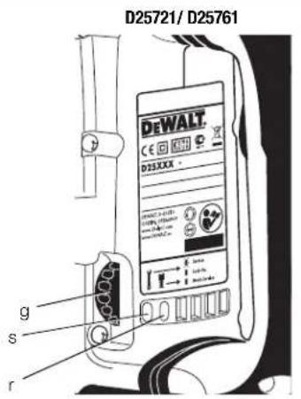
The yellow brushwear indicator LED (s) lights up when the carbon brushes are nearly worn out to indicate that the tool needs servicing within the next 8 hours of use.
D25721, D25722, D25723, D25761, D25762, D25763
The red service indicator LED (r) lights up if the lock-on button (b) is used in any mode except the chipping mode. On models fitted with Ultimate Torque Control (UTC), the red LED indicator (r) lights up if the anti-rotational device is activated. The red indicator starts to flash if there is a fault with the tool or the brushes have completely worn out (refer to
Brushes under Maintenance).
D25871
The red service indicator LED (r) lights up if there is a fault with the tool or the brushes have completely worn out (refer to Brushes under Maintenance).
Fully Vibration-dampened Main Handle (fi g. 1)
The dampers in the main handle (d) absorb the vibrations transmitted to the user. This improves user comfort during the operation.
Electrical Safety
The electric motor has been designed for one voltage only. Always check that the power supply corresponds to the voltage on the rating plate.

Your DEWALT tool is double insulated in accordance with EN 60745; therefore no earth wire is required.

VG: 115 V units have to be operated via a fail-safe isolating transformer with an earth screen between the primary and secondary winding.
If the supply cord is damaged, it must be replaced by a specially prepared cord available through the DEWALT service organisation.
Mains Plug Replacement (U.K. & Ireland Only)
If a new mains plug needs to be fitted:
- Safely dispose of the old plug.
- Connect the brown lead to the live terminal in the plug.
- Connect the blue lead to the neutral terminal.

WARNING: No connection is to be made to the earth terminal.
Follow the fitting instructions supplied with good quality plugs. Recommended fuse: 13 A.
Using an Extension Cable
If an extension cable is required, use an approved 3-core extension cable suitable for the power input of this tool (see technical data). The minimum conductor size is 1.5mm^2 ; the maximum length is 30m .
When using a cable reel, always unwind the cable completely.
ASSEMBLY AND ADJUSTMENTS

WARNING: To reduce the risk of injury, turn unit off and disconnect machine from power source before installing and removing accessories, before adjusting or changing set-ups or when making repairs. Be sure the trigger switch is in the OFF position. An accidental start-up can cause injury.

WARNING: Tool bits may be hot and gloves should be worn when changing or removing them to avoid personal injury.
Assembling and Fitting the Side Handle (fi g. 2A, 2B)
The side handle (c) can be mounted on either side of the machine to suit both right- and left-handed users.

WARNING: Always operate the tool with the side handle properly assembled.
D25721, D25722, D25723, D25761, D25762, D25763 MOUNTING IN FRONT POSITION (FIG. 2A)
- Snap the steel ring (j) over the collar (n) behind the tool holder (l). Squeeze both ends together, mount the bush (k) and insert the pin (m).
- Place the side handle clamp (i) and screw on the clamp wheel (h). Do not tighten.

WARNING: Once assembled, the side handle clamp should never be removed.
- Screw the side handle (c) into the bush (k) and then into clamp wheel. Tighten securely.
ENGLISH
-
Rotate the side handle mounting assembly to the desired position. For drilling horizontally with a heavy drill bit, we recommend to place the side handle at an angle of approximately 20^ for optimum control.
-
Lock the side handle mounting assembly in place by tightening the clamp wheel (h).
D25871 (FIG. 2B)
- Unscrew the side handle knob (p).
- Slide the side handle assembly onto the machine locating the steel ring (j) in the mounting area (y). The correct position of the side handle is between head and middle of the tube.
- Adjust the side handle (c) to the desired angle.
- Slide and rotate the side handle to the desired position.
- Lock the side handle in place by tightening the knob (p).
Inserting and Removing SDS Max® Accessories (fi g. 1, 4A, 4B)
This machine uses SDS Max ^® bits and chisels (refer to the inset in figure 4B for a cross-section of an SDS Max ^® bit shank).
- Clean the bit shank.
- Pull back the locking sleeve (o) and insert the bit shank.
- Turn the bit slightly until the sleeve snaps into position.
- Pull on the bit to check if it is properly locked. The hammering function requires the bit to be able to move axially several centimetres when locked in the tool holder.
- To remove a bit pull back the tool holder locking sleeve/collar (o) and pull the bit out of the tool holder (l).
Selecting the Operating Mode (fi g. 1)

Hammerdrilling:
D25721, D25722, D25723, D25761, D25762, D25763
for concrete, brick, stone and masonry drilling operations.

Hammering only:
for chiselling and demolition applications. In this mode the tool can also be used as a lever to free a jammed drill bit.
- To select the operating mode, rotate the mode selector switch (f) until it points to the symbol of the required mode.
It may be necessary to twist the tool holder (l) slightly to allow the mode selector switch (f) to pass the 0 position. - Check that the mode selector switch (f) is locked in place.
Indexing the Chisel Position (fi g. 5)
The chisel can be indexed and locked into 24 different positions.
- Rotate the mode selector switch (f) until it points towards the 0 position.
- Rotate the chisel in the desired position.
- Set the mode selector switch (f) to the "hammering only" position.
- Twist the chisel until it locks in position.
Setting the Electronic Speed and Impact Control Dial (fi g. 1, 3)
Turn the dial (g) to the desired level. Turn the dial upwards for higher speed and downwards for lower speed. The required setting is a matter of experience, e.g.
- when chiselling or drilling in soft, brittle materials or when minimum break-out is required, set the dial to a low setting;
- when breaking or drilling in harder materials, set the dial to a high setting.
Setting the Two Stage Mechanical Clutch (fi g. 3)
D25722, D25723, D25762, D25763
NOTICE: Always turn the tool off before changing torque control settings or damage to the tool may result.
Move the torque control lever (t) to setting 40 Nm or 80 Nm as needed for application.
- Clutch Setting 40 Nm (u) is designed for most drilling applications and is designed to easily clutch out when the drill bit encounters re-bar or other foreign substances.
- Clutch Setting 80 Nm (v) is designed for higher torque applications such as core-bits and deep hole drilling and is designed to clutch out at a higher torque threshold.
NOTE: If it is not possible to select position 80 Nm run the unit under load and try again.
Each time the tool is plugged in, it will automatically default to clutch setting 1 into clutch setting 40 Nm (u), the most sensitive setting.
OPERATION
Instructions for Use

VG: Always observe the safety instructions and applicable regulations.

WARNING: To reduce the risk of injury, turn unit off and disconnect machine from power source before installing and removing accessories, before adjusting or changing set-ups or when making repairs. Be sure the trigger switch is in the OFF position. An accidental start-up can cause injury.

WARNING: Tool bits may be hot and gloves should be worn when changing or removing them to avoid personal injury.

- Be aware of the location of pipework and wiring.
- Apply only a gentle pressure to the tool (approximately 20kg ). Excessive force does not speed up drilling but decreases tool performance and may shorten tool life. - Always hold the tool firmly with both hands and ensure a secure stance. Always operate the tool with the side handle properly assembled.
NOTE: Operating temperature is -7^ to +40^ C ( 19^ to 104^ F). Using the tool outside of this temperature range will decrease the life of the tool.
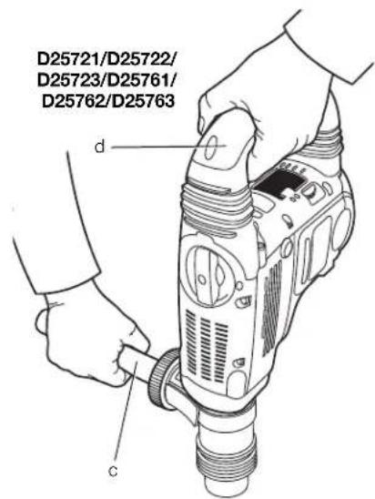
Proper Hand Position (fi g. 6)

NG: To reduce the risk of serious personal injury, ALWAYS use proper hand position as shown.

VG: To reduce the risk of serious personal injury, ALWAYS hold securely in anticipation of a sudden reaction.
Proper hand position requires one hand on the side handle (c), with the other hand on the main handle (d).
Switching On and Off (fi g. 1)
D25721, D25722, D25723, D25761, D25762, D25763
To turn the tool on, depress the trigger switch (a).
To stop the tool, release the trigger switch.
D25721, D25722, D25723, D25762, D25763
The lock-on slider (b) allows the trigger switch (a) to be locked on in chiselling mode only. If the lock-on button is activated in drilling mode, as a feature the tool will switch off automatically.
To turn the tool on, press the trigger switch (a).
To stop the tool, release the switch.
For continuous operation, press and hold down the switch (a), slide the lock-on button (b) upwards and release the switch.
To stop the tool in continuous operation, press the switch briefly and release it. Always switch off the tool when work is finished and before unplugging.
D25871
To turn the tool on, press the on/off rocker switch (a) at the lower part of the trigger.
To stop the tool, press the on/off rocker switch at the upper part of the trigger.
Hammerdrilling
To turn the tool on, press the on/off switch (a).
To stop the tool, release the switch.
Drilling with a Solid Bit (fi g. 1)
D25721, D25722, D25723, D25761, D25762, D25763
- Insert the appropriate drill bit.
- Set the mode selector switch (f) to the hammerdrilling position.
- Set the electronic speed and impact control dial (g).
- Fit and adjust the side handle (c).
- Mark the spot where the hole is to be drilled.
- Place the drill bit on the spot and switch on the tool.
- Always switch off the tool when work is finished and before unplugging.
Drilling with a Core Bit (fi g. 1)
- Insert the appropriate core bit.
- Assemble the centerdrill into the core bit.
- Set the mode selector switch (f) to the hammerdrilling position.
- Turn the electronic speed and impact control dial (g) to a medium or high speed setting.
ENGLISH
- Fit and adjust the side handle (c).
- Place the centerdrill on the spot and switch on the tool. Drill until the core penetrates into the concrete approximately 1 cm.
- Stop the tool and remove the centerdrill. Place the core bit back into the hole and continue drilling.
- When drilling through a structure thicker than the depth of the core bit, break away the round cylinder of concrete or core inside the bit at regular intervals.
To avoid unwanted breaking away of concrete around the hole, first drill a hole the diameter of the centerdrill completely through the structure. Then drill the cored hole halfway from each side. - Always turn the tool off when work is finished and before unplugging.
Chipping and Chiselling (fi g. 1)
- Insert the appropriate chisel and rotate it by hand to lock it into one of 24 positions.
- Set the mode selector switch (f) to the hammering only position.
- Set the electronic speed and impact control dial (g).
- Fit and adjust the side handle (c).
- Turn the tool on and start working.
- Always turn the tool off when work is finished and before unplugging.
MAINTENANCE
Your DEWALT power tool has been designed to operate over a long period of time with a minimum of maintenance. Continuous satisfactory operation depends upon proper tool care and regular cleaning.
WARNING: To reduce the risk of injury, turn unit off and disconnect machine from power source before installing and removing accessories, before adjusting or changing set-ups or when making repairs. Be sure the trigger switch is in the OFF position. An accidental start-up can cause injury.
This machine is not user-serviceable. Take the tool to an authorised DEWALT repair agent after approximately 150 hours of use. If problems occur before this time, contact an authorised DEWALT repair agent.
Brushes (fi g. 3)
The carbon brushes are not user-serviceable. Take the tool to an authorized DEWALT repair agent.
The yellow brushwear indicator LED (s) lights up when the carbon brushes are nearly worn out. After a further 8 hours of use or after the brushes have completely worn out, the motor will automatically be shut off.
Tool maintenance needs to be carried out as soon as the service indicator (r) lights up.

Lubrication
Your power tool requires no additional lubrication.

Cleaning
WARNING: Blow dirt and dust out of the main housing with dry air as often as dirt is seen collecting in and around the air vents. Wear approved eye protection and approved dust mask when performing this procedure.
WARNING: Never use solvents or other harsh chemicals for cleaning the non-metallic parts of the tool. These chemicals may weaken the materials used in these parts. Use a cloth dampened only with water and mild soap. Never let any liquid get inside the tool; never immerse any part of the tool into a liquid.
Optional Accessories
WARNING: Since accessories, other than those offered by DEWALT, have not been tested with this product, use of such accessories with this tool could be hazardous. To reduce the risk of injury, only DEWALT, recommended accessories should be used with this product.
Various types of SDS Max ^® drill bits and chisels are available as an option.
Consult your dealer for further information on the appropriate accessories.
Protecting the Environment
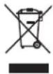
Separate collection. This product must not be disposed of with normal household waste.
Should you find one day that your DEWALT product needs replacement, or if it is of no further use to you, do not dispose of it with household waste. Make this product available for separate collection.

Separate collection of used products and packaging allows materials to be recycled and used again. Re-use of recycled materials helps prevent environmental pollution and reduces the demand for raw materials.
Local regulations may provide for separate collection of electrical products from the household, at municipal waste sites or by the retailer when you purchase a new product.
DEWALT provides a facility for the collection and recycling of DeWALT products once they have reached the end of their working life. To take advantage of this service please return your product to any authorised repair agent who will collect them on our behalf.
You can check the location of your nearest authorised repair agent by contacting your local DEWALT office at the address indicated in this manual. Alternatively, a list of authorised DEWALT repair agents and full details of our after-sales service and contacts are available on the Internet at:
www.2helpU.com.
GUARANTEE
DEWALT is confident of the quality of its products and offers an outstanding guarantee for professional users of the product. This guarantee statement is in addition to and in no way prejudices your contractual rights as a professional user or your statutory rights as a private non-professional user. The guarantee is valid within the territories of the Member States of the European Union and the European Free Trade Area.
• 30 DAY NO RISK SATISFACTION GUARANTEE •
If you are not completely satisfied with the performance of your DEWALT tool, simply return it within 30 days, complete with all original components, as purchased, to the point of purchase, for a full refund or exchange. The product must have been subject to fair wear and tear and proof of purchase must be produced.
• ONE YEAR FREE SERVICE CONTRACT •
If you need maintenance or service for your DEWALT tool, in the 12 months following purchase, you are entitled to one service free of charge. It will be undertaken free of charge at an authorised DEWALT repair agent. Proof of purchase must be produced. Includes labour. Excludes accessories and spare parts unless failed under warranty.
• ONE YEAR FULL WARRANTY •
If your DEWALT product becomes defective due to faulty materials or workmanship within 12 months from the date of purchase, DEWALT guarantees to replace all defective parts free of charge or – at our discretion – replace the unit free of charge provided that:
• The product has not been misused;
- The product has been subject to fair wear and tear;
• Repairs have not been attempted by unauthorised persons;
• Proof of purchase is produced;
- The product is returned complete with all original components.
If you wish to make a claim, contact your seller or check the location of your nearest authorised DEWALT repair agent in the DEWALT catalogue or contact your DEWALT office at the address indicated in this manual. A list of authorised DEWALT repair agents and full details of our after-sales service is available on the Internet at: www.2helpU.com.
MARTILLOS SDS MÁX® COMBINACIÓN Y MARTILLOS DE SOLDADOR D25721, D25722, D25723, D25761, D25762, D25763, D25871
¡Enhorabuena!
Vice President Engineering
WAARSCHUWING! Lees alle
BEWAAR ALLE WAARSCHUWINGEN EN INSTRUCTIES ALS TOEKOMSTIG REFERENTIEMATERIAAL
POSITIE DATUMCODE (AFB. [FIG.] 1)
Service-indicatie-LED's (afb. 3)
1) SIKKERHET PÅ ARBEIDSOMRÅDET
DATUMKODPLACERING (FIG. 1)
text_image
Exploded view diagram of a mechanical assembly with numbered parts and labeled dimensions in millimeters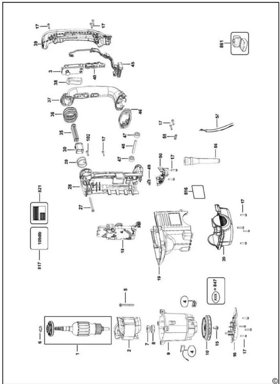
text_image
Exploded view diagram of a mechanical assembly with numbered parts and labeled dimensionsD25721K
text_image
Exploded view diagram of a mechanical assembly with numbered parts and labeled dimensions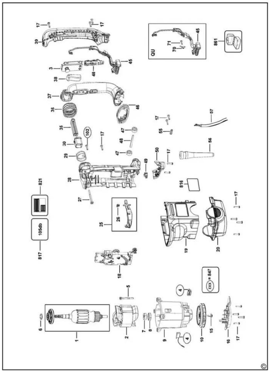
text_image
Exploded view diagram of a mechanical assembly with numbered parts and labeled parts such as engine, motor, and housing.D25722K
Патрон ПЕРФОРАТОР
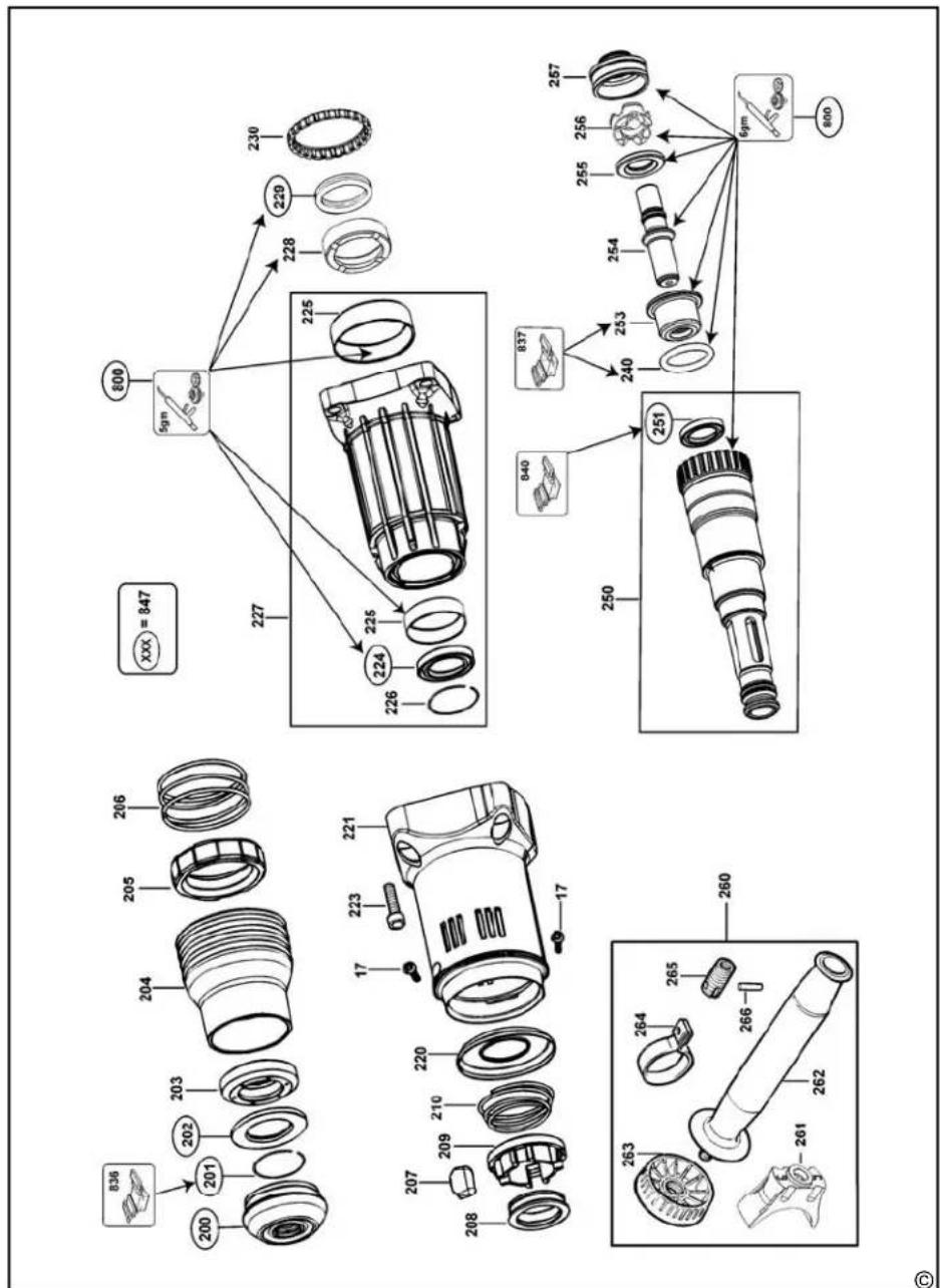
text_image
XXX = 847 230 229 228 800 5gm 225 224 226 227 257 256 255 254 253 240 837 840 251 250 260 265 266 261 262 263 264 263 17 17 17 200 201 202 203 204 205 206 207 208 209 210 211 212 213 214 215 216 217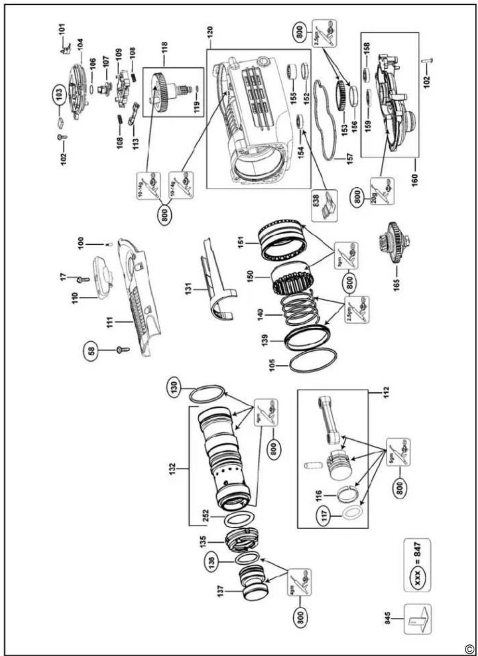
text_image
Exploded view diagram of a mechanical assembly with numbered components and labeled partsnatural_image
Pure horizontal line with endpoints and no text or symbols| 181 |
| Belgique et Luxembourg België en Luxemburg | DEWALT - Belgium BVBAEgide Walschaertsstraat 162800 Mechelen | Tel: NL 32 15 47 37 63Tel: FR 32 15 47 37 64Fax: 32 15 47 37 99 | www.dewalt.beenduser.BE@sbdinc.com |
| Danmark D | EWALTRoskildevej 222620 Albertslund | Tel: 70 20 15 11Fax: 70 22 49 10 | www.dewalt.dkkundeservice.dk@sbdinc.com |
| Deutschland D | EWALTRichard Klinger Str. 1165510 Idstain | Tel: 06126-21-1Fax: 06126-21-2770 | www.dewalt.deinfobfgo@sbdinc.com |
| Ελλάς D | EWALT (Ελλάς) A.E.ΕΔΡΑ-ΓΡΑΦΕΙΑ : Στράβωνος 7& Λ. Βουλιαγμένης, Γλυφάδα 166 74, ΑθήναSERVICE : Ημερος Τόπος 2 (Χάνι Αδάμ) –193 00 Ασπρόπυργος | Thy: 00302108981616Φαξ: 00302108983570 | www.dewalt.grGreece.Service@sbdinc.com |
| España D | EWALT Ibérica, S.C.A.Parc de Nogocios “Mas Blau”Edificio Muntadas, c/Bergadá, I, Of. A608820 El Prat de Llobregat (Barcelona) | Tel: 934 797 400Fax: 934 797 419 | www.dewalt.crespuesta.postvonta@sbdinc.com |
| France D | EWALT5, allée des HêtresBP 30084, 69579 Limonost Codex | Tel: 04 72 20 39 20Fax: 04 72 20 39 00 | www.dewalt.frscufr@sbdinc.com |
| SchweizSuisseSvizzera | DEWALTIn der Luberzen 428902 Urdorf | Tel: 044 - 755 60 70Fax: 044 - 730 70 67 | www.dewalt.chservice@rofoag.ch |
| Ireland D | EWALTCalpe House Rock HillBlack Rock, Co. Dublin | Tel: 00353-2781900Fax: 00353-2781811 | www.dewalt.ie |
| Italia D | EWALTvia Energypark20871 Vimercate (MB), IT | Tel: 800-01435339 039 9590200Fax: 39 039 9590313 | www.dewalt.it |
| Nederlands | DEWALT Netherlands BVHollurn Noordweg 356121 RE BORN, Postbus 83, 6120 AB BORN | Tel: 31 164 283 063Fax: 31 164 283 200 | www.dewalt.nl |
| Norge | DEWALTPostboks 4613, Nydalen0405 Oslo | Tel: 22 90 99 10Fax: 45 25 08 00 | www.dewalt.nokundeservice.no@sbdinc.com |
| Österreich | DEWALTWerkzeug Vertriebsges m.b.HOberlaaerstrasse 248, A-1230 Wien | Tel: 01 - 66116 - 0Fax: 01 - 66116 - 614 | www.dewalt.atservice.austria@sbdinc.com |
| Portugal | DEWALT Limited, SARLCentro de Escritórios de Sintra AvonidaAlmirante Gago Coutinho, 132/134, Edificio 142710-418 Sintra | Tel: 214 66 75 00Fax: 214 66 75 80 | www.dewalt.ptresposta.posvenda@sbdinc.com |
| Suomi D | EWALTTekniikantie 12, 02150 Espoo02150 Espoo, Finland | Puh: 010 400 43 33Faksi: 0800 411 340 | www.dewalt.fiasiakaspalvelu.fi@sbdinc.com |
| Sverige D | EWALTBox 94431 22 Mölndal | Tel: 031 68 60 60Fax: 031 68 60 08 | www.dewalt.sekundservice.so@sbdinc.com |
| Türkiye | KALE Hirdavat ve Makina A.Ş.Deflerdar Mah. Savaklar Cad. No:15Edirnekapi / Eyüp / İSTANBUL 34050TÜRKİYE | Tel: 0212 533 52 55Faks: 0212 533 10 05 | www.dewalt.com.tr |
| UnitedKingdom | DEWALT, 210 Bath Road;Slough, Barks SL1 3YD | Tel: 01753-567055Fax: 01753-572112 | www.dewalt.co.ukemeaservice@sbdinc.com |
| Australia | DEWALT82 Taryn Drive, EppingVIC 3076 Australia | Tel: Aust 1800 338 002Tel: NZ 0800 339 258 | www.dewalt.com.auwww.dewalt.co.nz |
| Middle East Africa | DEWALTP.O. Box - 17164,Jebel Ali Free Zone (South), Dubai, UAE | Tel: 971 4 812 7400Fax: 971 4 2822765 | www.dewalt.aeService.MEA@sbdinc.com |