USER MANUAL PLM5120 MAKITA
natural_image
Technical line drawing of a mechanical component with a circular base and lever mechanism (no text or symbols)
2A
2B
natural_image
Line drawing of a mechanical component with a tool inserted, no text or symbols present
2C
natural_image
Line drawing of a car tire being adjusted to lift a tire, showing mechanical components (no text or symbols)
2D
natural_image
Pure technical line drawing of a mechanical component or bracket (no text or symbols)
2E
natural_image
Pure technical line drawing of a mechanical component without any text, numbers, or symbols
2F
natural_image
Line drawing of a bicycle support structure with no text or symbols
2G
natural_image
Technical line drawing of a mechanical bracket or frame structure (no text or symbols)
2H
natural_image
Line drawing of a mechanical device with a tire and lever, no text or symbols present
3A 3B
natural_image
Technical line drawing of a mechanical assembly with no visible text or symbols
4A 4B
natural_image
Line drawing of a mechanical tool or device with a lever and attached components (no text or symbols)
5
natural_image
Line drawing of hands holding a clipboard with tools, no text or symbols present
6A
natural_image
Technical line drawing of a mechanical component with springs and brackets (no text or symbols)
6B 6C
natural_image
Line drawing of a car seatbelt with a handle and wheel rim (no text or symbols)
natural_image
Line drawing of hands holding a clipboard with tools, no text or symbols present
7A 7B
natural_image
Line drawing of a car interior showing dashboard, steering wheel, and battery compartment (no text or symbols)
8A 8B
natural_image
Technical line drawing of a mechanical component with labeled parts (no text or symbols beyond the number 18)
natural_image
Line drawing of a robotic arm with articulated joints and chains (no text or symbols)
8C 8D
natural_image
Line drawing of a chair seat with adjustable arm and seatbelt, showing motion direction (no text or symbols)
9 10A PLM5120
10B PLM5121 11
natural_image
Exploded view diagram of a mechanical assembly with labeled components (no text or symbols)
ENGLISH (Original instructions)
Explanation of general view
| 1. Brake control handle | 7. Cable clamp | 13. Oil cap |
| 2. Upper handle | 8. Height adjusting lever | 14. Starter handle |
| 3. Self-drive control handle | 9. Deck | 15. Bolt |
| 4. Choke lever | 10. Sideward flap | 16. Washer |
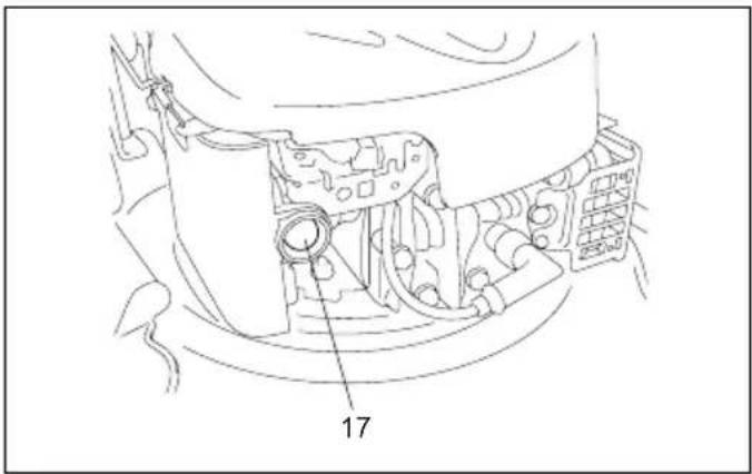
| 5. Rope guide | 11. Spark plug | 17. Primer bulb |
| 6. Locking knob | 12. Fuel cap | 18. Screw |

WARNING:
For your own safety please read this manual before attempting to operate your new unit. Failure to follow instructions can result in serious personal injury. Spend a few moments to familiarize yourself with your mower before each use.
1. SYMBOLS MARKED ON THE PRODUCT

Read operator's manual.

Keep bystanders away.
Pay more attention to the operator's hands and feet to avoid injury.
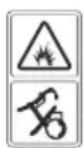
Fuel is flammable, keep fire away. Do not add fuel with running machine.

Toxic fumes; Don't operate inside house.

When mowing, please wear the glasses and ear plugs to defend the operator himself.

When repairing, please pick up the spark plug and then repair it according to the operational manual.

Caution: Engine hot.
2. GENERAL SAFETY RULES

WARNING: When using petrol tools, basic safety precautions, including the following, should always be followed to reduce the risk of serious personal injury and/or damage to the unit. Read all these instruction before operating this product and retain these instructions for future reference.

WARNING: This machine produces an electromagnetic field during operation. This field may under some circumstances interfere with active or passive medical implants. To reduce the risk of serious or fatal injury, we recommend persons with medical implants to consult their physician and the medical implant manufacturer before operating this machine.
Training
- Read the instructions carefully. Be familiar with the controls and the proper use of the equipment.
- Never allow children or people unfamiliar with these instructions to use the lawn mower. Local regulations can restrict the age of the operator.
- Never mow while people, especially children, or pets are nearby.
- Keep in mind that the operator or user is responsible for accidents or hazards occurring to other people or their property.
Preparation
- If petrol is spilled, do not attempt to start the engine but move the machine away from the area of spillage and avoid creating any source of ignition until petrol vapors have dissipated.
- Replace all fuel tank and container caps securely.
- Replace faulty silencers.
- Before using, always visually inspect to see that the blades, blade bolts and cutter assembly are not worn or damaged. Replace worn or damaged blades and bolts in sets to preserve balance.
Operation
- Do not operate the engine in a confined space where dangerous carbon monoxide fumes can collect.
- Mow only in daylight or in good artificial light.
- Avoid operating the equipment in wet grass, where feasible.
• Always be sure of your footing on slopes.
- Walk, never run.
- For wheeled rotary machines, mow across the face of slopes, never up and down.
- Exercise extreme caution when changing direction on slopes.
- Do not mow excessively steep slopes.
- Use extreme caution when reversing or pulling the lawn mower towards you.
- Stop the blade(s) if the lawn mower has to be tilted for transportation when crossing surfaces other than grass, and when transporting the lawn mower to and from the area to be mowed.
- Never operate the lawn mower with defective guards, or without safety devices, for example deflectors and/or grass catchers, in place.
- Do not change the engine governor settings or overspeed the engine.
- Disengage all blades and drive clutches before starting the engine.
- Start the engine carefully according to instructions and with feet well away from the blade(s).
- Do not tilt the lawn mower when starting the engine.
- Do not start the engine when standing in front of the discharge chute.
- Do not put hands or feet near or under rotating parts. Keep clear of the discharge opening at all times.
- Never pick up or carry a lawn mower while the engine is running.
-
Stop the engine and disconnect the spark plug wire, make sure that all moving parts have come to a complete stop and, where a key is fitted remove the key:
-
Before clearing blockages or unclogging chute.
- Before checking, cleaning or working on the lawn mower.
- After striking a foreign object. Inspect the lawn mower for damage and make repairs before restarting and operating the lawn mower.
- If lawn mower starts to vibrate abnormally (check immediately).
- Stop the engine and disconnect the spark plug wire, make sure that all moving parts have come to a complete stop and, where a key is fitted remove the key:
- Whenever you leave the lawn mower.
- Before refueling.
- Reduce the throttle setting during engine shut down and, if the engine is provided with a shut-off valve, turn the fuel off at the conclusion of mowing.
Maintenance and storage
- Keep all nuts, bolts and screws tight to be sure the equipment is in safe working condition.
- Never store the equipment with petrol in the tank inside a building where fumes can reach an open flame or spark.
- Allow the engine to cool before storing in any enclosure.
- To reduce the fire hazard, keep the engine, silencer, battery compartment and petrol storage area free of grass, leaves, or excessive grease.
- Check the grass catcher frequently for wear or deterioration.
- Replace worn or damaged parts for safety.
- If the fuel tank has to be drained, this should be done outdoors.

WARNING: Do not touch rotating blade.

WARNING: Refuel in a well ventilated area with
the engine stopped.
3. PARTS DESCRIPTION (Fig. 1A & 1B)
Including
A: Spark plug wrench
B: Discharge channel
4. TECHNICAL DATA
| Model PLM5121 PLM5120 | | |
| Engine type B&S675EX Series, ReadyStart, 126T B&S625E Series, 122T | |
| Self-Propelled Yes No | | |
| Engine Displacement 190 cm | ^3 | 190 cm^3 |
| Blade Width 510 mm | 510 mm | |
| Rated Speed | 2,800/min | 2,800/min |
| Fuel Tank Capacity | 1.0 L | 1.0 L |
| Net Weight | 31.7 kg | 28 kg |
| Height adjustment: | 25-70 mm, 5 adjustment |
| L_pA (SPL) at the site of the user (k = 3 dB (A)) | 79.2 dB (A) | 78.9 dB (A) |
| Guaranteed Sound Power level L_wA | 98 dB (A) | 98 dB (A) |
| Vibration (k = 1.5 m/ s^2 ) | 2.305 m/ s^2 | 2.056 m/ s^2 |
5. ASSEMBLY
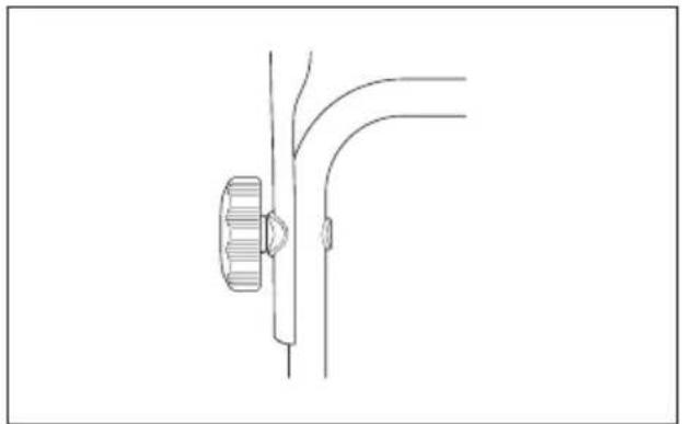
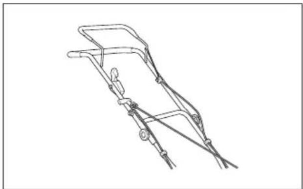
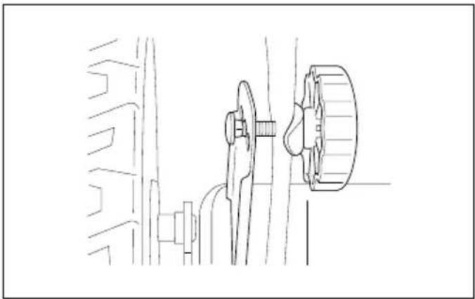
5-1 ASSEMBLY THE FOLDING HANDLE
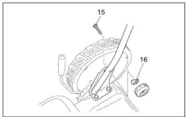
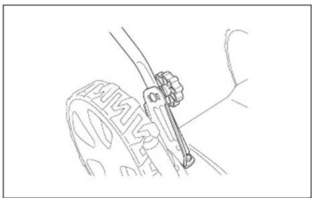
- Fix the lower handlebars into the unit body with locking knobs as shown. (Fig. 2A, Fig. 2B, Fig. 2C, Fig. 2D)
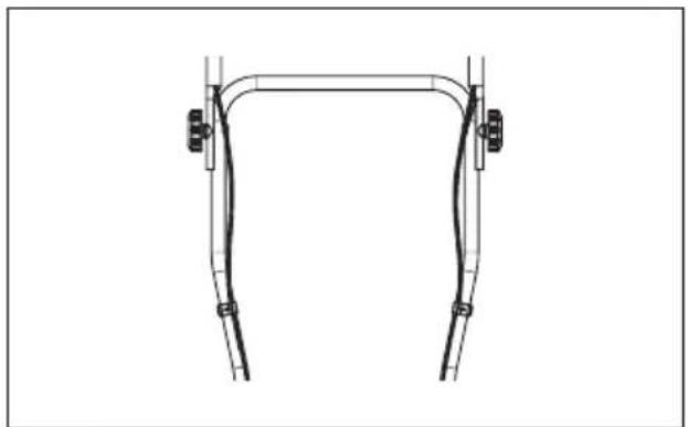
- Connect the upper handle and the lower handle with the locking knob. (Fig. 2E, Fig. 2F, Fig. 2G)
- Attach the cable-clamp to the position shown and then attach the cable. (Fig. 2H)
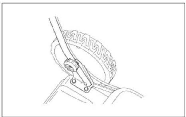
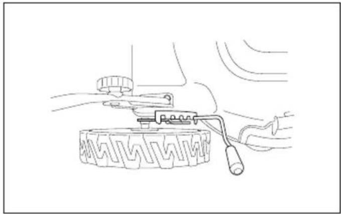
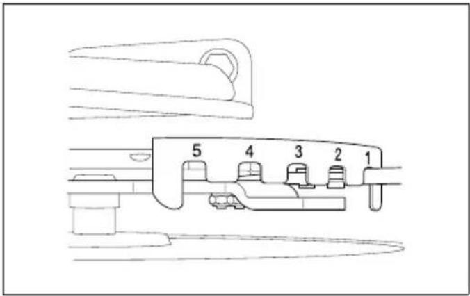
6. ADJUSTMENT OF CUTTING HEIGHT
Apply outward pressure to disengage lever from rack. Move lever forward or back to adjust height.
The height (the blade to the ground) can be adjusted from 25 mm (1 position: the lowest position) to 70 mm (5 position: the highest position), 5 height positions. (Fig. 3A, Fig. 3B).
Stop mower and disconnect spark plug cable before changing mower cutting height.

WARNING: Make this adjustment only when the stopped.
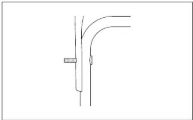
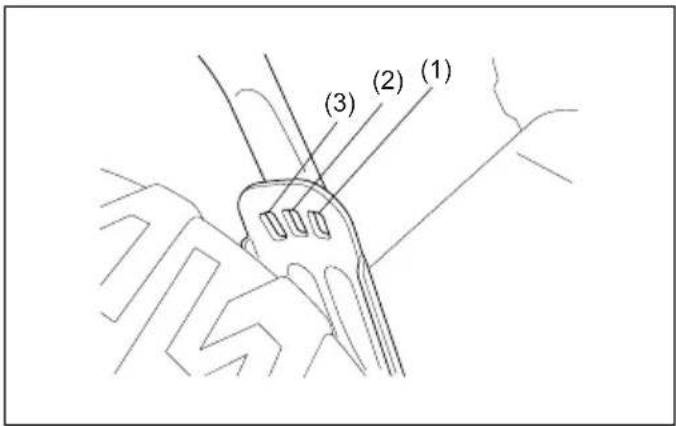
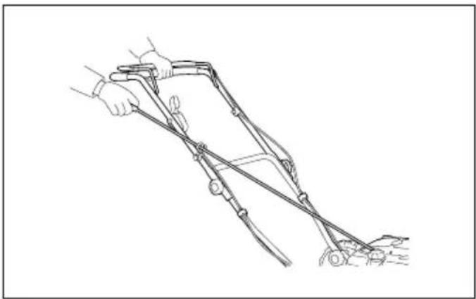
7. ADJUSTMENT FOR AN APPROPRIATE HEIGHT (Fig. 4A, Fig. 4B)
- Back out the locking knobs which fixed the lower handle, refer to Fig. 4A.
- Refer to Fig. 4B move the lower handle up and down, adjust it to the proper height.
There are 3 adjusting heights to be chosen on this type of lawn mower; at position 1 height is highest., at position 3 height is the lowest.
- Adjusting to the proper height, then fix the lower handle by the locking knobs.

WARNING: The left side and right side of lower
handle must adjust to the same height.
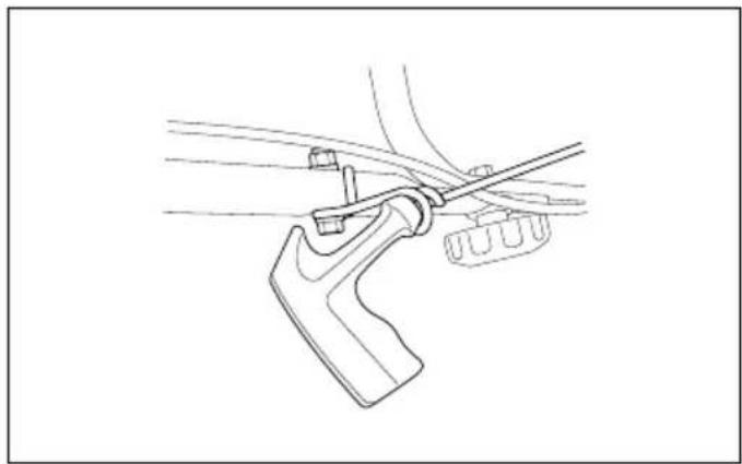
8. STARTER HANDLE (Fig. 5)
Move the starter handle from the engine to the rope guide.
9. "2 IN 1"
9-1 RESETTING FOR SIDE DISCHARGE MOWING
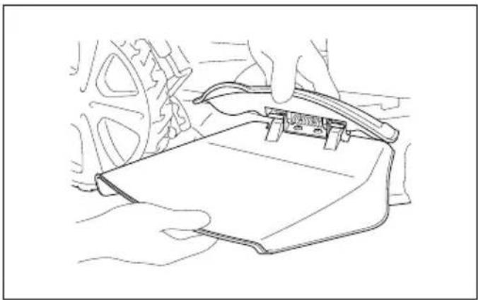
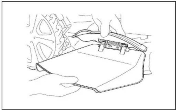
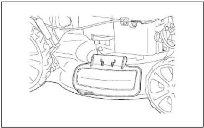
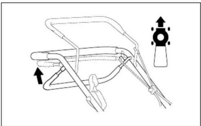
- Lift sideward flap for side discharge. (Fig. 6A)
- Mount the discharge guide for side discharge on the support pin of the sideward flap. (Fig. 6A, Fig. 6B)
- Lower the sideward flap- the flap lies on the discharge channel. (Fig. 6C)

Only when motor and cutter are at standstill!
9-2 MULCHING MOWER
What is mulching?
When mulching, the grass is cut in one working step, then finely chopped and returned to the grass strip as natural fertilizer.
Hints for mulch-mowing:
- Regular cut-back by max. 2 cm form 6 cm to 4 cm grass height.
- Use a sharp cutting knife
- Do not mow wet grass
- Set max. motor speed
- Only move at working pace
- Regularly clean mulching wedge, housing inner side and mowing blade

WARNING: Only with a stopped motor and
standstill cutter.
-
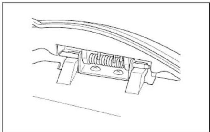
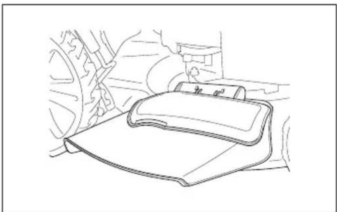
Raise the sideward flap and remove the discharge channel. (Fig. 7A, Fig. 7B)
-
The sideward flap automatically closes the discharge opening on the housing by mean of spring force.
- Regularly clean the sideward flap and discharge opening form grass rest and stuck dirt.
10. OPERATING INSTRUCTIONS
10-1 BEFORE STARTING
Service the engine with gasoline and oil as instructed in the separate engine manual packed in your mower. Read instructions carefully.

WARNING: Petrol is highly flammable.
Store fuel in containers specifically designed for this purpose.
Refuel outdoors only, before starting the engine and do not smoke while refueling or handling fuel.
Never remove the cap of the fuel tank or add petrol while the engine is running or when the engine is hot.
If petrol is spilled, do not attempt to start the engine but move the machine away from the area of spillage and avoid creating any source of ignition until petrol vapors have dissipated.
Replace all fuel tanks and container caps securely. Before tipping the lawn mower to maintain the blade or drain oil, remove fuel from tank.

WARNING: Never fill fuel tank indoors, with
engine running or until the engine has been allowed to cool for at least 15 minutes after running.
10-2 TO START ENGINE AND ENGAGE BLADE
- The unit is equipped with a rubber boot over the end of the spark plug, make certain the metal loop on the end of the spark plug wire (inside the rubber boot) is fastened securely over the metal tip on the spark plug.
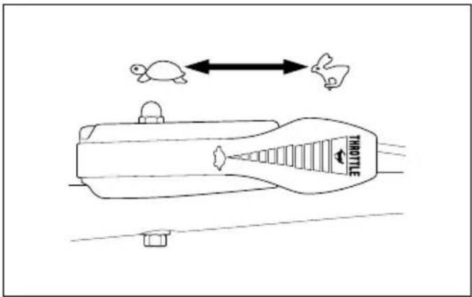
2.1. For PLM5121:
When starting cool or warm engine, turn throttle choke lever at anywhere between “ ” position to “ ” position. When operating, turn throttle choke lever to “ ” position. (Fig. 8B)
2.2. For PLM5120:
When starting cool, press the primer bulb 3-5 times before starting the engine, turn throttle choke lever to “” position.
When starting warm engine and operating, turn throttle choke lever to “*” position. (Fig. 8A, Fig. 8B)
-
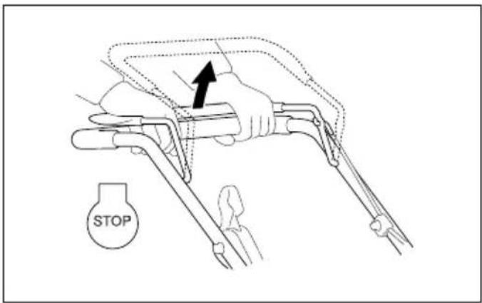
Standing behind the unit grasp the brake control handle and hold it against the upper handle as shown in Fig. 8C.
-
Grasp the starter handle as shown Fig. 8C and pull up rapidly. Return it slowly to the rope guide bolt after engine starts.
Release the brake control handle to stop the engine and blade. (Fig. 8D)

Start the engine carefully according to ons and with feet well away from the blade.

Do not tilt the lawn mower when starting the Start the mower on a level surface, free of high obstacles.

Keep hands and feet away from the rotating
to not start the engine when standing in front of the
ge opening.
During operation, tightly hold the brake handle with both hands.

NOTE: During operation, when the brake handle used, the engine will stop and thus stopping the power from operating.
10-4 TO STOP ENGINE

CAUTION: The blade continues to rotate for a bonds after the engine is shut off.
- Release the brake control handle to stop the engine and blade.
- Disconnect and ground the spark plug wire as instructed in the separate engine manual to prevent accidental starting while equipment is unattended.
10-5 CONNECTION FOR AUTO MOVE
For PLM5121
Grip the Self-drive control handle, the lawn mower will move forward automatically with about 3.6 km/h (Fig. 9), release the self-drive handle, the lawn mower will stop move.

CAUTION: Your mower is designed to cut normal ial grass of a height no more than 250 mm.
Do not attempt to mow through unusually tall dry or wet grass (e.g., pasture) or piles of dry leaves. Debris may build up on the mower deck or contact the engine exhaust presenting a potential fire hazard.
10-6 FOR THE BEST RESULTS WHEN MOWING
Clear lawn of debris. Be sure that the lawn is clear of stones, sticks, wire or other foreign objects which could be accidentally thrown out by the mower in any direction and cause serious personal injury to the operator and others as well as damage to property and surrounding objects. Do not cut wet grass. For effective mowing do not cut wet grass because it tends to stick to the underside of the deck preventing proper mowing of the grass clippings. Cut no more than 1/3 the length of the grass. The recommended cut for mowing is 1/3 the length of the grass. Ground speed will need to be adjusted so the clippings can be dispersed evenly into the lawn. For
especially heavy cutting in thick grass it may be necessary to use one of the slowest speeds in order to get a clean well mowed cut. When mowing long grass you may have to cut the lawn in two passes, lowering the blade another 1/3 of the length for the second cut and perhaps cutting in a different pattern than was used the first time. Overlapping the cut a little on each pass will also help to clean up any stray clippings left on the lawn. The mower should always be operated at full throttle to get the best cut and allow it to do the most effective job of mowing. Clean underside of deck. Be certain to clean the underside of the cutting deck after each use to avoid a build-up of grass, which would prevent proper mulching. Mowing leaves. The mowing of leaves can also be beneficial to your lawn. When mowing leaves make sure they are dry and are not laying too thick on the lawn. Do not wait for all the leaves to be off the trees before you mow.

WARNING: If you strike a foreign object, stop the
engine. Remove wire from spark plug, thoroughly inspect the mower for any damage and repair the damage before restarting and operating the mower. Extensive vibration of the mower during operation is an indication of damage. The unit should be promptly inspected and repaired.
10-7 DECK
The underside of the mower deck should be cleaned after each use to prevent a buildup of grass clippings, leaves, dirt or other matter. If this debris is allowed to accumulate, it will invite rust and corrosion, and may prevent proper mulching. The deck may be cleaned by tilting the mower and scraping clean with a suitable tool (make certain the spark plug wire is disconnected).
11. MAINTENANCE INSTRUCTIONS
SPARK PLUG
Use only original replacement spark plug. For best results, replace the spark plug every 100 hours of use.
12. LUBRICATION INSTRUCIONS

CAUTION: DISCONNECT SPARK PLUG
BEFORE SERVICING.
- WHEELS-Lubricate the ball bearings in each wheel at least once a season with a light oil.
- ENGINE-Follow engine manual for lubrication instructions.
- BLADE CONTROL-Lubricate the pivot points on the blade control handle and the brake cable at least once a season with light oil. The blade control must operate freely in both directions.
13. CLEANING

CAUTION: Do not hose engine. Water can
damage engine or contaminate the fuel system.
- Wipe deck with dry cloth.
- Hose under deck by tilting the mower so that the spark plug is up.
13-1 ENGINE AIR CLEANER

CAUTION: Do not allow dirt or dust to clog the air
filter foam element. The engine air cleaner element must be serviced (cleaned) after 25 hours normal mowing. The foam element must be serviced regularly if the mower is used in dry dusty conditions. (Refer to ENGINE OWNER'S MANUAL)
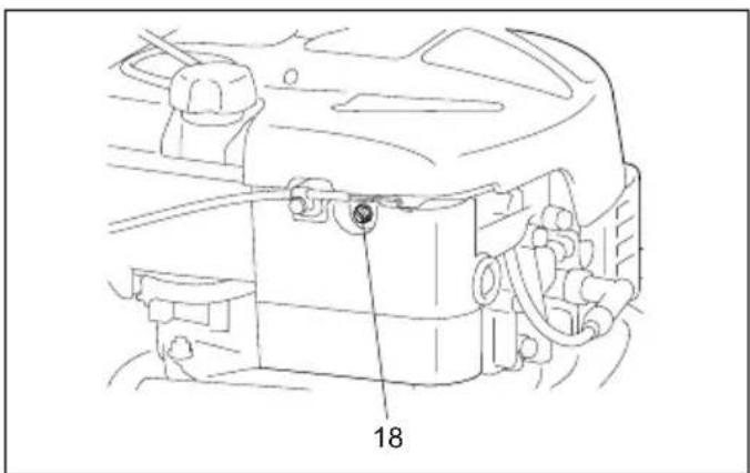
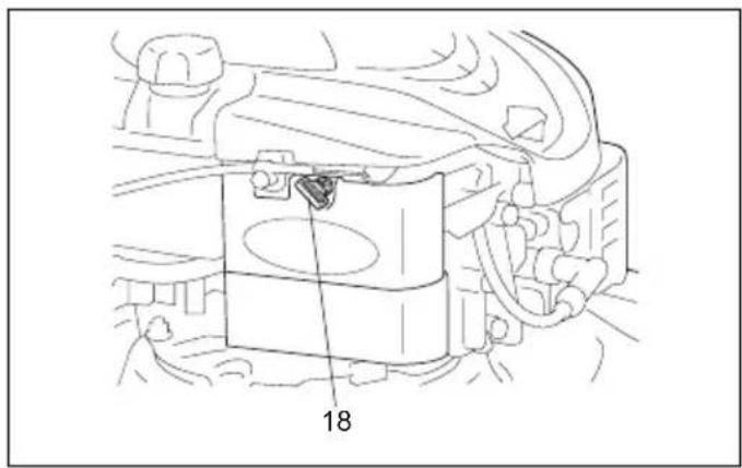
To CLEAN AIR FILTER
- Remove screw. (Fig. 10A, Fig. 10B)
- Remove cover.
- Wash filter element in soap water. DO NOT USE GASOLINE!
- Air dry filter element.
- Place a few drops of SAE30 oil on the foam filter and squeeze tightly to remove any excess oil.
- Reinstall filter.

NOTE: Replace filter if frayed, torn, damaged or
unable to be cleaned.
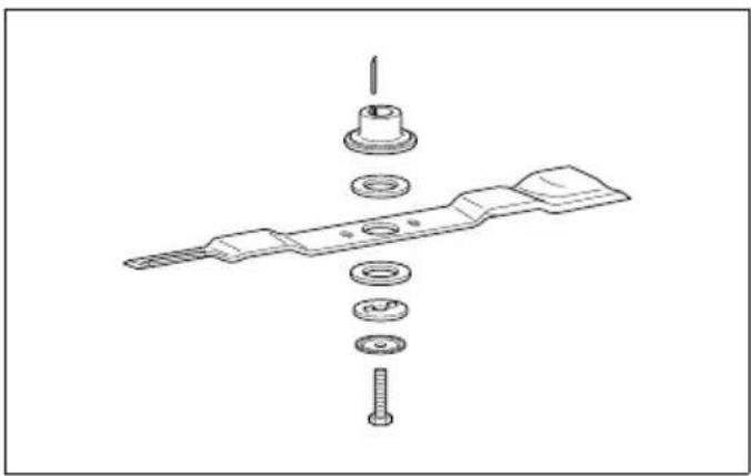
13-2 CUTTING BLADE

CAUTION: Be sure to disconnect and ground the
spark plug wire before working on the cutting blade to prevent accidental engine starting. Protect hands by using heavy gloves or a rag to grasp the cutting blades. Tip mower as specified in separate engine manual. Remove the hex bolt and washer which hold the blade and blade adapter to the engine crankshaft. Remove the blade and adapter from the crankshaft.

WARNING: Periodically inspect the blade
adapter for cracks, especially if you strike a foreign object. Replace when necessary.
For best results your blade should be sharp. The blade may be retargeted by removing it and either grinding or filing the cutting edge keeping as close to the original bevel as possible. It is extremely important that each cutting edge receives an equal amount of grinding to prevent an unbalanced blade. Improper blade balance will result in excessive vibration causing eventual damage to the engine and mower. Be sure to carefully balance blade after sharpening. The blade can be tested for balance by balancing it on a round shaft screwdriver. Remove metal from the heavy side until it balances evenly. Before reassembling the blade and the blade adapter to the unit, lubricate the engine crankshaft and the inner surface of the blade adapter with light oil. Install the blade adapter on the engine crankshaft. Refer to Fig. 11. Place the blade with the part number facing away from the adapter. Align the washer over the blade and insert the hex bolt. Tighten the hex bolt to the torque listed below:
13-3 BLADE MOUNTING TORQUE
Center Bolt 40Nm-50Nm, to insure safe operation of your unit. ALL nuts and bolts must be checked periodically for correct tightness.
After prolonged use, especially in sandy soil conditions, the blade will become worn and lose some of the original shape. Cutting efficiently will be reduced and the blade should be replaced. Replace with an approved factory replacement blade only. Possible damage resulting from blade unbalance condition is not the responsibility of the manufacturer.
When you change the blade, you must use the original type marked on the blade (MAKITA 263001826) (for order the blade, pls. contact your local dealer or call our company).

WARNING: Do not touch rotating blade.
13-4 ENGINE
Refer to the separate engine manual for engine maintenance instructions.
Maintain engine oil as instructed in the separate engine manual packed with your unit. Read and follow instructions carefully.
Service air cleaner as per separate engine manual under normal conditions.
Clean every few hours under extremely dusty conditions.
Poor engine performance and flooding usually indicates that the air cleaner should be serviced.
To service the air cleaner, refer to the separate engine manual packed with your unit.
The spark plug should be cleaned and the gap reset once a season. Spark plug replacement is recommended at the start of each mowing season; check engine manual for correct plug type and gap specifications.
Clean the engine regularly with a cloth or brush. Keep the cooling system (blower housing area) clean to permit proper air circulation which is essential to engine performance and life. Be certain to remove all grass, dirt and combustible debris from muffler area.
14. STORAGE INSTRUCTIONS (OFF SEASON)
The following steps should be taken to prepare lawn mower for storage.
- Empty the tank after the last mowing of the season.
a) Empty the petrol tank with a suction pump.

CAUTION: Do not drain the petrol in closed rooms, in close proximity of open fire, etc. Do not smoke! Petrol fumes can cause explosion or fire.
b) Start the engine and let it run until it has used up all remaining petrol and stalls.
c) Remove the spark plug. Use an oilcan to fill approx. 20 ml oil into the combustion chamber. Operate the starter to evenly distribute the oil in the combustion chamber. Replace the spark plug.
-
Clean and grease the lawn mower carefully as described above under "Lubrication".
-
Slightly grease the cutter to avoid corrosion.
-
Store the lawn mower in a dry, clean and frost-protected place, out of reach of unauthorized persons.

CAUTION: The engine must have completely down before storing the lawn mower.

NOTE:
- When storing any type of power equipment in an unventilated or material storage shed, care should be taken to rust-proof the equipment. Using a light oil or silicone, coat the equipment, especially cables and all moving parts.
- Be careful not to bend or kink cables.
- If the starter rope becomes disconnected from rope guide on handle, disconnect and ground the spark plug wire, Depress the blade control handle and pull the starter rope out from engine slowly. Slip the starter rope into the rope guide bolt on handle.
Transport
Turn the engine off. Ensure not to bend or damage the cutter when pushing the lawn mower over obstacles.
15. TROUBLES SHOOTING
| PROBLEM PROBA BLE CAUSE CORRECTIVE ACTION |
| Engine does not start. Throttle chock not in the correct position for the prevailing conditions. | Move throttle chock to correct position. |
| Fuel tank is empty. Fill tank with fuel: refer to ENGINE OWNER'S MANUAL. |
| Air cleaner element is dirty. Clean air cleaner element: refer to ENGINE OWNER'S MANUAL. |
| Spark plug loose. Tighten spark plug to 25-30 Nm. |
| Spark plug wire loose or disconnected from plug. Install spark plug wire on spark plug. |
| Spark plug gap is incorrect. Set gap between electrodes at 0.7 to 0.8 mm. |
| Spark plug is defective. Install new, correctly gapped plug: refer to ENGINE OWNER'S MANUAL. |
| Carburetor is flooded with fuel. Remove air cleaner element and pull starter rope continuously until carburetor clears itself and install air cleaner element. |
| Faulty ignition module. Contact the service agent. |
| Engine difficult to start or loses power. | Dirt, water, or stale fuel tank. | Drain fuel and clean tank. Fill tank with clean, fresh fuel. |
| Vent hole in fuel tank cap is plugged. | Clean or replace fuel tank cap. |
| Air cleaner element is dirty. Clean air cleaner element. |
| Engine operates erratically. | Spark plug is defective. Install new, correctly gapped plug: refer to ENGINE OWNER'S MANUAL. |
| Spark plug gap is incorrect. Set gap between electrodes at 0.7 to 0.8 mm. |
| Air cleaner element is dirty. Clean air cleaner element: refer to ENGINE OWNER'S MANUAL. |
| Engine idles poorly. Air cleaner element is dirty. Clean air cleaner element: refer to ENGINE OWNER'S MANUAL. |
|
|
|
| Engine skips at high speed. | Gap between electrodes of spark plug is too close. | Set gap between electrodes at 0.7 to 0.8 mm. |
| Engine overheats. | Cooling air flow is restricted. | Remover any debris from slots in shroud, blower housing, air passages. |
| Incorrect spark plug. | Install RJ19LMC spark plug and cooling fins on engine. |
| Mower vibrates abnormally. | Cutting assembly is loose. | Tighten blade. |
| Cutting assembly is unbalanced. | Balance blade. |
16. WARRANTY
This product is warranted in accordance with legal regulations for a 12 months period effective from the date of purchase by the first user.
This warranty covers all material or production failures, it does not include defects from normal wear & tear parts, such as bearings, brushes, cables, plugs or accessories like drills, drill bits, saw blades etc.; damage or defects resulting from abuse, accidents or alterations; nor the costs for transport.
We reserve the right to reject any claim where the purchase cannot be verified or when it is clear that the product was not maintained properly. (Clean ventilation slots, carbon brushes serviced regularly.)
Your purchase ticket must be kept as proof for date of purchase.
Your un-dismantled tool must be returned to your dealer in an acceptably clean state, in its original blow molded case if applicable to unit, accompanied by your proof of purchase.
17. ENVIRONMENT
Should your machine need replacement after extended use, do not put it in the domestic waste but dispose of it in an environmentally safe way.
(For European countries only)
We Makita Corporation as the responsible
manufacturer declare that the following Makita machine(s):
Designation of Machine: Petrol Lawn Mower
Model No./ Type: PLM5120, PLM5121
Specifications: See "4. TECHNICAL DATA"
are of series production and
Conforms to the following European Directives:
2004/108/EC, 2006/42/EC, 2000/14/EC&2005/88/EC
And are manufactured in accordance with the following standards or standardised documents:
EN ISO 14982, EN836
The technical documentation is kept by our authorized representatives in Europe who is:
Makita International Europe Ltd.
Michigan Drive, Tongwell,
Milton Keynes, Bucks MK15 8JD, England
The conformity assessment procedure required by
Directive 2000/14/EC was in Accordance with Annex V.
Notified Body:
Measured Sound Power level: 92.3 dB (A)
Guaranteed Sound Power level: 98 dB (A)
Model: PLM5121
Measured Sound Power level: 92.4 dB (A)
Guaranteed Sound Power level: 98 dB (A)
30.11.2011

Tomoyasu Kato
Director
Makita Corporation
3-11-8, Sumiyoshi-cho,
Anjo, Aichi, JAPAN
Michigan Drive, Tongwell,
Milton Keynes, Bucks MK15 8JD, Angleterre
3-11-8, Sumiyoshi-cho,
Anjo, Aichi, JAPAN
1. SYMBOLE AM PRODUKT

5-1 MONTIEREN DES KLAPPBAREN GRIFFS
2004/108/EG, 2006/42/EG,
2000/14/EG&2005/88/EG
Michigan Drive, Tongwell,
Milton Keynes, Bucks MK15 8JD, England
3-11-8, Sumiyoshi-cho,
Anjo, Aichi, JAPAN
Michigan Drive, Tongwell,
Milton Keynes, Bucks MK15 8JD, Inghilterra
3-11-8, Sumiyoshi-cho,
Anjo, Aichi, JAPAN
Let op: Motor is heet.
2. ALGEMENE VEILIGHEIDSVOORSCHRIFTEN
5-1 DE INKLAPBARE HANDGREEP MONTEREN
WAARSCHUWING: Benzine is bijzonder
brandbaar.
2004/108/EC, 2006/42/EC,
2000/14/EC en 2005/88/EC
Michigan Drive, Tongwell,
Milton Keynes, Bucks MK15 8JD, Engeland
3-11-8, Sumiyoshi-cho,
Anjo, Aichi, JAPAN
2004/108/CE, 2006/42/CE,
2000/14/CE y 2005/88/CE
Michigan Drive, Tongwell,
Milton Keynes, Bucks MK15 8JD, Inglaterra
3-11-8, Sumiyoshi-cho,
Anjo, Aichi, JAPAN
Michigan Drive, Tongwell,
Milton Keynes, Bucks MK15 8JD, Inglaterra
3-11-8, Sumiyoshi-cho,
Anjo, Aichi, JAPAN
13-3 KNIVMONTERINGSMOMENT
2004/108/EF, 2006/42/EF, 2000/14/EF&2005/88/EF
Og er produceret i overensstemmelse med følgende
standarder eller standardiserede dokumenter:
EN ISO 14982, EN836
Michigan Drive, Tongwell,
Milton Keynes, Bucks MK15 8JD, England
3-11-8, Sumiyoshi-cho,
Anjo, Aichi, JAPAN
2004/108/EK, 2006/42/EK, 2000/14/EK&2005/88/EK
Michigan Drive, Tongwell,
Milton Keynes, Bucks MK15 8JD, England
3-11-8, Sumiyoshi-cho,
Anjo, Aichi, JAPAN
TÜRKÇE (Orijinal talimatlar)
Genel görünüm
Michigan Drive, Tongwell,
3-11-8, Sumiyoshi-cho,
Anjo, Aichi, JAPAN
SVENSKA (Originalanvisningar)
5-1 MONTERA DET FÄLLBARA HANDTAGET
10-2 STARTA MOTORN OCH KOPPLA IN KNIVEN
Michigan Drive, Tongwell,
Milton Keynes, Bucks MK15 8JD, England
1. SYMBOLENE PÅ PRODUKTET

9-1 INNSTILLING FOR KLIPPING MED SIDEUTL∅P
FORSIKTIG: KOPLE FRA TENNPLUGGEN
F∅R VEDLIKEHOLD.
- HJUL - Smør kulelagrene i hvert hjul med en lett olje minst en gang i sesongen.
- MOTOR - Følg angivelsene i motorens bruksanvisning for smøring.
- BLADKONTROLL - Smør leddpunktene på bladets kontrollhåndtak og bremsekabelen med en lett olje minst en gang i sesongen. Bladkontrollen skal kunne bevege seg fritt i begge retninger.
13. RENGJ∅RING

2004/108/EF, 2006/42/EF,
Michigan Drive, Tongwell,
Milton Keynes, Bucks MK15 8JD, England
3-11-8, Sumiyoshi-cho,
Anjo, Aichi, JAPAN
Michigan Drive, Tongwell,
Milton Keynes, Bucks MK15 8JD, England
3-11-8, Sumiyoshi-cho,
Anjo, Aichi, JAPAN
2004/108/EK, 2006/42/EK,
2000/14/EK un 2005/88/EK
Michigan Drive, Tongwell,
Milton Keynes, Bucks MK15 8JD, Anglija
3-11-8, Sumiyoshi-cho,
Anjo, Aichi, JAPAN
LIETUVIŲ KALBA (Originali instrukcija)
Bendrasis aprašymas
2004/108/EB, 2006/42/EB,
2000/14/EB ir 2005/88/EB
Michigan Drive, Tongwell,
Milton Keynes, Bucks MK15 8JD, England (Anglija)
3-11-8, Sumiyoshi-cho,
Anjo, Aichi, JAPAN
2.1. Ainult PLM5121:
Michigan Drive, Tongwell,
Milton Keynes, Bucks MK15 8JD, Inglismaa
3-11-8, Sumiyoshi-cho,
Anjo, Aichi, JAPAN
Makita International Europe Ltd.
Michigan Drive, Tongwell,
Milton Keynes, Bucks MK15 8JD, England
Michigan Drive, Tongwell,
Milton Keynes, Bucks MK15 8JD, Англія
3-11-8, Sumiyoshi-cho,
Anjo, Aichi, JAPAN
2004/108/WE, 2006/42/WE,
Michigan Drive, Tongwell,
Milton Keynes, Bucks MK15 8JD, Wielka Brytania
3-11-8, Sumiyoshi-cho,
Anjo, Aichi, JAPAN
2004/108/CE, 2006/42/CE,
Michigan Drive, Tongwell,
Milton Keynes, Bucks MK15 8JD, Anglia
3-11-8, Sumiyoshi-cho,
Anjo, Aichi, JAPAN
2004/108/EK, 2006/42/EK,
Michigan Drive, Tongwell,
Milton Keynes, Bucks MK15 8JD, Anglia
3-11-8, Sumiyoshi-cho,
Anjo, Aichi, JAPAN
2004/108/ES, 2006/42/ES,
2000/14/ES a 2005/88/ES
Michigan Drive, Tongwell,
Milton Keynes, Bucks MK15 8JD, Anglicko
3-11-8, Sumiyoshi-cho,
Anjo, Aichi, JAPAN
5-1 MONTÁŽ SKLÁPĚCÍHO DRŽADLA
2004/108/ES, 2006/42/ES,
2000/14/ES a 2005/88/ES
Michigan Drive, Tongwell,
Milton Keynes, Bucks MK15 8JD, England
3-11-8, Sumiyoshi-cho,
Anjo, Aichi, JAPAN
Makita Corporation
Anjo, Aichi, Japan
PLM5120-23L-1011
ALA
www.makita.com

