
DMR188 - Surveillance Camera Monacor - Free user manual and instructions
Find the device manual for free DMR188 Monacor in PDF.
| Product type | 8-channel digital video recorder |
| Brand | Monacor |
| Model | DMR188 |
| Video standard | PAL / NTSC selectable |
| Video inputs | 8 × BNC |
| Video outputs | 2 × BNC, 1 × VGA |
| Audio inputs | 1 × RCA |
| Audio outputs | 1 × RCA |
| Recording resolution | CIF (352 × 288 PAL / 352 × 240 NTSC) |
| Video compression | H.264 |
| Max. recording rate | 200 fps (PAL) / 240 fps (NTSC) |
| Hard drive | Internal SATA (max 1 TB, not included) |
| Alarm inputs | 8, NO/NC contacts selectable |
| Alarm output | 1 NO contact, max. 24 V / 500 mA |
| PTZ control | Yes, via RS-485, PELCO-P/D protocols |
| Interfaces | 2 × USB 2.0 (mouse, storage), 1 × RJ45 Ethernet |
| Power supply | 12 V DC / 3 A (power adapter included) |
| Power consumption | 0.8 - 1.3 A at 12 V (without hard drive) |
| Dimensions (W × H × D) | 300 × 55 × 225 mm |
| Weight | 3.7 kg |
| Operating temperature | 0 - 40 °C |
| Main functions | Continuous, scheduled, alarm or manual recording; motion detection; remote access via PC (IE/D9-Viewer) or mobile; video export; live display and playback |
| Care and cleaning | Use a dry, soft cloth; do not use chemicals or water. |
| Safety | Do not expose to water splashes; disconnect before maintenance; repairs by qualified technician. |
| Spare parts and repairability | SATA hard drive (max 1 TB) replaceable; power adapter and remote control included; repair by professional. |
Frequently Asked Questions - DMR188 Monacor
User questions about DMR188 Monacor
0 question about this device. Answer the ones you know or ask your own.
Ask a new question about this device
Download the instructions for your Surveillance Camera in PDF format for free! Find your manual DMR188 - Monacor and take your electronic device back in hand. On this page are published all the documents necessary for the use of your device. DMR188 by Monacor.
USER MANUAL DMR188 Monacor
Before switching on ...
We wish you much pleasure with your new MONACOR unit. Please read these operating instructions carefully prior to operating the unit. Thus, you will get to know all functions of the unit, operating errors will be prevented, and yourself and the unit will be protected against any damage caused by improper use. Please keep the operating instructions for later use.
The English text starts on page 22.
35Audio Channel Setting
NO Kontaktart Schlieber (normally open)
NC Kontaktart Offner (normally closed)
Anzeige: 2x^ ,4x^ ,8x^ ,16x^
SLOW zur Wiedergabe in Zeitlupe
Access Control Address)
1 Operating Elements and Connections 22
1.1 Front side of the recorder 22
1.2 Rear side of the recorder 22
1.3 Infrared remote control 23
2 Safety Notes 23
3 Applications 23
4 Installing a Hard Disk 23
5 Connecting Units 23
5.1 Video connections 23
5.2 Audio connections 23
5.3 Alarm and control connections 24
5.3.1 Alarm inputs 24
5.3.2 Alarm output 24
5.3.3 Camera remote control (PTZ) 24
5.4 Mouse 24
5.5 USB storage medium 24
5.6 Computer network (LAN) 24
5.7 Mains connection 24
5.8 Inserting batteries into the remote control . 24
6 Operation 24
6.1 Activating the OSD menu 24
6.2 Basic settings 25
6.2.1 Changing the menu language 25
6.2.2 Video settings 25
6.2.3 Camera names 25
6.2.4 Date and time 26
6.2.5 Correcting image properties 26
7 Live surveillance 27
7.1 Display options 27
7.2 Configuring the sequence function 27
7.3Activating/deactivatingthe sequence function 27
8 Recording 27
8.1 General settings for recording 27
8.1.1 Configuring/deleting the hard disk 28
8.2 Recording control 28
8.2.1 Permanent recording 28
8.2.2 Manual start of recording 28
8.2.3 Time-controlled recording 28
8.2.4 Alarm-controlled recording 28
8.2.5 Insertions during recording 28
8.2.6 Storage according to type of recording . 28
9 Replay 29
9.1 Exporting video files 29
9.1.1 Formatting the USB storage medium 30
9.2 Replay of recordings with the program PLAYBACK 30
9.2.1 Opening video files 30
9.2.1.1 Opening a single video file 30
9.2.1.2 Opening several files at the same time or searching for a video file 30
9.2.1.3 Opening several independent players . 30
9.2.2Replaying video recordings 30
9.2.3 Processing video files 30
9.2.3.1 Storing snapshots 30
9.2.3.2 Extracting a passage 30
9.2.3.3 Storing a video file in AVI format . . . 31
9.2.3.4 Deleting video files 31
9.2.4 Changing settings 31
9.2.4.1 Selecting camera channels 31
9.2.4.2 Selecting audio replay 31
9.2.4.3 Defining window arrangements 31
10 Alarm Functions 32
10.1 Alarm configuration 32
10.2 Notification by e-mail 32
10.3 Motion detection 32
11.1 Configuring the control parameters 33
11.2 Controlling a camera 33
12.1 Configuring the password protection 34
12.2 Activating the password protection 34
13 System Maintenance 34
13.1 Indicating system information 35
14.1 Setting up a network connection 35
14.2 Remote control via the programs Windows Internet Explorer or 9D-VIEWER 35
14.2.1.1 Storing snapshots 36
14.2.1.2 Recording video sequences 36
14.2.1.3 Camera control (PTZ CONTROL) 36
14.2.2 View "REPLAY" 36
14.2.2.1 Replay control 37
14.2.2.2 Converting video files 37
14.2.3.1 SETUP/RECORD 37
14.2.3.2 SETUP/ALARM 37
14.2.3.3 SETUP/PTZ 38
14.2.3.4 SETUP/NETWORK 38
14.2.3.5 SETUP/SETTING 38
14.2.3.6 SETUP/HOST INFO 38
14.2.4 View "LOGOUT" 38
14.3 Remote access via a mobile phone 39
15 Specifications 39
11 Camera remote control (PTZ) 33
11.3 Configuring the CRUISE function 33
11.4Activating/deactivating the CRUISE function 33
12 Password Protection 34
14 Remote Access via Computer Network . 35
14.2.1 View "LIVE" 36
14.2.3 View "SETUP" 37
1 Operating Elements and Connections
1.1 Front side of the recorder
1 Power switch
2 Power LED PWR
3 Infrared receiver for the remote control; direct the remote control towards this sensor
4 LED HDD; will flash when reading from the hard disk or writing on the hard disk
5DMR-180/DMR-184: buttons 日 ,and to indicate the corresponding channel (CH 1, CH 2, CH 3 or CH 4) as a full image
DMR-188:
buttons 十 and to select a channel (CH 1 to CH 8) for full image display
button SEARCH to directly activate the submenu for searching for particular video recordings
button MUTE to mute the sound when replaying
6DMR-180/DMR-184
button to change from full image display of a channel to quadrant display of all channels DMR-188
button to change from full image display of a channel to display of several channels; each time the button is pressed, the view is switched between quadrant display of the channels CH 1 to CH 4, CH 5 to CH 8 and simultaneous display of all eight channels
7 Button MENU/ESC to activate and deactivate the main menu, to deactivate a submenu or an input field
8 Buttons and to select a menu item, an input field, a list entry, an inserting position or a button
9 Button SEL/EDIT to activate the menu list or a submenu and to confirm a selection or input
0 Button REW for fast rewind when replaying a video recording (2-fold, 4-fold or 9-fold replay speed); in the menu: to select a menu item, an input field, a list entry, an inserting position or a button
1 Button PAUSE to interrupt the replay (PAUSE) and to continue in frames (FRAME) each time the button is pressed; to activate/deactivate the sequence function
2 Button PLAY to start the replay of a video recording and to continue the replay after an interruption
3 Button FWD for fast forward when replaying a video recording (2-fold, 4-fold or 9-fold replay speed); in the menu: to select a menu item, an input field, a list entry, an inserting position or a button
4 Button STOP to stop the replay or to stop a recording started manually
5 Button REC to start a recording manually (for this purpose, the channels to be recorded must be released in the setting menu chapter 8.1)
6 Button PTZ to activate the menu list (where the menu item PTZ for controlling the camera will also be selected)
.2 Rear side of the recorder
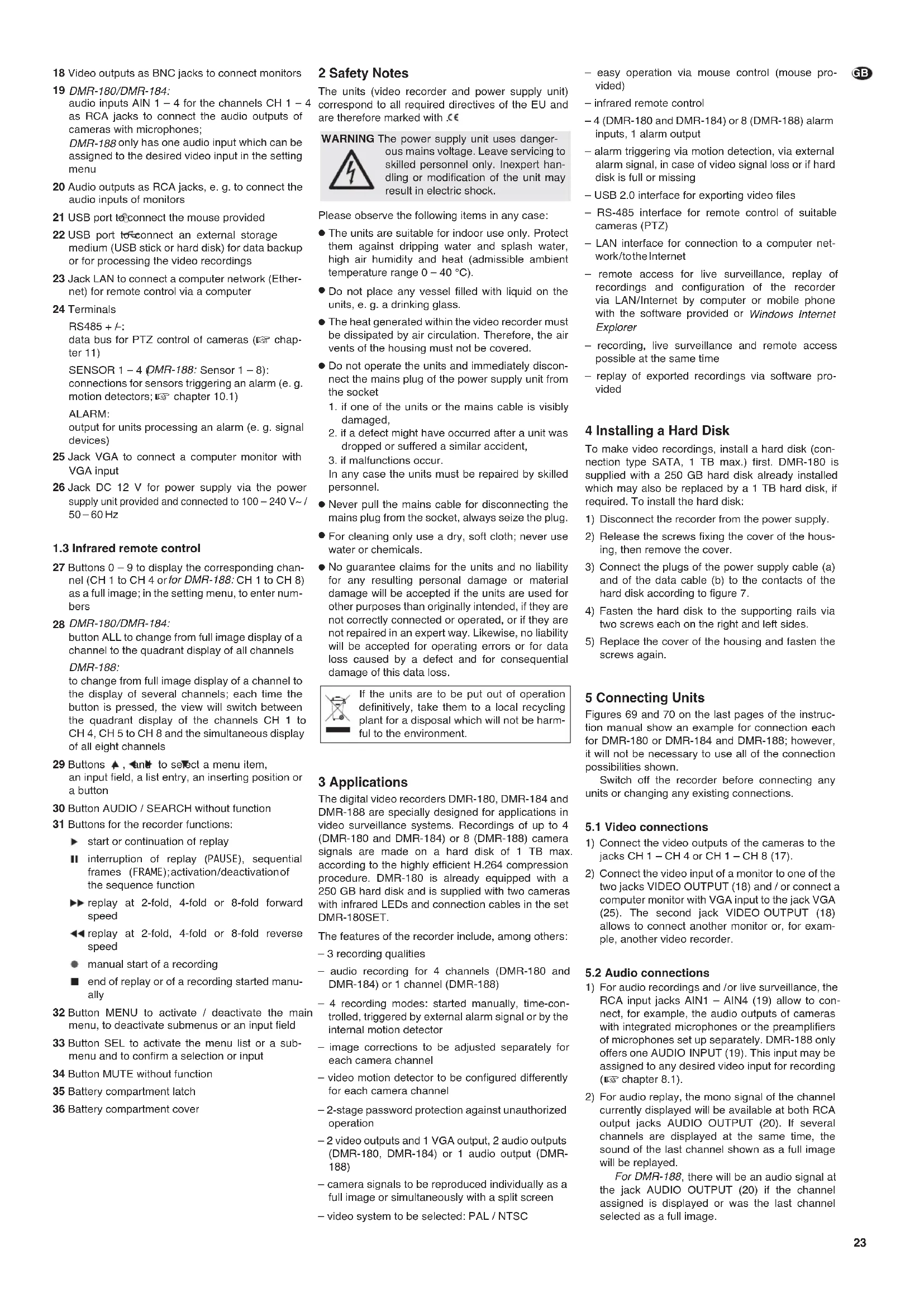
17 Video inputs as BNC jacks to connect the cameras
18 Video outputs as BNC jacks to connect monitors
19 DMR-180/DMR-184: audio inputs AIN 1 - 4 for the channels CH 1 - as RCA jacks to connect the audio outputs of cameras with microphones; DMR-188 only has one audio input which can be assigned to the desired video input in the setting menu
20 Audio outputs as RCA jacks, e. g. to connect the audio inputs of monitors
21 USB port to connect the mouse provided
22 USB port to connect an external storage medium (USB stick or hard disk) for data backup or for processing the video recordings
23 Jack LAN to connect a computer network (Ethernet) for remote control via a computer
24 Terminals RS485+data bus for PTZ control of cameras (13 chap-ter 11)
SENSOR 1-4 DMR-188: Sensor 1-8) connections for sensors triggering an alarm (e.g. motion detectors; chapter 10.1)
ALARM:
output for units processing an alarm (e.g. signal devices)
25 Jack VGA to connect a computer monitor with VGA input
26 Jack DC 12 V for power supply via the power supply unit provided and connected to 100 - 240V / 50 - 60Hz
1.3 Infrared remote control
27 Buttons 0 - 9 to display the corresponding channel (CH 1 to CH 4 or for DMR-188:CH 1 to CH 8) as a full image; in the setting menu, to enter numbers
28 DMR-180/DMR-184: button ALL to change from full image display of a channel to the quadrant display of all channels
DMR-188: to change from full image display of a channel to the display of several channels; each time the button is pressed, the view will switch between the quadrant display of the channels CH 1 to CH 4, CH 5 to CH 8 and the simultaneous display of all eight channels
29 Buttons 喜 , and to select a menu item,
an input field, a list entry, an inserting position or a button
30 Button AUDIO / SEARCH without function
31 Buttons for the recorder functions:
start or continuation of replay
II interruption of replay (PAUSE), sequential frames (FRAME); activation/deactivation of the sequence function
replay at 2-fold, 4-fold or 8-fold forward speed
replay at 2-fold, 4-fold or 8-fold reverse speed
manual start of a recording
end of replay or of a recording started manually
32 Button MENU to activate / deactivate the main menu, to deactivate submenus or an input field
33 Button SEL to activate the menu list or a submenu and to confirm a selection or input
34 Button MUTE without function
35 Battery compartment latch
36 Battery compartment cover
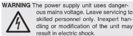
2 Safety Notes
The units (video recorder and power supply unit) correspond to all required directives of the EU and are therefore marked with €
Please observe the following items in any case:
The units are suitable for indoor use only. Protect them against dripping water and splash water, high air humidity and heat (admissible ambient temperature range 0 - 40^ ).
- Do not place any vessel filled with liquid on the units, e. g. a drinking glass.
The heat generated within the video recorder must be dissipated by air circulation. Therefore, the air vents of the housing must not be covered.
- Do not operate the units and immediately disconnect the mains plug of the power supply unit from the socket
- if one of the units or the mains cable is visibly damaged,
-
if a defect might have occurred after a unit was dropped or suffered a similar accident,
-
if malfunctions occur.
In any case the units must be repaired by skilled personnel.
- Never pull the mains cable for disconnecting the mains plug from the socket, always seize the plug.
- For cleaning only use a dry, soft cloth; never use water or chemicals.
No guarantee claims for the units and no liability for any resulting personal damage or material damage will be accepted if the units are used for other purposes than originally intended, if they are not correctly connected or operated, or if they are not repaired in an expert way. Likewise, no liability will be accepted for operating errors or for data loss caused by a defect and for consequential damage of this data loss.

If the units are to be put out of operation definitively, take them to a local recycling plant for a disposal which will not be harmful to the environment.
3 Applications
The digital video recorders DMR-180, DMR-184 and DMR-188 are specially designed for applications in video surveillance systems. Recordings of up to 4 (DMR-180 and DMR-184) or 8 (DMR-188) camera signals are made on a hard disk of 1 TB max. according to the highly efficient H.264 compression procedure. DMR-180 is already equipped with a 250 GB hard disk and is supplied with two cameras with infrared LEDs and connection cables in the set DMR-180SET.
The features of the recorder include, among others:
-3 recording qualities
- audio recording for 4 channels (DMR-180 and DMR-184) or 1 channel (DMR-188)
- 4 recording modes: started manually, time-controlled, triggered by external alarm signal or by the internal motion detector
image corrections to be adjusted separately for each camera channel - video motion detector to be configured differently for each camera channel
-2-stage password protection against unauthorized operation
-2 video outputs and 1 VGA output, 2 audio outputs (DMR-180, DMR-184) or 1 audio output (DMR-188) - camera signals to be reproduced individually as a full image or simultaneously with a split screen
-
video system to be selected: PAL / NTSC
-
easy operation via mouse control (mouse provided)
-infrared remote control
-4 (DMR-180 and DMR-184) or 8 (DMR-188) alarm inputs, 1 alarm output - alarm triggering via motion detection, via external alarm signal, in case of video signal loss or if hard disk is full or missing
- USB 2.0 interface for exporting video files
- RS-485 interface for remote control of suitable cameras (PTZ)
LAN interface for connection to a computer network/totheInternet
remote access for live surveillance, replay of recordings and configuration of the recorder via LAN/Internet by computer or mobile phone with the software provided or Windows Internet Explorer - recording, live surveillance and remote access possible at the same time
- replay of exported recordings via software provided
4 Installing a Hard Disk
To make video recordings, install a hard disk (connection type SATA, 1 TB max.) first. DMR-180 is supplied with a 250 GB hard disk already installed which may also be replaced by a 1 TB hard disk, if required. To install the hard disk:
1) Disconnect the recorder from the power supply.
2) Release the screws fixing the cover of the housing, then remove the cover.
3) Connect the plugs of the power supply cable (a) and of the data cable (b) to the contacts of the hard disk according to figure 7.
4) Fasten the hard disk to the supporting rails via two screws each on the right and left sides.
5) Replace the cover of the housing and fasten the screws again.
5 Connecting Units
Figures 69 and 70 on the last pages of the instruction manual show an example for connection each for DMR-180 or DMR-184 and DMR-188; however, it will not be necessary to use all of the connection possibilities shown.
Switch off the recorder before connecting any units or changing any existing connections.
5.1 Video connections
1) Connect the video outputs of the cameras to the jacks CH 1-CH 4 or CH 1-CH 8 (17).
2) Connect the video input of a monitor to one of the two jacks VIDEO OUTPUT (18) and / or connect a computer monitor with VGA input to the jack VGA (25). The second jack Video OUTPUT (18) allows to connect another monitor or, for example, another video recorder.
5.2 Audio connections
1) For audio recordings and/or live surveillance, the RCA input jacks AIN1 - AIN4 (19) allow to connect, for example, the audio outputs of cameras with integrated microphones or the preamplifiers of microphones set up separately. DMR-188 only offers one AUDIO INPUT (19). This input may be assigned to any desired video input for recording (13 chapter 8.1).
2) For audio replay, the mono signal of the channel currently displayed will be available at both RCA output jacks AUDIO OUTPUT (20). If several channels are displayed at the same time, the sound of the last channel shown as a full image will be replayed.
For DMR-188, there will be an audio signal at the jack AUDIO OUTPUT (20) if the channel assigned is displayed or was the last channel selected as a full image.
It will be possible to reproduce the audio recording or the live sound via a monitor with integrated speaker or via an audio system. For this purpose, connect one of the outputs to the audio input of the monitor or to a line input of the audio system.
5.3 Alarm and control connections
Via the terminal strip (24), the recorder offers various inputs and outputs for control and alarm evaluation.
5.3.1 Alarm inputs
As alarm sensors, use e.g. motion detectors or light barriers equipped with NO (normally open) contacts or NC (normally closed) contacts. Connect the sensors to the following contacts of the terminal strip:
DMR-180 and DMR-184
sensor for channel 1 to contacts 3 and 4 sensor for channel 2 to contacts 5 and 6 sensor for channel 3 to contacts 7 and 8 sensor for channel 4 to contacts 9 and 10
DMR-188
sensor for channel 1 to contacts 3 and 4
sensor for channel 2 to contacts 4 and 5
sensor for channel 3 to contacts 6 and 7
sensor for channel 4 to contacts 7 and 8
sensor for channel 5 to contacts 9 and 10
sensor for channel 6 to contacts 10 and 11
sensor for channel 7 to contacts 12 and 13
sensor for channel 8 to contacts 13 and 14
Adjust the contact type (NO or NC) separately for each channel (e line I/O STATUS in the menu ALARM SETUP, chapter 10.1). Alarm triggering via a normally open contact is factory-set.
5.3.2 Alarm output
As a potential-free alarm output, a relay with normally open contact (with a maximum load of 24V / 500mA ) is available. The alarm output allows to connect, for example, an audible or visible alarm device.
5.3.3 Camera remote control (PTZ)
Via the RS-485 interface, remote control of suitable cameras will be possible. According to the features of the camera, movements such as pan and tilt, but also zoom, iris and motion speed will be controlled via the recorder.
Connect the clip contacts 1 (- = RS-485-A) and 2 (+ = RS-485-B) to the corresponding contacts of the camera. It will be possible to connect another camera in parallel to the connections of the first one and a further camera to this one again, etc. until all cameras have been connected in a chain. To reduce interference, it is recommended to use twisted cables.
On the last camera, terminate the data bus by connecting the two cables via a 120 resistor (this will often be possible via a switch on the camera). Assign an individual address to the cameras so that you will be able to activate them independently of the
recorder. This is usually made via an OSD menu or a DIP switch on the camera. Make the corresponding settings on the recorder, i.e. the address to control the corresponding camera and the transmission parameters and protocol required (13 chapter 11.1).
5.4 Mouse
For a more convenient operation of the recorder, connect the mouse provided to the upper USB port (21).
5.5 USB storage medium
For external backup of the recordings or for transmission to a computer, it will be possible to connect a hard disk with USB connection a or a USB stick (flash EEPROM memory) to the second USB port (22).
5.6 Computer network (LAN)
For remote control of the recorder via a computer, connect the two units via the RJ45 jack LAN (23) or link the recorder to a local computer network (e.g. via a router) or make a connection to the Internet.
Note: For direct connection to a computer, a crossover cable will be required.
5.7 Mains connection
Finally connect the power supply unit provided to the jack DC 12 V (26) and connect the mains plug to a socket (100 - 240V / - 50 - 60Hz)
The set DMR-180SET includes a power distributor which will allow to connect up to 4 cameras to the recorder provided that the cameras require a 12V_· - operating voltage and the total power consumption of all units will not exceed 5 A. For this purpose, also take into account the additional power consumption of a hard disk, installed or connected to the USB port 一 _ 一 (22). The output cable of the distributor is provided with an interference suppression filter (bulge). Connect this cable to the recorder. For DMR-184, the power distributor is available as an accessory (designation PSA-14). For DMR-188, the cameras will require a separate power supply.
5.8 Inserting batteries into the remote control
1) Slide the latch (35) of the battery compartment on the rear side of the remote control downwards and open the battery compartment (36).
2) Insert the two batteries of the type AAA as indicated in the battery compartment.
3) Replace the cover of the battery compartment and engage it.
Dead batteries must not be placed in the household waste; always take them to a special waste disposal, e. g. collection container at your retailer.
6 Operation
First switch on the monitor, then switch on the recorder with the switch (1). On the screen, first "System Initializing..." will appear, then a display divided into four parts (DMR-188: divided into nine parts) with all camera images selected for live surveillance (23 chapter 7.1).
After operation, switch off the recorder with the switch . If it is not used for a longer period, disconnect the power supply unit from the mains as it will have a low power consumption even with the recorder switched off.
6.1 Activating the OSD menu
The settings of the recorder will be made via OSD menu. This will be possible via the buttons on the recorder or the infrared remote control. However, the most convenient operation will be via mouse control (mouse provided). Different menu languages will be available (Selection of menu language - chapter 6.2.1). This instruction manual only refers to the English menus preset in the factory.
To activate the menu list, click the right mouse button or press the button SEL/EDIT (9), PTZ (16) or SEL (33).
The following list will appear:
MAIN MENU
MENULOCK
VIDEO SEARCH
PTZ
STARTRECORD
STOPRECORD
STARTCRUISE
⑧Menu list
To select a list entry, use the buttons and (8, 29) or move the mouse pointer to it. The wheel on the mouse will not have any effect for this recorder. The list entry selected will be highlighted in green.
To activate the menu item selected or the function selected, click the entry with the left mouse button or press the button SEL/EDIT (9) or SEL (33).
To exit the menu list without activating a menu item or a function, click next to the list with the left mouse button or press the button MENU / ESC (7) or MENU (32).
The list entries will have the following functions:
MAIN MENU
Activation of the main menu ( section below)
MENULOCK Activation of the password protection against unauthorized operation ( chapter 12)
VIDEO SEARCH
Activation of the submenu to search for recordings for replay or data export (R2) chapter 9) PTZ
Remote control of cameras (V chapter 11) START RECORD
Manual start of recording (82 chapter 8.2.2) STOP RECORD
Stop of a recording started manually START CRUISE
Start of a programmed surveillance tour with remote-controlled cameras; after the start, STOP CRUISE will appear to end the surveillance tour (13 chapter 11.4)
Most settings are made via the MAIN MENU; an overview of its structure with the most important sub-menus is shown in figure 9.
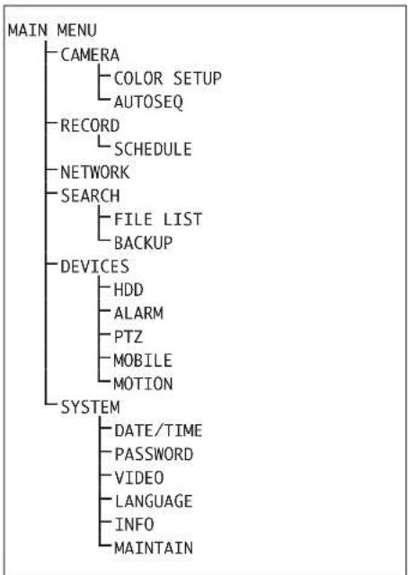
9Menu structure
An overview of the menus:
CAMERA
Camera name, selection of cameras for live surveillance, time indication
COLOR SETUP
Setting of camera images (colour, brightness, contrast)
AUTOSEQ
Settings for the sequence function
RECORD
Settings for recording (resolution, quality, audio)
SCHEDULE
Weekly schedule for time-controlled or alarm-controlled recording
NETWORK
Parameters for network connection
SEARCH
Overview of the recordings sorted according to date/camerachannel/reasonforrecording(FILE LIST), replay and export (BACKUP) of a recording
HDD
Information concerning the hard disk and its recording capacity, overwrite behaviour, option for formatting the hard disk or a storage medium connected via USB
ALARM
Response of the sensors at the alarm inputs, options for alarm triggering in case of video signal loss / lack of storage space / hard disk failure, closing time of the alarm output, the video recording and the audible alarm signal, settings for e-mail transmission in case of alarm
PTZ
Settings for cameras to be controlled via the RS-485 data bus, selection of cameras for the automatic surveillance tour
MOBILE
Parameters for remote control of the recorder via a mobile phone
MOTION
Settings for automatic motion detection via the camera images (sensitivity, detection zones)
DATE/TIME
Setting of date and time, indication format, time zone, automatic change to daylight saving time
PASSWD
Definition of a user password and administrator password against unauthorized operation
VIDEO
Selection of the video system used and setting of the resolution for the VGA output
LANGUAGE
Selection of menu language
INFO
Indication of type of unit, firmware version and definition of the MAC address
MAINTAIN
Options for regular restart, manual restart, firmware update
Alternatively to the way described via the menu list, it will also be possible to activate the main menu (figure 10) directly with the button MENU / ESC (7) or MENU (32):
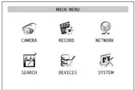
10) Main menu
To activate a submenu, click the corresponding icon with the left mouse button or select it with the buttons and (10), (10)and (13) onthe recorder
or , , (29) on the remote control and confirm with the button SEL / EDIT (9) or SEL (33).
To exit the main menu or a submenu, click the right mouse button or press the button MENU / ESC (7) or MENU (32).
6.2 Basic settings
6.2.1 Changing the menu language
The preset language for the settings and dialogues in the OSD menu is English. This instruction manual refers to this language. To change the language:
1) Activate the main menu (MAIN MENU, fig. 10).
2) Activate the submenu SYSTEM/SYSTEM SETUP (fig. 11).
4) Select the list field with the mouse or by pressing the button SEL / EDIT (9) or SEL (33) and select the desired language from the list. For this purpose, click the language with the left mouse but
ton or mark it via the buttons and (8or 29) and then press the button SEL / EDIT or SEL.

5) To store the settings, click the button APPLY, then confirm the message inserted "Saved successfully!" by clicking the button OK. The system will then be restarted with the language selected.
6) To exit the submenu without accepting the changes, click the button EXIT or click the right mouse button or press the button MENU / ESC (7) or MENU (32):
6.2.2 Video settings
In the factory, the recorder has been set to the European video standard PAL; however, it will be possible to set it to the American video standard NTSC, if required. In addition, for using the VGA output, various resolutions will be available:
To change the video settings:
1) Activate the MAIN MENU (fig. 10).
2) Activate the submenu SYSTEM/SYSTEM SETUP (fig. 11).
3) Activate the submenu VIDEO/VIDEO SETUP (fig. 13).
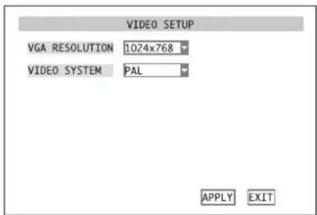
(13)SubmenuVIDEOSETUP
4) In the list field next to VGA RESOLUTION, select the desired resolution for the VGA output (pixels horizontal × vertical).
For this purpose, select the list field with the mouse or by pressing the button SEL/EDIT (9) or SEL (33). Click the resolution with the left mouse button or mark it via the buttons and (8 or 29), then press the button SEL/EDIT or SEL.
5) Click the list field next to VIDEO SYSTEM with the mouse or mark it via the button (8 or 29), then press the button SEL/EDIT (9) or SEL (33). Select PAL or NTSC and confirm with the button SEL/EDITorSEL.
6) To store the settings, click the button APPLY, then confirm the message inserted "Saved successfully!" by clicking the button OK. If the video system has been changed, the system will then be restarted.
7) To exit the submenu, click the button EXIT or the right mouse button or press the button MENU/ESC (7) or MENU (32):
6.2.3 Camera names
For each camera channel, it will be possible to insert a name of up to eight characters in the image. To name the cameras and to position their names:
1) Activate the MAIN MENU (fig. 10).
2) Activate the submenu CAMERA/ DISPLAY SETUP (fig. 14).
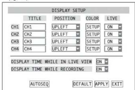
(14) Submenu DISPLAY SETUP
3) In the column TITLE, click the first character to be changed in the line of the camera channel to be set. A set of characters with upper-case letters will appear (fig. 15).
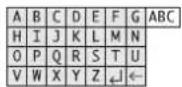
15Set of characters with upper-case letters
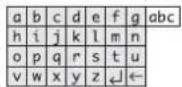
- Set of characters with lower-case letters
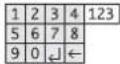
17)Set of characters with numbers
Click the letter desired. Now enter the next letter. To change to the lower-case letters (fig. 16), click ABC and to change to the numbers (fig. 17), click abc. If you click 123, you will return to the upper-case letters. To delete the last character entered, click the icon . To terminate the input, click the icon .
For operation without mouse, first select the input field with the buttons and (8) (10) and (18) on the recorder or , ▲(29) on the remote control and confirm with the button SEL / EDIT (9) or SEL (33). The first character will be highlighted now. Select the character position to be changed with the buttons and (13) or and (20) and confirm with SEL / EDIT (9) or SEL (33). Now the set of characters with upper-case letters will appear. To enter and delete a character and to change the sets of characters, as described for mouse operation, use the buttons ▲, ▼ (8) (10), ▲ (13) or ▲, ▲, ▲, ▲ (29) and then confirm with SEL / EDIT (9) or SEL (33). After completing the input via the icon J, exit the input field by pressing the button MENU / ESC (7) or MENU (32).
Enter the names of the other camera channels in the same way.
4) In the column POSITION, define in the corresponding list field if and where the name is to be inserted in the image:
UPLEFT insertion at the top on the left
DOWNLEFT insertion at the bottom on the left
UPRIGHT insertion at the top on the right
DOWNRIGHT insertion at the bottom on the right
OFF
5) For DMR-188 only: For setting the camera channels 5-8, click NEXT. Then click PREV. to return to the previous menu page.
6) To reset all settings of this submenu to the factory settings, click the button DEFAULT.
7) To store the settings, click the button APPLY, then confirm the message inserted "Saved successfully!" by clicking the button OK.
8) To exit the menu, click the button EXIT or the right mouse button or press the button MENU / ESC (7) or MENU (32).
6.2.4 Date and time
The recorder is equipped with a clock. Due to a battery, this clock will still run when the recorder is switched off or in case of power failure. To set the date and time:
1) Activate the MAIN MENU (fig. 10).
2) Activate the submenu SYSTEM/SYSTEM SETUP (fig. 11).
3) Activate the submenu DATE/TIME/TIMESETUP (fig. 18).
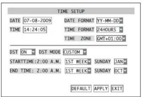
18 Submenu TIME SETUP
4) In the list field next to DATE FORMAT, select the desired format for indicating the date: MM/DD/YY or YY-MM-DD
Then enter the current date in the input field next to DATE. It will be entered like the camera name (62 chapter 6.2.3).
5) In the list field next to TIME FORMAT, select 24-hour or 12-hour indication. Then enter the current time in the input field next to TIME. If the 12-hour format has been selected, define AM or PM in the additional list field.
6) In the list field next to TIME ZONE, select the time zone of the place of application (e.g. GMT for UK).
7) In the list field next to DST, select automatic change for daylight saving time (ON) or not (OFF). If ON has been selected, define in the list field next to DST MODE if the change is to be effected at the usual times (DEFAULT) or at a time defined individually (CUSTOM). If CUSTOM has been selected, define in the list field next to STARTTIME if the change to daylight saving time is to be made in the first, second, third or fourth week and next to SUNDAY in which month the change to daylight saving time is to be made on a Sunday at 2 a.m. In the line below it, define the date for the change back to standard time.
8) To reset all settings of this submenu to the factory settings, click the button DEFAULT.
9) To store the settings, click the button APPLY, then confirm the message inserted "Saved successfully!" by clicking the button OK.
10) To exit the submenu, click the button EXIT or the right mouse button or press the button MENU / ESC (7) or MENU (32).
If the clock does not keep the current time until the recorder is switched on again, the battery (button cell inside the recorder) may be exhausted und must be replaced.
6.2.5 Correcting image properties
The properties of the camera images may be corrected, if required. For this purpose, in the submenu CAMERA/DISPLAY SETUP (fig. 14), click SETUP in the line for the camera channel to be set and select it with the buttons and and and (0) and (13) on the recorder or A, (29) on the remote control and confirm with the button SEL/EDIT (9) or SEL (33).
The submenu for setting the image properties COLOR SETUP (fig. 19) will appear:
For DMR-188 only:
For setting the camera channels 5-8, click NEXT first. Then click PREV. to return to the previous menu page.
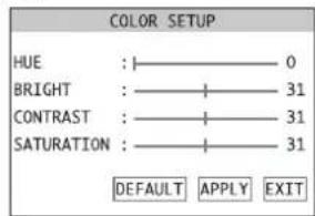
19 Submenu COLOR SETUP
To set the values for HUE, BRIGHT, CONTRAST and SATURATION, move the sliding controls shown on the menu. If no mouse is connected, select the corresponding control with the buttons and (8, 29) and change the value with the buttons (串) and (13) or (29) .
To reset all settings of this submenu to the factory settings, click the button DEFAULT.
To store the settings, click the button APPLY, then confirm the message inserted "Saved successfully!" by clicking the button OK.
To exit the submenu, click the button EXIT or the right mouse button or press the button MENU /ESC (7) or MENU (32).
7 Live Surveillance
The display of the camera images for live surveillance is independent of the recording activity of the recorder.
To display a camera image as a full image, double-click it with the mouse pointer (left mouse button). If a camera can be remote-controlled, it can be operated in full image display (E3 chapter 11). To return to the split screen, double-click once again.
Alternatively, switchover will also be possible via the buttons on the recorder on or the infrared remote control.
DMR-180 and DMR-184: Select the camera channel CH 1, CH 2, CH 3 or CH 4 for full image display with the buttons l & 口 & 口 l & 口 & 口 with the numerical keys (27) of the remote control. To return to the split screen, press the button l & 口 & 口 or the button ALL (28).
DMR-188: Select the desired channel CH 1 to CH 8 for full image display with the buttons and (5) or directly select it with the numerical keys (27) on the remote control. To return to the split screen, press the button or the button ALL (28). Each time the button is pressed again, the image will switch between quad display of channels CH 1 to CH 4, CH 5 to CH 8 and simultaneous display of all eight channels.
7.1 Display options
To define the camera image for live surveillance and to define if date and time are to be inserted and to configure the sequence function:
1) Activate the MAIN MENU (fig. 10)
2) Activate the submenu CAMERA/DISPLAY SETUP (fig. 14).
3) In the column LIVE, define for each camera channel in the list field if it is to be displayed for live surveillance (ON) or not (OFF). The setting will also determine if there will be an audio signal for the corresponding channel.
4) For DMR-188 only: For setting the camera channels 5 - 8, click NEXT. Then click PREV. to return to the previous menu page.
5) In the list field next to DISPLAY TIME WHILE IN LIVE VIEW define if the date and the time are to be inserted for live surveillance (ON) or not (OFF).
6) To configure the sequential switching, click AUTOSEQ chapter 7.2).
7) To reset all settings of this submenu to the factory settings, click the button DEFAULT.
8) To store the settings, click the button APPLY, then confirm the message inserted "Saved successfully!" by clicking the button OK.
9) To exit the submenu, click the button EXIT or the right mouse button or press the button MENU / ESC (7) or MENU (32).
7.2 Configuring the sequence function
With the sequence function, the display will change automatically during live surveillance. To configure the sequence function, activate the submenu AUTOSEQ (fig. 20) via the button AUTOSEQ in the submenu CAMERA/DISPLAY SETUP (fig. 14).
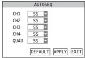
20 Submenu AUTOSEQ
1) In the list field next to the camera channels, select the dwell time (in seconds) for full image display of each camera or select OFF if the camera is not to be displayed as a full image for the sequence function. For QUAD, define if the quad display is to be shown and define its dwell time.
DMR-188: Apart from the times for full image displays of channels 1 to 8, it will also be possible to define the times for the quad displays of channels 1 to 4 and 5 to 8 and for the display of all eight channels.
2) To reset all settings of this submenu to the factory settings, click the button DEFAULT.
3) To store the settings, click the button APPLY, then confirm the message inserted "Saved successfully!" by clicking the button OK.
4) To exit the submenu, click the button EXIT or the right mouse button or press the button MENU / ESC (7) or MENU (32).
7.3 Activating/deactivating the sequence function
To start the sequence function, press the button PAUSE (1) on the recorder or on the remote control (1) after exiting the OSD menu. AUTOSEQ will be inserted and the dwell time for each view will be counted down to 0 before proceeding to the next view. Camera channels without video signal will be skipped automatically.
To end the sequence function, press the button once again.
8 Recording
The video signals will be recorded on the internal hard disk. This hard disk must be formatted prior to the first recording by the video recorder. To save storage space, the video signals will be compressed according to the highly efficient standard H.264 (MPEG-4 /AVC). The image quality of the recording (and thus the compression rate) will be adjustable.
8.1 General settings for recording
Prior to the first recording, define the camera channels intended for recording, the resolution and the quality is to be used, define if an audio signal is to be recorded as well and the maximum size of the video files.
1) Activate the MAIN MENU (fig. 10).
2) Activate the submenu RECORD/RECORD SETUP (fig. 21).
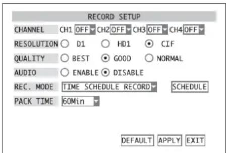
21 Submenu RECORD SETUP
3) In the line CHANNEL, define for each camera channel in the list field if it is to be available for recording (ON) or not (OFF).
4) In the line RESOLUTION, select the resolution (pixels horizontal × vertical) for recording the video signal. The resolution will also depend on the video standard used (153" chapter 6.2.2).
DMR-188: It will not be possible to select the resolution; recordings will always be made with the resolution CIF.
| PAL | NTSC | |
| D1 | 704 × 576 | 704 × 480 |
| HD1 | 704 × 288 | 704 × 240 |
| CIF | 352 × 288 | 352 × 240 |
5) In the line QUALITY, select the quality for recording the video signal. With increased quality (NORMAL GOOD BEST), the storage space required will also be increased.
6) In line AUDIO, define if the audio signals are to be recorded as well (ENABLE) or not (DISABLE). DMR-188: This recorder only has one audio input. In the list field next to AUDIO REC, it will be possible to select the camera channel for recording the audio signal. If OFF is selected, no audio signal will be recorded.
7) In the list field PACK TIME, select the maximum size of the video files, i.e. the recording time after which a new file will be created automatically.
8) To reset all settings of this submenu to the factory settings, click the button DEFAULT.
9) To store the settings, click the button APPLY, then confirm the message inserted "Saved successfully!" by clicking the button OK.
10) To exit the menu, click the button EXIT or the right mouse button or press the button MENU / ESC (7) or MENU (32).
Furthermore, it can be defined if the date and the time inserted in the image are also to be recorded:
1) Call the submenu CAMERA/DISPLAY SETUP (fig. 14) via the main menu (fig. 10).
2) In the list field next to DISPLAY TIME WHILE RECORDING, define if the date and the time in the image are also to be recorded (ON) or not (OFF).
3) To store the settings, click the button APPLY, then confirm the message inserted "Saved successfully!" by clicking the button OK.
4) To exit the submenu, click the button EXIT or the right mouse button or press the button MENU / ESC (7) or MENU (32).
8.1.1 Configuring/deleting the hard disk
1) Activate the menu Devices/ DEVICE MANAGEMENT (fig. 22) in the main menu (fig. 10).
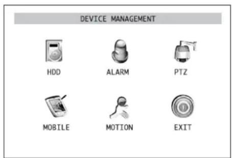
22 Submenu DEVICE MANAGEMENT
2) Activate the submenu HDD/HDD MANAGEMENT (fig. 23).
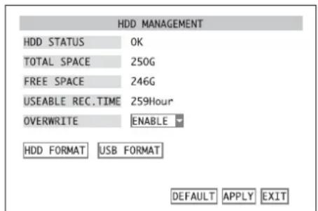
(23) Submenu HDD MANAGEMENT
In the line HDD STATUS, the status of the hard disk will be indicated.
OK: The hard disk is ready for recording.
No Disk Found: No hard disk installed.
Not Formatted: The hard disk has not been formatted or has not been correctly formatted. (The recorder will use its own format which is not compatible to the usual formats for computers.)
In the line TOTAL SPACE, the total hard disk capacity will be indicated; in the line FREE SPACE, the free storage space will be indicated.
The line USEABLE REC. TIME will indicate the recording time, depending on free storage space and the recording quality and resolution set in the submenu RECORD/RECORD SETUP (chapter 8.1, fig.21).
3) If the hard disk has not been formatted for use in this recorder or if all recordings previously made are to be deleted (it will not be possible to delete individual recordings from the hard disk), click the button HDD FORMAT.
To start formatting, click OK in the confirmation prompt pointing out that formatting will delete all data on the hard disk. To abort the procedure, click CANCEL.
After successful formatting, confirm the message "Formatted successfully!" with OK.
Now the recorder will be restarted automatically. Then reactivate this submenu HDD/HDD MANAGEMENT (fig. 23).
4) In the line OVERWRITE, define if the oldest recordings are to be overwritten automatically (ENABLE) or not DISABLE) when the hard disk is full.
5) To reset all settings of this submenu to the factory settings, click the button DEFAULT.
6) To store the settings, click the button APPLY, then confirm the message inserted "Saved successfully!" by clicking the button OK.
7) To exit the submenu, click the button EXIT or the right mouse button or press the button MENU / ESC (7) or MENU (32).
8.2 Recording control
If camera channels have generally been selected for recording (15) chapter 8.1), there will be different ways to start a recording.
8.2.1 Permanent recording
For permanent recording of the desired camera channels, select the option ALWAYS in the line REC. MODE of the submenu RECORD/RECORD SETUP (chapter 8.1, fig. 21) and confirm with APPLY. All channels for which ON has been selected in the line CHANNEL will be recorded once the recorder has been switched on and camera signals have been applied.
8.2.2 Manual start of recording
It will also be possible to start a recording manually. For this purpose, press the button REC (5) on the recorder or 31) on the remote control or activate the item START RECORD in the menu list (insertion via the right mouse button 6 chapter 6.1, fig.8).
All channels set to ON in the line CHANNEL in the menu RECORD/ RECORD SETUP chapter 8.1, fig.21) will be recorded.
To end the recording, press the button STOP (14) on the recorder or (■) on the remote control or activate the item STOP RECORD in the menu list (insertion via the right mouse button).
8.2.3 Time-controlled recording
It will also be possible to control the recording automatically via a schedule defined individually for each camera channel.
1) In the submenu RECORD/RECORD SETUP (127 chapter 8.1, fig. 21) in the line REC. MODE, select the option TIME SCHEDULE RECORD and click the button SCHEDULE.
The submenu for the SCHEDULE (fig. 24) will appear. It contains a weekly schedule with the days Sunday to Saturday in the vertical and the hours of the day in the horizontal.
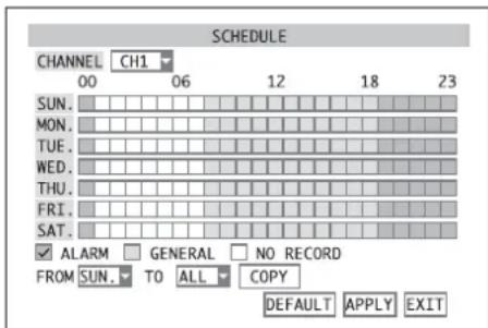
24 Submenu SCHEDULE
2) Next to CHANNEL in the list field, select the camera channel for which a recording schedule is to be defined. If the same schedule is intended for all channels to be recorded, select the option ALL.
3) To enter the type of recording for each hour, tick off the corresponding type in the line below the schedule and then mark the periods.
Tick off ALARM and then click all fields for the hours when a recording is to be started in case of alarm triggering only (detailed information concerning alarm triggering can be found in the chapter below). These fields will be red.
Tick off GENERAL and then click all fields for the hours of permanent recording. These fields will be green.
Tick off NO RECORD and then click all fields for the hours without recording. These fields will be black.
For operation without a mouse, first select a field with the buttons and (8) 10and 13 on the recorder or A,2V29 on the remote control and confirm with the button SEL/EDIT (9) or SEL (33).
4) To simplify the input, there is an additional copy function which will allow you to copy the settings made for a day of the week to the lines for the other days:
In the list field next to FROM, set the preset line of the corresponding day. Then select the copy target (the day of the week or ALL for all days of the week) on the right next to T0. Then click the button COPY.
5) To reset all settings of this submenu to the factory settings, click the button DEFAULT.
6) To store the settings, click the button APPLY, then confirm the message inserted "Saved successfully!" by clicking the button OK.
7) To exit the submenu, click the button EXIT or the right mouse button or press the button MENU / ESC (7) or MENU (32).
8.2.4 Alarm-controlled recording
A recording can also be started by a movement detected in the camera image or via an external sensor connected to the corresponding alarm input SENSOR (24) of the corresponding camera channel. The settings for alarm detection and the alarm evaluation are described in chapter 10.
The requirements for starting an alarm-controlled recording are general approval of the camera channel for recording (13 chapter 8.1), presence of a video signal and selection of time-controlled recording (14 chapter 8.2.3) with the setting "Alarm recording" at the time of alarm triggering.
8.2.5 Insertions during recording
In addition to flashing of the LED HDD (4), the recording status will be indicated via the following icons in the corresponding camera image:
time-controlled recording, permanent recording or manual recording
recording triggered via an alarm input
recording triggered via the internal motion detector
no start of recording because there is no hard disk, the hard disk has not been formatted or the hard disk is full (if the overwrite mode has been deactivated chapter 8.1.1, step 4 OVERWRITE = DISABLE)
8.2.6 Storage according to type of recording
According to the start of the recording, the video data will be stored as "alarm recording" or "normal recording". For replay, the files can be selected according to their type.
If an alarm is triggered via an alarm input or the internal motion detector during a permanent or time-controlled recording, the recorder will create a new file of the type "alarm recording" on the hard disk. At the end of the alarm recording time (10.1, DURATION), recording will be continued with a new file of the type "normal recording".
However, with a recording started manually, a file of the type "normal recording" will be stored continuously, even if in the meantime an alarm is triggered and the icon or is inserted (83 chapter 8.2.5).
9 Replay
To replay a recording:
1) Activate the submenu SEARCH/VIDEO SEARCH (fig. 25) either via the main menu (fig. 10), the menu list (13) chapter 6.1, fig. 8) or, if the menu has been deactivated, via the button PLAY (12) or (1).
DMR-188 is additionally equipped with the button SEARCH (B) for direct activation of this submenu.
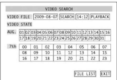
23SubmenuVIDEOSEARCH
2) If you know the precise time of a recording, enter the date and the time in the corresponding input fields in the upper line (detailed description of an input 123 chapter 6.2.3). Then click the button PLAYBACK.
If the replay is started, continue with step 5).
Note: If you enter a time which is close to the end of the recording, you will not be able to replay it with this selection method. To replay this recording, enter an earlier time or use the direct selection of files for the reproduction described in step 7).
3) If you only know the approximate period of time when the recording was made, enter the desired date or any date in the desired month and click the button SEARCH.
In the overview, the selected month will be shown with the 24 hours of the day selected below it. Recordings were stored in the periods of time highlighted in colours: Green highlights are "normal recordings" made via permanent recording, time-controlled recording or manual recording. However, red highlights are recordings triggered by an alarm (via an alarm input or via the internal motion detector).
To show the overview of another day, click it in the overview of the month or select it with the buttons and (8) and (10) and (13) on the recorder or , (29) on the remote control and confirm with the button SEL / EDIT (9) or SEL (33).
4) To replay the recordings, click the desired period of time in the overview of the day (the overview is divided into half-hour sections) or select it with the buttons and (8) and (10) and (13) on the recorder or , (29) on the remote control and confirm with the button SEL/EDIT (9) or SEL (33).
Note: If another recording is available within a half-hour section, you will not be able to replay it with this selection method. To replay this recording, use the direct selection of files described in step 7).
5) The replay will always start with a split screen; however, like for live surveillance, the different views can be switched over with a double click of the left mouse button or with the corresponding buttons (13 chapter 7).
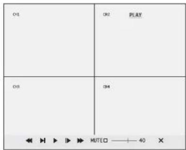
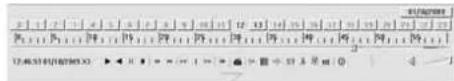
26) Replay control
6) If the mouse pointer is moved to the lower edge of the screen, a toolbar for controlling the replay will appear (fig. 26). Click the icons with the mouse:
PAUSE, FRAME - to interrupt the replay and to continue in frames
PLAY - to continue the replay
SLOW1/2, SLOW1/4, SLOW1/8 - for replay in slow motion at 12 , 14 or 18 of the normal speed
2X,>>4X,>>8X-for replay at double, four-fold or eight-fold speed
<<2X,<<4X,<<8X-for reverse replay at double,four-fold or eight-fold speed
MUTED If the box is not ticked off, adjust the volume for audio replay with 40 For muting, tick off the box.
X toabort the replay
Alternatively, it will also be possible to control the replay via the buttons on the recorder or on the remote control:
PAUSE(1)or(31) PAUSE,FRAME
PLAY(2) or (31) = PLAY
FWD (13) or (31) = >>2X, >>4X, >>8X
REW (10) or (31) = <<2X, <<4X, <<8X
STOP (4) or (31) abort of replay
DMR-188 only: The audio replay will be muted with the button MUTE (5).
After aborting or ending a replay, the submenu SEARCH/VIDEO SEARCH (fig. 25) will reappear.
7) For specific selection of a video recording in the form of a single video file, click the button FILE LIST. The file list of the day selected (example: fig. 27) will be indicated.
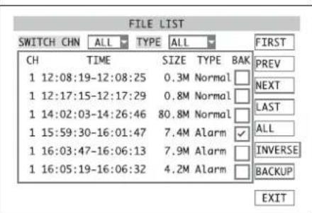
7 Submenu FILE LIST
For each file, its camera channel (CH), the recording time (TIME), the file size in MB (SIZE) and the type of recording (TYPE) will be indicated.
Via the list field next to SWITCH CHN, it will be possible to define if recordings of all camera channels (ALL) or recordings of a particular channel only (CH1, CH2, ...) are to be listed. Next to TYPE, define if recording of both types (ALL), "normal recordings" only (NORMAL) or recordings
triggered by an alarm only (ALARM) are to be listed (13 chapter 8.2.6).

If the list extends over several screen pages, scroll through the pages with the buttons on the right:
FIRST first menu page (oldest recordings of the day selected)
PREV. previous page
NEXT next page
LAST last page (latest recordings of the day selected)
For replay, click a video file in the list or select it with the buttons and (and) and
(13) on the recorder or,▲, (26) on the remote control and confirm with the button SEL/EDIT (9) or SEL (33). The replay will be controlled as described in steps 5) and 6).
To exit the list and to return to the submenu SEARCH/VIDEO SEARCH, click the button EXIT.
Note: It will not be possible to delete individual recordings from the hard disk; it will only be possible to delete (format) the entire hard disk (13 chapter 8.1.1).
9.1 Exporting video files
For backup or for viewing on a computer, it will be possible to copy the video files recorded on the internal hard disk to a storage medium (USB stick or hard disk) connected to the USB port [22]. [After connection, it may take a few seconds until the storage medium has been recognized.]
1) As described in chapter 9, select a particular day when video recordings were made and activate the file list (example: fig. 27).
2) In the column BAK, click the box next to the desired video files or select it with the buttons and (8) and (10) and (13) on the recorder or (29) on the remote control and confirm with the button SEL / EDIT (9) or SEL (33). It will be ticked off. When it is clicked again, the tick mark will be removed.
If the list extends over several screen pages, scroll through the pages with the buttons on the right:
FIRST first menu page (oldest recordings of the day selected)
PREV. previous page
NEXT next page
LAST last page (latest recordings of the day selected)
The following buttons will simplify the selection:
ALL all files on this screen page will be ticked off
INVERSE the selection on this screen page will be inversed, i.e. for all files selected, the tick mark will be removed; all other files will be ticked off
When scrolling through the menu pages, the selection will be maintained.
3) If all desired files have been selected, click the button BACKUP.
If the message "No file selected!" appears, no file has been selected.
If the message "No USB device found!" appears, no storage medium has been connected to the USB port or the medium connected has not been formatted or has not correctly been formatted (13 chapter 9.1.1).
While copying, the total number of files to be copied and the progress of this process will be indicated. After successful copying, the message "Backup Successfully!" will appear.
Confirm all messages by clicking the button OK or confirm with the button SEL/EDIT (9) or SEL (33).
The recorder will create a directory "RecordFile" on the storage medium and will store the files in *.264 format (H.264 compressed) in it. The file name will contain the channel number, the date and the time of recording. The computer programs provided will allow reproduction on a computer and conversion to AVI format.
GB 9.1.1 Formatting the USB storage medium
It will be possible to format a USB stick or a hard disk connected to the USB port by the recorder for deleting all data copied on it. The FAT format used here will be compatible with most computers.
1) Activate the submenu DEVICES/ DEVICE MANAGEMENT (fig. 22) in the main menu (fig. 10).
2) Activate the menu HDD/HDD MANAGEMENT (fig. 23, chapter 8.1.1).
3) Click the button USB FORMAT. To start formatting, click OK in the confirmation prompt pointing out that formatting will delete all data on the storage medium. The procedure will be aborted with CANCEL.
4) After successful formatting, confirm the message "Formatted successfully!" with OK.
9.2 Replay of recordings with the program PLAYBACK
The program PLAYBACK provided will allow to replay exported video files on a computer not connected to the recorder. For this purpose, connect the USB storage medium (USB stick or hard disk) on which the files have been stored to the computer. It will also be possible to replay video files stored on a computer by remote access (13 chapter 14.2) with the program PLAYBACK.
For installation, start the program "PlaybackSetup[...]exe" and follow the instructions on the screen. After installation, start the program file "Playback.exe".
9.2.1 Opening video files
9.2.1.1 Opening a single video file
To open a particular H.264 video file (file extension .264), double-click it or start the program PLAYBACK first, then open the file via the menu item "File Open Local File". Make sure that the option "264 Files (.264)" has been selected in the window "Open" in the list field "File type". The program will start with the view shown in fig. 28 and will start replaying the file.
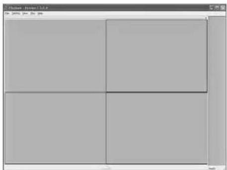
28 Start screen of the program PLAYBACK
9.2.1.2 Opening several files at the same time or searching for a video file
When searching for a video file recorded at a particular time, it will be possible to open a whole directory with all subdirectories or a whole drive and search for video recordings.
1) For searching a directory, activate the menu item "File Open Local Dir", for searching a whole drive, activate the menu item "File Open Local Disk".
2) In the directory structure shown, define the directory or drive to be searched. The computer will now search the corresponding storage locations and will meanwhile show "Browsing file, ..."
3) If the toolbar for replay (fig. 32) is not visible yet, click the button to insert it.
4) Above the toolbar on the right, you will find a button with the date of the first recording found. For replaying recordings of another date, click this button. A window with a calendar (fig. 29) will appear where another date can be selected. The days when video recordings were made will be highlighted.
Click the desired day and confirm with "OK" (or click "Cancel" to abort).
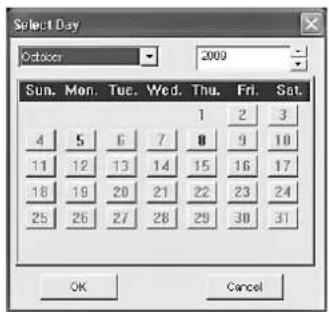
29 "Select Day"
5) The date selected will appear on the button above the toolbar. Below it, there will be a button for every hour of the day. The hours for which video recordings are available will be highlighted. To select a recording, click one of these buttons.
6) In the minute scale below the hour buttons, the period of time for available recordings will be marked by a coloured line. Select a particular time on this line with the mouse.
If video files of different camera channels made at the same time are available, it will be possible to replay them at the same time in a split window.
9.2.1.3 Opening several independent players
To compare video recordings not made at the same time, it will be possible to open up to four independent players on a screen. The players will also be able to access different storage locations of the video files.
1) Activate the menu item "File Open Multiple Disk". The window "Open Multiple Disk" (fig. 30) will appear.
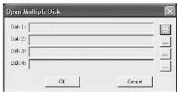
30"Open Multiple Disk
2) For each player "Disk 1" to "Disk 4" required, click the button "... and in the directory structure shown define the directory or drive with the video recordings to be replayed.
3) Exit the window "Open Multiple Disk" with "OK". The computer will now search the corresponding storage locations and will meanwhile show "Browsing file, ..."
As described in chapter 9.2.1.2, recordings of a particular recording time can be selected separately for each player. The replay will be controlled via a separate toolbar for each player (3 chapter 9.2.2). Via the mouse, the windows of the players can be varied in size and arrangement (e.g. fig. 31) or the windows of players not required can be closed. The menu item "View Default Multiple Videobar View" will reset the arrangement to basic setting.
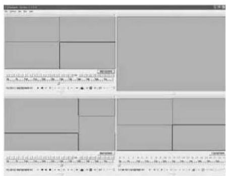
31 Sample screen "Multiple Disk"
9.2.2 Replaying video recordings
Control of the replay will be possible via the menu "Play" or via the toolbar (fig. 32). If the toolbar is not visible, activate it via the button . To deactivate it, click the button .
32 Toolbar for the replay
The replay functions:
forward replay menu: "Play
reverse replay
interrupt replay menu:"PlayPause"
stop replay menu:"Play Stop"
reverse one frame menu: "Play Backward Frame"
```bash
advance one frame menu: "Play Forward Frame"
reduce replay speed menu:"PlayDecrease Rate"
normal replay speed
increase replay speed menu: "Play Increase Rate"
skip one hour menu:"Play Next Hour
reduce number of channels displayed
display all channels at the same time menu: "Play All Video"
increase number of channels displayed volume setting for video files with audio signals
/ mating by clicking the speaker icon or via the menu item "Play Mute"
At the bottom on the left, the recording time of the recording currently replayed will be indicated. The current replay speed can be found on the right of it:
X1 = normal speed
X2-X16 = 2-fold to 16-fold speed
X1/2-X1/16= 1/2 to 1/16 of normal speed
Like for the recorder, the display will also be switched over between full image display of a single camera channel and simultaneous display of several channels when double-clicking the image.
9.2.3 Processing video files
9.2.3.1 Storing snapshots
When replaying a recording, it will be possible to store a snapshot as an image file in Windows bitmap format (*.BMP).
1) If several channels are replayed at the same time, select the image to be stored with the mouse. The image selected will have a coloured frame.
2) In the toolbar, click the icon "Capture Bitmap" or activate the menu item "Play Capture Picture".
3) In the window now appearing, define the file name and the storage location for the image file and confirm with "OK".
9.2.3.2 Extracting a passage
The clip function will allow to select any passage within all open video files and to store it as a new file respectively.
1) Replay the recording to find the beginning of the passage or select the corresponding spot on the time scale with the mouse.
2) At the beginning of the passage to be extracted, click the button ST"Start Operation". A small vertical line will mark this point of time on the scale.
3) When the replay is at the end of the desired passage, click the button "Clip File". The window "Time Range" (fig. 33) will appear. It will show the time of the beginning "From:" and of the end "To:" of the passage selected.
To readjust the two points of time, change the values in the fields for year, month, day, hour, minute and second.
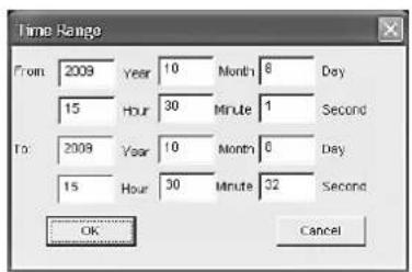
33"Time Range"
4) If all entries are correct, click the button "OK" (or click "Cancel" to abort). In the directory structure now indicated, define the storage location for the new video files. The program will create a new folder "Clip Data" and will store in it the new files for all channels which have not generally been deactivated for display (13 chapter 9.2.4.1 "Play The Video").
9.2.3.3 Storing a video file in AVI format
The files recorded by the video recorder and the video files extracted via the clip function, will be compressed according to the H.264 standard. To replay these recordings with programs not yet supporting this standard, store the files or any passages of the files in AVI format.
1) Replay the recording to find the beginning of the passage.
2) At the beginning of the passage to be stored, click the button "Start Operation". A small vertical line will mark this point of time on the scale.
3) When the replay is at the end of the desired passage, click the button change to AVI". The window "Time Range" (fig. 33) will appear. It will show the time of the beginning From:" and of the end To:of the passage selected.
To readjust the two points of time, change the values in the fields for year, month, day, hour, minute and second.
4) If all entries are correct, click the button "OK" (or click "Cancel" to abort). In the window now appearing, define the file name and the storage location for the AVI video file and confirm with "OK".
If several files for the time selected are open, an individual file will be stored for each camera channel (if the channel has not generally been deactivated for display chapter 9.2.4.1 "Play The Video"). Each time an AVI video file has been stored, the window for defining the file name and the storage location for the next AVI video file will reappear.
Storing long passages may take some time.
9.2.3.4 Deleting video files
This function will delete video files for a time to be entered.
1) Replay the recording to find the beginning of the passage to be deleted or select the corresponding spot on the time scale with the mouse.
2) At the beginning of the passage to be deleted, click the button Start Operation". A small vertical line will mark this point of time on the scale.
3) When the replay is at the end of the desired passage or the point of time has been defined on the time scale with the mouse, click the button "Delete File". The window "Time Range" (fig. 33) will appear. It will show the time of the beginning "From:" and of the end "To:" of the passage selected.
To readjust the two points of time, change the values in the fields for year, month, day, hour, minute and second.
4) If all entries are correct, click the button "OK" (or click "Cancel" to abort). All files entirely recorded within the time frame entered will be deleted.
Notes:
- With this function, it will not be possible to delete particular sections within a video file.
The function will not only affect the file of the channel selected; all open files of this time will be deleted (if the channel has not generally been deactivated for display chapter 9.2.4.1 "Play The Video").
9.2.4 Changing settings
The menu "Setting" will allow to change the settings for selecting camera channels, audio replay and arrangement of windows.
9.2.4.1 Selecting camera channels
1) Activate the menu item "Setting Video Play Setting Normal Video Bar". The window "Play The Video Setting" will open (fig. 34).
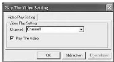
34"Video Play Setting
2) In the list field "Channel", successively select the camera channels used and tick off "Play The Video" for each channel if the recordings of the channel are to be replayed. If display of the channel is not desired, remove the tick mark.
3) Click "OK" to accept the change. Stop a replay being reproduced with st so that the changes will have an effect on the display.
If several independent players are used at the same time (12 chapter 9.2.1.3), the settings will be made separately for all players in the same way via the menu items "Setting Video Play Setting First/ Second / Third / Fourth Video Bar Of Multiple Disk".
9.2.4.2 Selecting audio replay
For replaying the audio signal with a video recording:
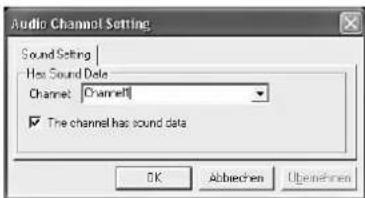
1) Activate the menu item "Setting Audio Channel Setting Normal Video Bar". The window "Audio Channel Setting" will open (fig. 35).
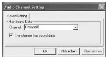
35"Audio Channel Setting
2) In the list field "Channel", successively select the camera channels used and tick off "The channel has sound data" for each channel if the recordings contain audio signals. Remove the tick mark if no audio recordings are available for the channel or if they are not to be replayed.
3) Click "OK" to accept the change. Stop a replay being reproduced with first so that the changes will have an effect on the audio replay.
If several independent players are used at the same time (13 chapter 9.2.1.3), the settings will be made separately for all players in the same way via the menu items "Setting Audio Channel Setting First/ Second / Third / Fourth Video Bar Of Multiple Disk".
9.2.4.3 Defining window arrangements
If several camera channels are replayed at the same time, click the buttons and in the toolbar (fig. 32) to change between views with a different number of display fields. Define which channel is to be reproduced in which display field in the individual views as follows:
1) Activate the menu item "Setting Video Channel Split Setting". The window "Video Channel Split

Setting" will open (fig. 36, example with 5 display fields).
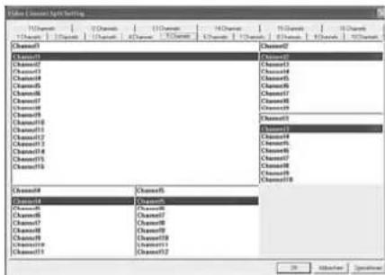
36"Video Channel Split Setting - 5 Channels
2) Via the tabs in the upper part, select the views to be changed from the display fields 1-16 (1-16 Channels).
3) For each display field of this view, enter in the input field or select from the list which camera channel is to be displayed there.
An error message will appear if the same channel has inadvertently been selected for several fields of a view.
4) If all desired views have been adapted to your individual requirements, click "OK" to accept the changes.
GB 10 Alarm Functions
It will be possible to trigger an alarm via the internal motion detector, via an alarm input for external sensors (e.g. light barrier or motion detector), if a video signal is lost or if the hard disk is full or missing. Depending on the configuration of the recorder, there are various responses to an alarm, e.g. start of a recording, activation of the alarm output, acoustic alarm signal, insertion of a message on the screen, transmission of an e-mail with a photo of the object triggering the alarm.
10.1 Alarm configuration
1) Activate the menu Devices/ DEVICE MANAGEMENT (fig. 22) in the main menu (fig. 10).
2) Activate the submenu ALARM/ALARM SETUP (fig. 37).
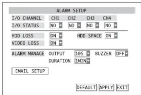
37 Submenu ALARM SETUP
3) In the line I/O STATUS, define for each alarm input in the list field if it is to be evaluated and define the contact type of the sensor connected:
OFF the input will be ignored
NO contact type NO (normally open)
NC contact type NC (normally closed)
Note: To trigger an alarm via an alarm input, the corresponding camera channel must be approved for recording (submenu RECORD/RECORD SETUP, line CHANNEL = ON, chapter 8.1).
For DMR-188 only:
For setting the camera channels 5-8, click NEXT. Then click PREV. to return to the previous menu page.
4) In the list field next to HDD LOSS, define if an alarm is to be triggered (ON) or not (OFF) when the hard disk is missing.
5) In the list field next to HDD SPACE, define if an alarm is to be triggered (ON) or not (OFF) when the hard disk is full.
6) In the list field next to VIDEO LOSS, define if an alarm is to be triggered (ON) or not (OFF) when there is no video signal.
Note: To trigger an alarm in case of video signal loss, the corresponding camera channel must be approved for recording! (Submenu RECORD/RECORD SETUP, line CHANNEL = ON, chapter 8.1)
7) In the item ALARM MANAGE in the list field next to DURATION, define the length of the video sequence (30S, 1MIN, 2MIN, 5MIN) to be recorded when an alarm has been triggered via an alarm input or via the internal motion detector.
8) In the list field next to OUTPUT, define the closing time of the relay (10S, 20S, 40S, 60S) at the alarm output ALARM (24) after alarm triggering or if response is not desired (OFF).
9) In the list field next to BUZZER, define the duration of the acoustic alarm signal (10S, 20S, 40S,
60S) in case of alarm triggering or if an acoustic alarm signal is not desired (OFF).
10)To send a message by e-mail in case of alarm and to activate this option, click the button EMAIL SETUP (for details see chapter below).
11)To reset all settings of this submenu to the factory settings, click the button DEFAULT.
12)To store the settings, click the button APPLY, then confirm the message inserted "Saved successfully!" by clicking the button OK.
13)To exit the submenu, click the button EXIT or the right mouse button or press the button MENU / ESC (7) or MENU (32).
10.2 Notification by e-mail
If the recorder is connected to a computer network via the jack LAN (23) and this network is connected to the Internet (13- chapter 14.1), in case of alarm, notification by e-mail to an address previously defined will be possible. As an attachment, the e-mail will contain an image file in JPG format showing a snapshot from the video signal of the camera channel triggering the alarm.
To configure the notification by e-mail:
1) After clicking the button EMAIL SETUP in the submenu ALARM/ALARM SETUP (fig. 37), the submenu EMAIL SETUP will appear (fig. 38).
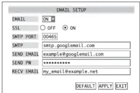
38 Submenu EMAIL SETUP
Example: transmission via "Google Mail"
2) In the list field next to EMAIL, define if the notification function is to be activated (ON) or not (OFF).
3) When the notification function has been activated, enter the parameters required for sending e-mails:
SSL encryption ON or OFF
SMTP PORT port number for transmission
SEND EMAIL address of sender
SEND PW password for access to the mail server for transmission
RECV EMAIL address of receiver
In chapter 6.2.3, a text input is described in detail. In addition to the input possibilities for the camera names listed there, special characters (fig. 39) will also be available.
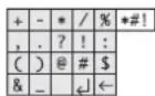
39 Set of special characters
4) To reset all settings of this submenu to the factory settings, click the button DEFAULT.
5) To store the settings, click the button APPLY, then confirm the message inserted "Saved successfully!" by clicking the button OK.
6) To exit the submenu, click the button EXIT or the right mouse button or press the button MENU / ESC (7) or MENU (32).
10.3 Motion detection
To configure the internal motion detector:
1) Activate the submenu DEVICES/ DEVICE MANAGEMENT (fig. 22) in the main menu (fig. 10).
2) Activate the submenu MOTION/MOTION DETECTION (fig. 40).
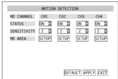
40 Submenu MOTION DETECTION
3) In the line STATUS, define in the list field for each camera channel if a movement detected is to be evaluated as an alarm (ON) or not (OFF).
Note: To trigger an alarm via motion detection, the corresponding camera channel must be approved for recording! (Submenu RECORD/ RECORD SETUP, line CHANNEL = ON, 8.1).
4) In the line SENSITIVITY in the list field, set the sensitivity for motion detection ( 1 = low, 4 = high) of each camera channel.
5) To define the coverage (MD AREA), click the button SETUP in the corresponding column. The camera image will be displayed with a grid of 13 × 10 fields over it (fig. 41). The red fields will mark the coverage for motion detection.
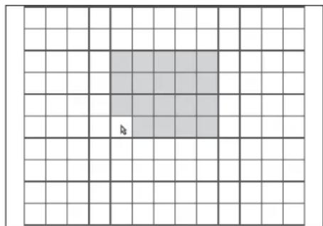
41 Motion detection grid
6) To change a field, click the field with the mouse pointer or select a field with the buttons and (8), (10) and (13) on the recorder or , , (29) on the remote control and confirm with the button SEL/EDIT (9) or SEL (33). To change large areas, keep the mouse button pressed and move the mouse pointer over the area.
To exit the area definition, click the right mouse button or press the button MENU/ESC (7) or MENU (32).
7) For DMR-188 only:
For setting the camera channels 5-8, click NEXT. Then click PREV. to return to the previous menu page.
8) To reset all settings of this submenu to the factory settings, click the button DEFAULT.
9) To store the settings, click the button APPLY, then confirm the message inserted "Saved successfully!" by clicking the button OK.
10)To exit the submenu, click the button EXIT or the right mouse button or press the button MENU / ESC (7) or MENU (32).
11 Camera Remote Control (PTZ)
It will be possible to remote-control suitable cameras from the recorder via a data bus connected to the terminals RS-485 (24). According to the features of the camera, remote control of movements such as pan and tilt, but also zoom, iris and speed will be possible. It will even be possible to store certain camera positions or settings and to start them automatically one after the other (CRUISE function, §§ chapters 11.3/11.4).
11.1 Configuring the control parameters
1) Activate the submenu DEVICES/ DEVICE MANAGEMENT (fig. 22) in the main menu (fig. 10).
2) Activate the menu PTZ/PTZ SETUP (fig. 42).
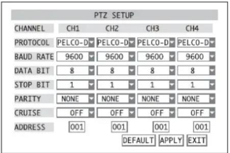
42Submenu PTZ SETUP
3) For each camera channel, the following parameters for communication can be entered:
PROTOCOL control protocol PELCO-D or PELCO-P
BAUD RATE data transmission rate 1200, ..., 9600 bauds
DATA BIT number of data bits 5, ..., 8
STOP BIT number of stop bits 1,2
PARITY parity NONE,ODD,EVEN,MARK(always1), SPACE (always0)
CRUISE ON = release camera for automatic surveillance tour (CRUISE function)
OFF = lock camera for automatic surveillance tour (CRUISE function)
ADDRESS address for individual control set on the camera
To change the parameters, select the desired value in the corresponding list field or enter the address (detailed description of an input chapter 6.2.3).
4) For DMR-188 only:
For setting the camera channels 5-8, click NEXT. Then click PREV. to return to the previous menu page.
5) To reset all settings of this submenu to the factory settings, click the button DEFAULT.
6) To store the settings, click the button APPLY, then confirm the message inserted "Saved successfully!" by clicking the button OK.
7) To exit the submenu, click the button EXIT or the right mouse button or press the button MENU/ESC (7) or MENU (32).
11.2 Controlling a camera
To control a camera during live surveillance:
1) Activate the full image display of the camera to be controlled [by double-clicking the image in the split screen or by pressing the corresponding button (5 or 27), chapter 7].
2) Activate the menu list (fig. 8) [click the right mouse button or press the button PTZ (16), SEL/EDIT (9) or SEL (33)].
3) Activate the list entry PTZ [click it or select it with the buttons and (8 or 29) and confirm with the button SEL/EDIT (9) or SEL (33)]. The window PTZ SETUP (fig. 43) will appear.

43 Window PTZ SETUP
4) To move the camera, click the direction arrows with the mouse pointer or select an arrow each with the buttons and (3), (4) and (5) on the recorder or , , , (29) on the remote control and release the corresponding movement with the button SEL/EDIT (9) or SEL (33).
5) Set the speed with the sliding control SLOW 31 FAST.
6) Click the button or respectively set the ZOOM, the FOCUS and the IRIS of the camera.
Note: It will depend on the features of the camera used which of the settings mentioned above can be remote-controlled.
7) To program the CRUISE function, click the button CRUISE SET. Details can be found in the chapter below.
8) To close the window, click the button EXIT or the right mouse button or press the button MENU/ESC (7) or MENU (32).
11.3 Configuring the CRUISE function
The CRUISE function will enable the recorder to incite the remote-controlled cameras to repeatedly perform a surveillance tour consisting of several programmed positions.
To define the positions:
1) Activate the window CRUISE SETUP (fig. 44) via the button CRUISE SET in the window PTZ SETUP (fig. 43).
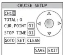
44 Window CRUISE SETUP
2) In the list field at the top on the left, select the camera channel to be set. The camera image will be displayed.
3) Click the arrows for direction to align the camera to the first surveillance target.
4) Enter the dwell time (in seconds) for this position in the input field STOP TIME.
5) Click the button SET to store the position. Next to TOTAL: you will find the number of positions already programmed.
6) In the input field CUR. POINT, the number of the next position to be programmed will be indicated. It can also be changed. If the button GOTO is clicked after entering the number of a position already stored, the camera will go to this position (detailed description of an input 3 chapter 6.2.3).
7) Go to the next position and store it until all desired positions have been programmed.
Note: To adapt the setting for zoom, focus or iris when defining the camera position, click the button SAVE after aligning the camera, confirm with OK, return to the window PTZ SETUP with EXIT and make the desired settings. Then activate the window CRUISE SETUP again with CRUISE SET and store the position with SET.
8) To delete all positions stored for the camera selected, click the button CLEAN.
9) When all positions for a camera have been defined, click the button SAVE to store.
10)For setting another camera, select it in the list field and store the positions like for the first camera.
11)Exit the window CRUISE SETUP via the button EXIT.
11.4 Activating/deactivating the CRUISE function
To start the CRUISE function:
1) Activate the menu list (fig. 8) [click the right mouse button or press the button PTZ (16), SEL / EDIT (9) or SEL (33)].
2) Activate the list entry START CRUISE [click it or select it with the buttons and (8 or 29) and confirm with the button SEL/EDIT (9) or SEL (33)]. The menu list will disappear and the automatic surveillance tour of the cameras will start.
Note: To include a camera in the surveillance tour, activate this function (CRUISE = ON) for the camera channel in the menu PTZ/PTZ SETUP (13 chapter 11.1).
To stop the CRUISE function:
1) Activate the menu list.
2) Activate the list entry STOP CRUISE. The menu list will disappear and the CRUISE function will stop.
GB 12 Password Protection
To protect the recorder against unauthorized change of menu settings, it will be possible to activate a two-stage password protection.
With the user password, it will be possible to access the submenu VIDEO SEARCH (K) chapter 9) to replay recordings or to export video files. Furthermore, remote control of the camera (K) chapter 11) will also be possible.
For all other settings in the menu, knowledge of the administrator password will be essential.
12.1 Configuring the password protection
To configure the passwords:
1) Activate the main menu (MAIN MENU, fig. 10).
2) Activate the submenu SYSTEM/SYSTEM SETUP (fig. 11).
3) Activate the submenu PASSWORD/ PASSWORD SETUP (fig. 45).
4) In the input field DEVICE ID, the preset value 000000 can usually be maintained as a device number. If the number is modified, you will have to remember it later when entering the password for operating the recorder.
5) In the list field next to PASSWORD ENABLE, define if a password protection is to be used (ON) or not (OFF).
6) If ON has been selected, enter a 6-digit number to be used as a user password in the input field next to USER PASSWORD (detailed description of an input 品 chapter 6.2.3). To confirm it, repeat this number next to CONFIRM.
Enter a 6-digit number to be used as an administrator password in the input field next to ADMIN PASSWORD. To confirm it, repeat this number next to CONFIRM and memorize it well!
7) To store the settings, click the button APPLY, then confirm the message inserted "Saved successfully!" by clicking the button OK.
8) To exit the submenu, click the button EXIT or the right mouse button or press the button MENU / ESC (7) or MENU (32).
12.2 Activating the password protection
To activate the password protection after exiting the setting menu:
1) Activate the menu list (fig. 8) [click the right mouse button or press the button PTZ (16), SEL/EDIT (9) or SEL (33)].
2) Activate the list entry MENU LOCK [click it or select it with the buttons and (8 or 29) and confirm with the button SEL / EDIT (9) or SEL (33)].
If the main menu, the submenu item VIDEO SEARCH or PTZ is activated, the window USER LOGIN (fig. 46) will appear.
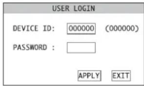
46 Window USER LOGIN
To gain access:
1) Enter the device number in the input field DEVICE ID: (detailed description of an input chapter 6.2.3). The preset number 000000 may be maintained if it has not been changed in the submenu PASSWORD/PASSWORD SETUP (fig. 45, chapter 12.1).
2) Enter the user password or administrator password in the input field PASSWORD:
3) Click the button APPLY. If the input is correct, access corresponding to the password will be granted.
If the input of the device number is incorrect, the message "Device number error!" will appear; if the password is incorrect, the message "Incorrect password!" will appear.
Confirm the message with OK, correct the input and accept it with APPLY.
Note: If the user password was entered to activate the submenu VIDEO SEARCH or PTZ, the message "Limited Authority!" will appear when another menu item is selected. To be able to enter the administrator password for access to the menu item desired, it will be necessary to exit the menu first and to select the item MENU LOCK from the menu list.
13 System Maintenance
In the submenu SYSTEM MAINTAIN, it will be possible to reset the recorder to the factory settings, to update the firmware (operating system of the recorder) or to restart the recorder manually or automatically at regular intervals.
1) Activate the main menu (MAIN MENU, fig. 10).
2) Activate the submenu SYSTEM/SYSTEM SETUP (fig. 11).
3) Activate the submenu MAINTAIN/SYSTEM MAINTAIN (fig. 47).
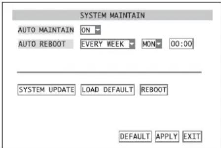
47 Submenu SYSTEM MAINTAIN
4) In the list field next to AUTO MAINTAIN, define if the recorder is to be restarted at regular intervals (ON) or not (OFF).
When the recorder is restarted regularly, it may be possible e. g. to detect a defective hard disk and to report the defect.
5) If ON has been selected, define next to AUTO REBOOT if the restart is to make EVERY DAY, EVERY WEEK or EVERY MONTH. Then define the time and, if required, the day or day of the week.
6) To restart the recorder manually, click the button REBOOT and click OK in the confirmation prompt appearing. To abort the process, click CANCEL.
7) To reset the recorder to the factory settings, click the button LOAD DEFAULT and click OK in the confirmation prompt pointing out that all settings made by the user will be lost. To abort the process, click CANCEL.
8) Via the button SYSTEM UPDATE, it will be possible to load a new operating software on the recorder from a storage medium connected to the USB port (22). Indication of the current system information will be described in the chapter below (13.1).
9) To reset all settings of this submenu to the factory settings, click the button DEFAULT.
10)To store the settings, click the button APPLY, then confirm the message inserted "Saved successfully!" by clicking the button OK.
11)To exit the submenu, click the button EXIT or click the right mouse button or press the button MENU/ESC(7)or MENU(32):
13.1 Indicating system information
To indicate the type of unit and the version of the operating software used and to indicate and change the MAC address of the recorder:
1) Activate the menu INFO/SYSTEM INFORMATION (fig. 48) from the menu SYSTEM/SYSTEM SETUP (fig. 11).
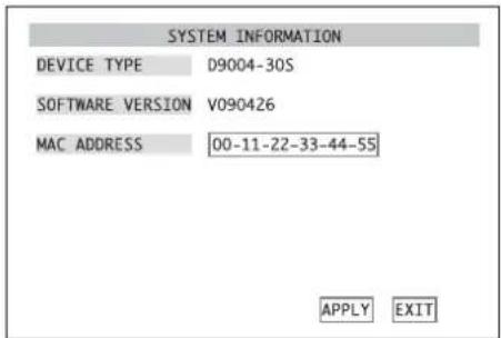
48 Submenu SYSTEM INFORMATION
2) Next to DEVICE TYPE, the internal device identification will be indicated; next to SOFTWARE VERSION, the version of the operating software used by the recorder will be indicated.
3) In the input field next to MAC ADDRESS (Media Access Control Address), the hardware address of the recorder (6 bytes in hexadecimal format) will be preset for unambiguous identification of the recorder in a computer network (Ethernet). It may be changed, if required (detailed description of an input chapter 6.2.3).
4) To store a MAC AD DRESS that has been changed, click the button APPLY, then confirm the message inserted "Saved successfully!" by clicking the button OK.
(5) To exit the submenu, click the button EXIT or the right mouse button or press the button MENU / ESC (7) or MENU (32).
14 Remote Access via Computer Network
Via its connection jack LAN (23), it will be possible to connect the video recorder to an individual computer, to a local computer network or, e.g. via a router, to the Internet. For correct configuration, comprehensive knowledge of computer network technology will be essential.
14.1 Setting up a network connection
1) Activate the main menu (MAIN MENU, fig. 10).
2) Activate the submenu NETWORK/NETWORK SETUP (fig. 49).
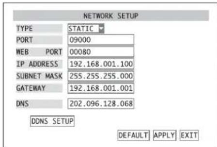
49 Submenu NETWORK SETUP
3) For TYPE, select the type of network connection: DHCP Dynamic Host Configuration Protocol a DHCP server (e.g. a router) will assign the network configuration to the recorder
STATIC the network configuration (IP ADDRESS, SUBNET MASK, GATEWAY) will be manually defined in the recorder
PPPOE Point-to-Point Protocol over Ethernet e.g.for a direct Internet connection viaDSL modem; the access data (PPPOE NAME, PASSWORD) will be made available by the Internet service provider
4) Enter the parameters PORT, WEB PORT, IP ADDRESS, SUBNET MASK, GATEWAY, DNS) required for the type of network connection selected (detailed description of an input chapter 6.2.3).
5) For remote access, the IP address of the recorder must be known. However, many Internet providers change it each time a connection is made (dynamic IP address). To solve this problem, use a DDNS server, i.e. a network service offered by several service providers. After registration with a service provider, you will select a definite subdomain for addressing the recorder and a user name and a password for access. If the DDNS service provider "dynds" is used, the subdomain may be, for example, "example.dynds.org".
Use of this service will usually be configured in the router connecting the recorder to the Internet, but will also be possible with the recorder.
Each time a connection is made, the router or recorder will send its current IP address to the DDNS server which will store it and accordingly route any queries made to the subdomain to the recorder.
To configure the recorder for using a DDNS server, click the button DDNS SETUP in the sub menu NETWORK SETUP. The submenu DDNS SETUP, fig. 50 will appear. In the list field next to DDNS, define if the DDNS function of the recorder is to be used (ON) or not (OFF). Select the service provider in the list field next to SERVER. In the input fields, enter the parameters defined (HOST NAME, USERNAME and PASSWORD) during registration with the service provider.
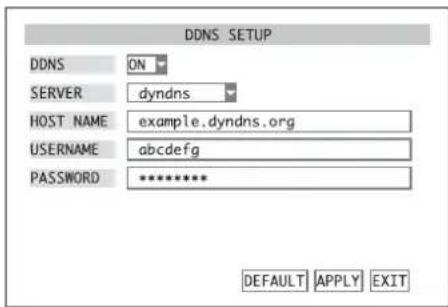
50 Submenu DDNS SETUP Example: dynamic IP via "dyndns"
6) To reset all settings of this submenu to the factory settings, click the button DEFAULT.
7) To store the settings, click the button APPLY, then confirm the message inserted "Saved successfully!" by clicking the button OK.
Note: Changes of the network parameters will not become effective until the recorder has been restarted.
8) To exit the menu, click the button EXIT or the right mouse button or press the button MENU / ESC (7) or MENU (32): If changes have been made, a message will appear announcing the restart of the recorder. Click the button OK to confirm.
14.2 Remote control via the programs Windows Internet Explorer or 9D-VIEWER
Via the network, the programs Windows Internet Explorer (IE) or the 9D-VIEWER provided will be able to access the recorder in order to display live images of the cameras or to replay recordings regardless of the view selected on the recorder. Furthermore, it will be possible to change settings of the recorder.
When the first connection is made via the IE, after entering the IP address of the recorder (or the public IP address of the router to which the recorder has been connected) in the address bar, the IE will load an extension required (ActiveX control element) from the recorder and will install it on the computer. If necessary, relax the security settings of the IE to allow this process.
As an alternative to operation via the IE, use the program 9D-VIEWER. This program is supplied on a CD with the recorder and offers the same possibilities as operation via the IE. To install, start the program "D9-PCviewer-en.exe" and follow the instructions on the screen. After installation, start the program file "D9-VIEWER.exe".
After starting or after making the connection, the window "USER LOGIN" (fig. 51) will appear.
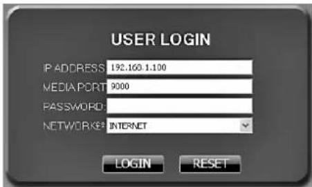
51 Window "USER LOGIN" for remote access
1) For "IP ADDRESS", enter the IP address of the recorder (already entered in the IE) or the public IP address of the router to which the recorder has been connected.
2) For "MEDIA PORT", enter the port number entered in the input field PORT in the submenu NETWORK SETUP of the recorder (K59 chapter 14.1, fig. 49).

3) For "password", enter the user password or administrator password if a password protection for network access has been configured (us chapter 14.2.3.5).
Note: The password protection for network access is independent of the password protection for local operation of the recorder described in chapter 12.
4) For "NETWORK", select the type of network connection: "LAN" (local network) or "INTERNET".
5) Click the button "LogIn". If the login data have been correctly entered and if the network connection is correct, the view "LIVE" (fig. 52) will be shown and remote access to the recorder will be possible.
Otherwise, "Login Failed" will appear in the window on the bottom on the left; in this case, check the network connection and the inputs, correct it, if required and click "LOGIN" again.
It will be possible to switch over the different views (LIVE/REPLAY/SETUP/LOGOUT)viathetabsin the upper part.
Note: If the message "Other User Configuring ..." appears when a function in the D9-Viewer or IE is activated, this function will be blocked by the fact that the setting menu or the camera control (PTZ) is currently activated on the recorder. After exiting the menu or the camera control on the recorder, this function will be available again for remote access.
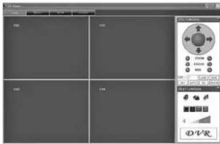
52View LIVE
14.2.1 View "LIVE"
On the left, the current camera images will be shown. When double-clicking a camera image, it will be possible to switch to full image display and back. It will also be possible to switch between full image display, display divided in 4 images, display divided in 9 images and display divided in 16 images via the buttons窗口 area "PLAY CONTROL" (fig. 53).
When clicking the icon "OPEN WINDOW", it will be possible to generally switch on or off the display of the camera images. This will also be possible via the options "OPEN ALL" and "CLOSE ALL" in the list which will appear when clicking a camera image with the right mouse button. Alternatively, the display for the camera channels can be controlled individually when the corresponding display field is clicked with the right mouse button and when in the list appearing "OPEN WINDOW" is selected for activating the camera image or "CLOSE" is selected for deactivating it.
Via the icons, it will be possible to set the volume for the audio signal of the camera channel currently selected (marked with a red frame in a display of multiple channels). To mute the sound, click the speaker icon.
14.2.1.1 Storing snapshots
If the icon "CAPTURE" is clicked, a snapshot of the image currently selected (marked with a red frame in a multiple-channel display) will be stored in Windows bitmap format (*.BMP). It will be stored in a subdirectory "Capture", separated according to channels, in the path defined in the input field "FILE SAVE PATH" under "SETUP / SETTING" chapter 14.2.3.5).
14.2.1.2 Recording video sequences
Clicking the icon "RECORD" will start and stop recording of all camera channels selected for display, i.e. not deactivated with "CLOSE". Regardless of the recording activity of the recorder, a recording of the live images transmitted will be created on the computer.
Alternatively, the display for the camera channels can be controlled individually when the corresponding camera image is clicked with the right mouse button and when in the list appearing, "START RECORD" is selected for starting the recording or "STOP" is selected for stopping it.
During recording, the icon will be indicated in the corresponding image. Contrary to the recorder, a recording will be made regardless of the approval for recording of the camera channel in the recorder or of the presence of a video signal.
The video files will be compressed, like in the recorder, according to the standard H.264 (*.264 format). They will be stored in a subdirectory "Record", separated according to month of recording and channels, in the path defined in the input field "FILE SAVE PATH" under "SETUP / SETTING" (3 chapter 14.2.3.5).
14.2.1.3 Camera control (PTZ CONTROL)
Similar to the description in chapter 11, it will be possible to remote-control suitable cameras in the window area "PTZ CONTROL" (fig. 54).
To control the movement of the camera selected, click the arrows. According to the features of the camera, ZOOM, FOCUS and IRIS will be remote-controlled by clicking 品
After making the settings, click the button "SET" to store a camera position.
To go to a position already stored, enter the position number in the field next to "CUR" and click "GOTO".
Click "CLS" to delete all positions stored.
Click "SAVE" to transmit all positions programmed here to the recorder and store them there.
Click "LOAD" to reload the positions stored on the computer.
Click "CRUISE" to start and stop the surveillance tour where all camera positions programmed will be automatically approached repeatedly (133 chapter 11.4).
14.2.2 View "REPLAY"
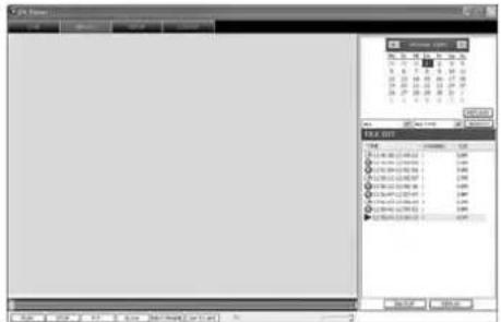
55.View REPLAY
Via the view "REPLAY" (fig. 55), it will be possible to replay recordings stored on the hard disk of the recorder (not recordings made in the view "LIVE" with the function "RECORD", see chapter 14.2.1.2).
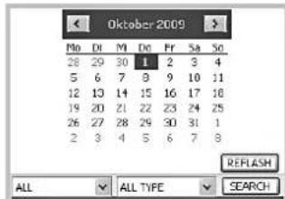
56. View REPLAY, selecting recordings
1) Via the calendar (fig. 56), select the day when the recording was made (days when recordings were made will be indicated in bold).
2) In the left list field below the calendar, define if recordings of all camera channels (ALL) or of a particular channel only (1, 2, ...) are to be listed.
3) In the right list field below the calendar, define if recordings of both types (ALL TYPE), recordings triggered by alarm only (ALARM) or recordings triggered manually or time-controlled of the type "normal" (COMMON) are to be listed.
4) Click the button "SEARCH". The video files recorded on the day selected will be listed (fig. 57). For each file, the type of recording (normal recording, alarm recording), the recording time, the number of the camera channel and the file size will be indicated.
To update the list of recordings for the day selected, click the button "REFLASH" (fig. 56).
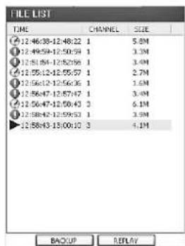
View REPLAY, FILE LIST
5) Select a video file from the list and start the replay with "REPLAY".
6) Click "BACKUP" to store the video file selected on the computer. The video files stored this way will be compressed, like in the recorder, according to the standard H.264 (.264 format). They will be stored in a subdirectory "Backup" in the path defined in the input field "FILE SAVE PATH" under "SETUP/SETTING" (Chapter 14.2.3.5).
14.2.2.1 Replay control
Similar to the description in chapter 9, it will be possible to control the replay of a video file in the lower part of the window (fig. 58). The vertical box (green) will indicate the current replay position within a video file and can also be displaced with the mouse to select a particular point of time. The horizontal bar (blue) behind it will indicate the download process of the file from the recorder. With large files, delays may occur in operation while the file is still being loaded.
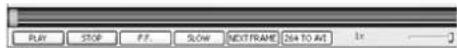
View REPLAY, replay control
The explanation of the buttons:
PAUSE to interrupt the replay,
indication:"PAUSE"
PLAY to start or continue the replay indication: "1x"
F.F. to replay at 2-fold, 4-fold
8-fold or 16-fold speed
(click repeatedly)
indications: "2x", "4x", "8x", "16x"
SLOW to replay in slow motion at
1/2, 1/4, 1/8 or 1/16 of the normal
speed (click repeatedly)
indications:“-2x”,“-4x”
“-8x”,“-16x”
NEXT FRAME to interrupt the replay and to
continue in frames
indication:"Step"
To adjust the volume of audio replay, use the "sliding control" on the right.
14.2.2.2 Converting video files
The files recorded from the video recorder and the video files recorded on the computer via the function "RECORD" in the view "LIVE" (13 chapter 14.2.1.2) will be compressed according to the standard H.264. To replay them with programs not yet supporting this standard, store the files in AVI video format.
For this purpose, files from the recorder must be downloaded to the computer first by means of the button "BACKUP" (fig. 57) and stored there.
For converting:
1) Click "264 TO AVI" (fig. 58). The window "Avi-Convert" (fig. 59) will open.
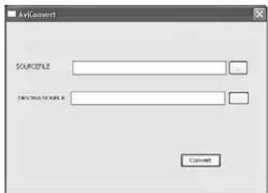
59 Conversion to AVI format
2) In the line "SOURCEFILE", enter the path of the file to be converted or click the button "... and search for the file. The files from the recorder will be in the directory "Backup", the files recorded on the computer in the directory "Record" in the path defined under "SETUP / SETTING", "FILE SAVE PATH" (F8 chapter 14.2.3.5).
3) In the line "DESTINATIONFILE", enter the path and the name of the target file (with the extension .AVI) or click the button "...", search for the path and enter the file name.
4) Click "Convert" to start converting. After successful conversion, the message "Conversion finished!" will appear.
5) For further conversions, repeat steps 2-4. Then close the window "AviConvert".
14.2.3.View“SETUP”
Via the view "SETUP", it will be possible to retrieve information concerning the recorder, to change settings of the recorder and to make settings for remote access.
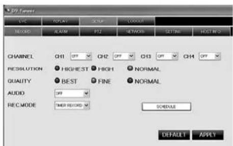
14.2.3.1 SETUP/RECORD
60View SETUP/RECORD
The settings made in the view "SETUP / RECORD" (fig. 60) will affect the submenu "RECORD SETUP" in the recorder (81).
The following definitions will apply:
for "RESOLUTION" (not for DMR-188)
HIGHEST = D1 (in the recorder menu)
HIGH= HD1
NORMAL = CIF
for "QUALITY"
BEST = BEST
FINE =GOOD
NORMAL = NORMAL
for "AUDIO"
ON = ENABLE
OFF = DISABLE
for "REC.MODE"
TIMER RECORD = TIME SCHEDULE RECORD
POWER UP = ALWAYS
For DMR-188 only:
For setting the camera channels 5-8, click the
button "NEXT". Then click "PREVIOUS" to return to the previous view.
If "TIMER RECORD" has been selected, the recording schedule (fig. 61) will open via the button "SCHEDULE".
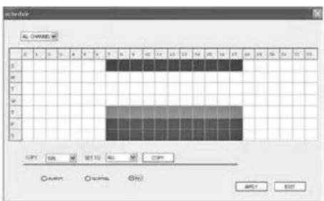
(6)View SETUP/RECORD/SCHEDULE
As described in chapter 8.2.3, it will be possible to define the recording schedule for the camera channels here.
The following definitions will apply: "NORMAL" = GENERAL and "NO" = NO RECORD.
If you click "APPLY", the recorder will accept the changes; if you click "EXIT", the window will be closed. After successful transmission, the message "Configure success!" will appear.

14.2.3.2 SETUP/ALARM
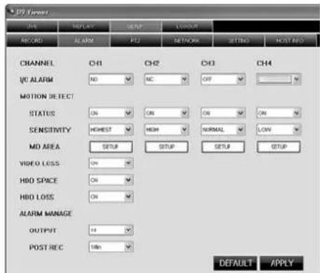
62ViewSETUP/ALAR
The settings made in the view "SETUP/ALARM" (fig. 62) will affect the submenu "ALARM SETUP" (13 chapter 10.1) and "MOTION DETECTION" (14 chapter 10.3) of the recorder. The following definitions will apply: "I/O ALARM" = I/O STATUS in the recorder menu, "POST REC" = DURATION and for "OUTPUT" = "0" = OFF.
For "MOTION DETECT" under "SENSITIVITY":
LOW = 1 (in the recorder menu)
NORMAL = 2
HIGH = 3
HIGHEST = 4
In the window inserted via the button "SETUP", the coverage of motion detection for each channel will be defined, like on the recorder, by clicking the grid fields (red marking) [the outermost fields are not part of it]. However, the camera image will not be visible (fig. 63).
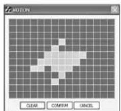
(63)View SETUP/ALARM/MOTION
Click "CLEAR" to reset all fields, "CONFIRM" to accept the changes made, "CANCEL" to abort them.
For DMR-188 only:
For setting the camera channels 5 - 8, click the button "NEXT". Then click "PREVIOUS" to return to the previous view.
Via the button "DEFAULT", the factory settings will be displayed. If the button "APPLY" is clicked, any changes made in the view "SETUP/ALARM" will be transmitted to the recorder. After successful transmission, the message "Configure success!" will appear.
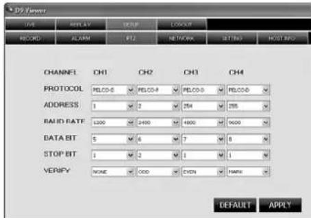
(64)View SETUP/PTZ
The settings made in the view "SETUP/PTZ" (fig. 64) will affect the menu for setting the camera remote control PTZ SETUP in the recorder (13 chapter 11.1). "VERIFY" corresponds to the term PARITY in the menu of the recorder. The option "CRUISE = ON / OFF" is not available here; it must be set directly on the recorder.
For DMR-188 only:
For setting the camera channels 5-8, click the button "NEXT". Then click "PREVIOUS" to return to the previous view.
Via the button "DEFAULT", the factory settings will be displayed. If the button "APPLY" is clicked, any changes made in the view "SETUP/PTZ" will be transmitted to the recorder. After successful transmission, the message "Configure success!" will appear.
14.2.3.4 SETUP/NETWORK
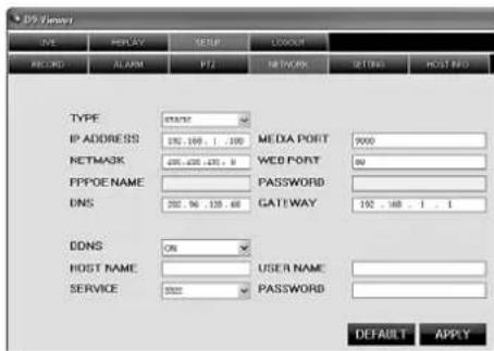
65 View SETUP/NETWORK
The settings made in the view "SETUP/NETWORK" (fig. 65) will affect the submenu for setting the "NETWORK SETUP in the recorder (133 chapter 14.1).
Via the button "DEFAULT", the factory settings will be displayed. If the button "APPLY" is clicked, any changes made in the view "SETUP/NETWORK" will be transmitted to the recorder. After successful transmission, the message "Configure success!" will appear.
Note: Changes of network parameters will not become effective until the recorder is restarted. Please note: When these parameters are changed thoughtlessly, remote access may no longer be possible so that readjustment of the parameters will have to be made on the recorder itself.
14.2.3.5 SETUP/SETTING
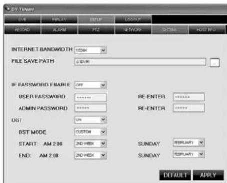
6 View SETUP/SETTING
In the view "SETUP/SETTING" (fig. 66), on the one hand, you will be able to change the automatic switchover between daylight saving time and standard time of the recorder, on the other hand, settings for remote access will be possible.
Via "INTERNET BANDWIDTH", it will be possible to set the bandwidth for video transmission via the Internet.
"FILE SAVE PATH" is the directory path where the files of the functions "CAPTURE" (E chapter 14.2.1.1), "RECORD" (E chapter 14.2.1.2) and "BACKUP" (E chapter 14.2.2) will be stored.
With "IE PASSWORD ENABLE" it will be possible to define if the password protection for remote access is to be activated (ON) or not (OFF). This password protection is independent of the password protection on the recorder (13 chapter 12) and only applies to remote access. If "ON" has been selected, enter the desired user password in the field "USER PASSWORD" and, for security reasons, repeat the password in the field next to it. In the field "ADMIN PASSWORD", enter the desired administrator password and, for security reasons, repeat the password in the field next to it. Memorize the password well; remote configuration will not be possible if you do not remember it!
The password protection will not become effective until a new connection has been made to the recorder(LOGOUT/LOGIN, chapter 14.2.4). If you enter the defined user password in the field "password" when logging in (window "USER Login", fig. 51), only the views "LIVE", "REPLAY" and "LOGOUT" will be available. For the remaining functions of remote access, input of the administrator password will be essential.
The parameters to be set under "DST" refer to automatic switchover of the recorder between daylight saving time and standard time ( chapter 6.2.4).
Via the button "DEFAULT", the factory settings will be displayed. If the button "APPLY" is clicked, any changes made in the view "SETUP/SETTING" will be transmitted to the recorder. After successful transmission, the message "Configure success!" will appear.
14.2.3.6 SETUP/ HOST INFO
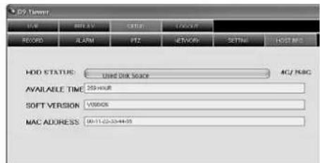
67 View SETUP/ HOST INFO
In the view "SETUP/HOSTINFO"(fig. 67), information concerning the recorder will be indicated which will also be available in the submenus "HDD MANAGEMENT" (3 chapter 8.1.1) and "SYSTEM INFORMATION" (4 chapter 13.1) of the recorder.
HDD STATUS = storage space used of the hard disk (e.g. 4G / 250G for a 250 GB hard disk with 4 GB used)
SOFT VERSION = SOFTWARE VERSION
AVAILABLE TIME = USEABLE REC TIME
MAC ADDRESS = device address (Media
Access Control Address)
14.2.4 View LOGOUT
When switching over to the view "LOGOUT", data communication with the recorder will be terminated. The window "USER LOGIN", fig. 51 for login will appear.
14.3 Remote access via mobile phone
Similar to remote control via a computer, remote control of the recorder via a suitable web-enabled mobile phone (UMTS or WLAN) will be possible. For this purpose, connect the recorder to the LAN / Internet (13) chapters 14 / 14.1) and install a special program on the mobile phone. For mobile phones with the operating systems "Windows Mobile" and "Symbian", programs are supplied on the CD.
To install the programs:
1) According to the operating system of the mobile phone, copy the file from the corresponding directory of the CD via a computer to the memory card of the mobile phone (e.g. via data cable).
2) Open the copied file in the mobile phone and install the program included in the file in the memory of the phone.
To configure access on the recorder:
1) Activate the menu DE VICES/ DEVICE MANAGEMENT (fig. 22) in the main menu (fig. 10).
2) Activate the menu MOBILE (fig. 68).
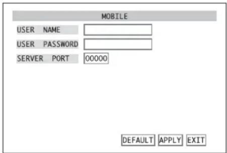
68 Submenu MOBILE
3) In the input field next to USER NAME, enter a user name. The user name defined here must also be entered in the program installed on the mobile phone.
4) In the input field next to USER PASSWORD, enter a password for access. The password defined here must also be entered in the program installed on the mobile phone.
5) In the input field next to SERVER PORT, enter the number of the server port. This port is used for mobile access only. Select a number between 1024 and 65535; however, it must not be identical to a port number already entered in the submenu NETWORK/NETWORK SETUP chapter 14.1, fig 49). Also set the server port defined here in the program installed on the mobile phone.
6) To reset all settings of this submenu to the factory settings, click the button DEFAULT.
7) To store the settings, click the button APPLY, then confirm the message inserted "Saved successfully!" by clicking the button OK.
8) To exit the submenu, click the button EXIT or the right mouse button or press the button MENU / ESC (7) or MENU (32).
Contrary to remote access via a computer, you will not be able to display several camera channels at the same time on the mobile phone. The display speed will depend on the speed of your Internet connection.
15 Specifications
Video standard: PAL/NTSC selectable
Video inputs
DMR-180 / DMR-184: . . . 4 BNC
DMR-188: 8 BNC
Video outputs: 2 BNC, 1 VGA
Audio inputs
DMR-180 / DMR-184: . . . 4 RCA
DMR-188: 1 RCA
Audio outputs
DMR-180 / DMR-184: .2 RCA
DMR-188: 1 RCA
Image resolution for display (pixels hor. × vert.)
PAL: 704×576
NTSC: 704×480
Image resolution for recording (pixels hor. × vert.)
DMR-180/DMR-184:
| PAL | NTSC | |
| D1 | 704 × 576 | 704 × 480 |
| HD1 | 704 × 288 | 704 × 240 |
| CIF | 352 × 288 | 352 × 240 |
DMR-188:
| PAL | NTSC | |
| CIF | 352 × 288 | 352 × 240 |
Video compression: .H.264
Recording rate (frames per second)
DMR-180/DMR-184:
| PAL | NTSC | |
| D1 | 25 fps | 30 fps |
| HD1 | 50 fps | 60 fps |
| CIF | 100 fps | 120 fps |
DMR-188:
| PAL | NTSC | |
| CIF | 200 fps | 240 fps |
Alarm inputs
DMR-180 / DMR-184: . . . 4, NO / NC contact,
selectable
DMR-188: 8, NO / NC contact,
selectable
Alarm output: 1 NO contact,
24V/500mAmax.
Camera remote control: . . PELCO-P / PELCO-D
protocol via RS-485
Interfaces: 2 USB 2.0 for storage
medium and mouse,
1 RJ45 Ethernet for
computer network
Power supply via power supply unit provided
DMR-180 / DMR-184: . . . 12 V, 5 A max.
DMR-188: 12 V, 3 A max.
Power consumption of the recorder
(without hard disk) .0.8-1.3 A at 12 V=
Dimensions: 300 × 55 × 225 mm
Weight
DMR-180: 4 kg
DMR-184: 3.5 kg
DMR-188: 3.7 kg
Subject to technical modification.
F Table des matieres
FWD (13) ou (31) => 2X, >> 4X, >> 8X
REW (10) ou (31) = <<2X, <<4X, <<8X
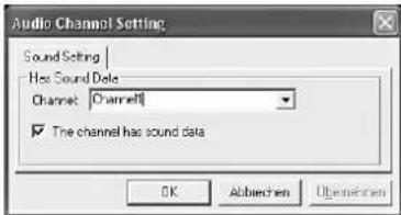
35"Audio Channel Setting
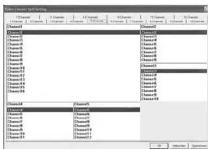
36"Video Channel Split Setting - 5 Channels
NC contact d'ouverture (normally closed)
ON = ENABLE OFF = DISABLE
Pour "REC.MODE"
TIMER RECORD = TIME SCHEDULE RECORD
POWER UP = ALWAYS
MAC ADDRESS = adress appeareil (Media Access Control Address)
14.2.4 Visualisation "LOGOUT"
| PAL | NTSC | |
| CIF | 352×288 | 352×240 |
Compression video: . . . . . H.264
5.6 Rete per computer (LAN)
FWD (13) o (31) = >>2X, >>4X, >>8X
REW (10) o (31) = <<2X, <<4X, <<8X
9.2.1 Aprire i file video
9.2.3 Rielaborare file video
9.2.3.4 Cancellare i file video
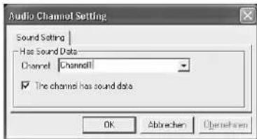
35"Audio Channel Setting
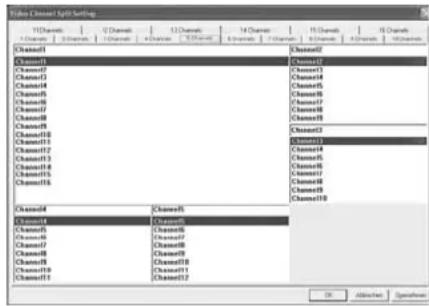
36"Video Channel Split Setting - 5 Channels
NC contatto di riposo NC (normally closed)
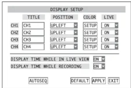
(14) Submenu DISPLAY SETUP
E
PAUSE II (11) III (31) = PAUSE, FRAME PLAY ▷ (12) ▷ (31) = PLAY
FWD (13) o (31) => 2X, >> 4X, >> 8X
REW (10) o (31) = <<2X, <<4X, <<8X
STOP 4) o (31=abortar la reproduccion
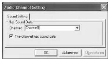
35"Audio Channel Setting
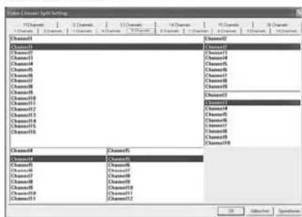
36"Video Channel Split Setting - 5 Channels
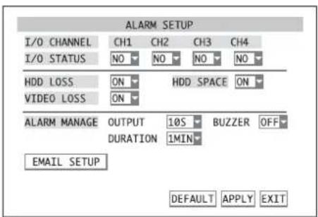
37 Submenu ALARM SETUP
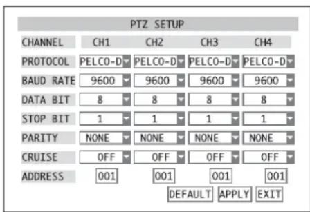
42 Submenu PTZ SETUP
14.2.2 Vista "REPLAY"
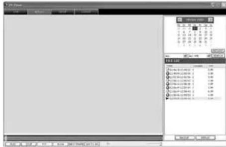
(55)Vista REPLAY
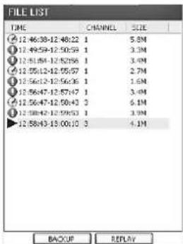
57 Vista REPLAY, FILE LIST
| PAL | NTSC | |
| CIF | 352×288 | 352×240 |
Compresion video: .H.264
Tasa de grabacion (frames por世代)
DMR-180/DMR-184:
| PAL | NTSC | |
| D1 | 25 fps | 30 fps |
| HD1 | 50 fps | 60 fps |
| CIF | 100 fps | 120 fps |