
Mobi Supreme - Exercise bike Klarfit - Free user manual and instructions
Find the device manual for free Mobi Supreme Klarfit in PDF.
| Product type | Exercise bike |
| Brand | Klarfit |
| Model | Mobi Supreme |
| Intended use | Home use |
| Maximum user weight | 120 kg |
| Standards | EN957, CE, RoHS |
| Power supply | AC adapter (6V DC, 1A) |
| Resistance levels | 8 levels (1-8) |
| Training programs | Manual P1, Automatic P2-P7, Pulse control P8-P11 |
| Display | Speed, RPM, distance, calories, pulse, resistance, watt, age |
| Pulse sensors | Hand grip pulse sensors |
| Recovery test | Pulse Recovery function (F1.0 to F6.0) |
| Dimensions (L x W x H) | Approx. 100 x 50 x 130 cm |
| Net weight | Approx. 30 kg |
| Materials | Steel frame, foam handles |
| Safety | Emergency stop (start/stop), max weight 120 kg, conforms to EN957 |
| Maintenance | Check screws and fasteners before each use, do not repair yourself |
| Cleaning | Only with a dry cloth |
| Assembly | Requires assembly, screws and tools included, detailed manual included |
| Spare parts | List provided in the manual, use only recommended accessories |
| Recycling | Compliant with WEEE, do not dispose of with household waste |
Frequently Asked Questions - Mobi Supreme Klarfit
User questions about Mobi Supreme Klarfit
0 question about this device. Answer the ones you know or ask your own.
Ask a new question about this device
Download the instructions for your Exercise bike in PDF format for free! Find your manual Mobi Supreme - Klarfit and take your electronic device back in hand. On this page are published all the documents necessary for the use of your device. Mobi Supreme by Klarfit.
USER MANUAL Mobi Supreme Klarfit
natural_image
Line drawing of an outdoor exercise bike with adjustable arms and wheels (no text or symbols)other
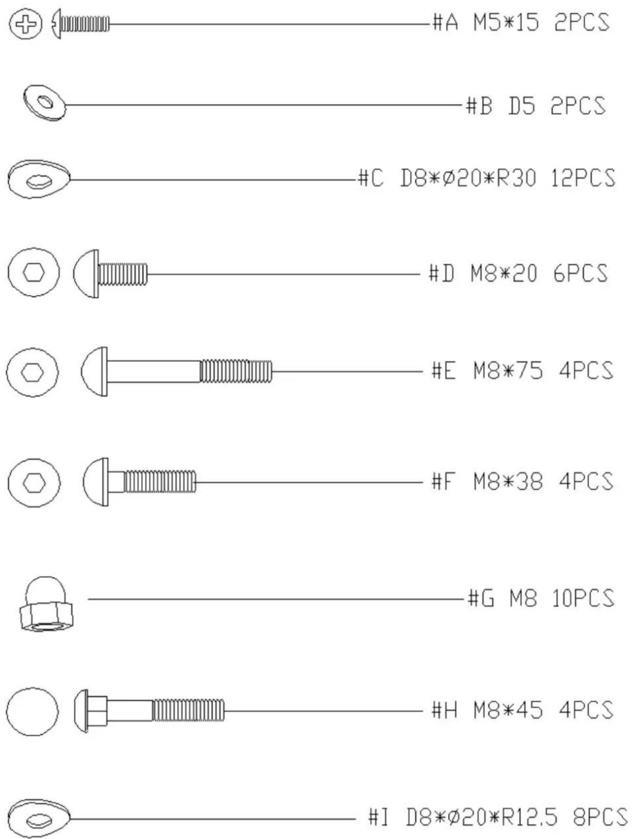
| Component | Size | PCS | | --------- | ---- | --- | | #A | 2 | 15 | | #B | 2 | 5 | | #C | 12 | 20 | | #D | 6 | 20 | | #E | 4 | 75 | | #F | 4 | 38 | | #G | 10 | 8 | | #H | 4 | 45 | | #I | 8 | 20 |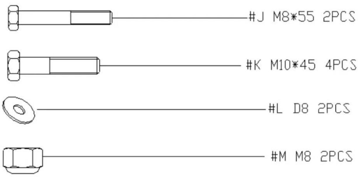

natural_image
Pure mechanical component outline diagram without any text, numbers, or symbolsS(17-17-19)-2

natural_image
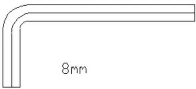
Simple line drawing of a double-ended wrench (no text or symbols)S(13-14)


Aufbau - Schritt 1
Aufbau - Schritt 2
Aufbau - Schritt 4
Aufbau - Schritt 7
Aufbau - Schritt 8
natural_image
Four pixelated black-and-white grid patterns, no text or symbols presentnatural_image
Symbol of a trash bin crossed with a diagonal line, no text or numbers presentCongratulations on purchasing this equipment. Please read this manual carefully and take care of the following hints to avoid damages.
Warning and Safety Instructions
- Read this manual carefully before setting up and using the device. A safe and effective use of the device can only be achieved if the device is properly constructed, maintained and used. Make sure that all persons using this device are aware of the warnings and safety instructions.
- Before you start training with this device, you should consult a doctor in order to check for physical or health limitations that may prevent the safe and efficient handling of this training device. If you are taking medications that affect blood pressure, heart rate or cholesterol levels, the consultation of a doctor before training is absolutely necessary.
- Pay attention to your body's signals. Incorrect or excessive training can be harmful. Stop training immediately if you notice the following symptoms: pain / tightness in the chest, irregular heartbeat, extreme shortness of breath, signs of light-headedness, dizziness or nausea. If you experience any of these symptoms, you should consult a doctor before you continue training.
- This device is not intended to be used by people with reduced physical, sensory or mental abilities or by persons (including children) who lack experience and / or knowledge, unless they are supervised by a person responsible for their safety or receive instruction in how the device is to be used. Children should be supervised to ensure that they do not play with the appliance.
- Set the device on a dry, level surface.
- Make sure all screws and fasteners are properly and securely tightened before each workout.
- Reliability can only be ensured if the unit is regularly maintained and inspected for any damage or signs of wear.
- Use the device only as intended. If you should find defective components when building or checking the unit, or you notice an unusual noise from the device during exercise, stop training immediately. Only resume use of the device after the problem is identified and resolved.
- Wear appropriate clothing when using this equipment. Avoid loose clothing that could become caught on the device and that may limit your freedom of movement.
- The device has been tested and certified to EN957 and has been approved for home use. The maximum user weight should not exceed 120kg.
- The device is not suitable for therapeutic use.
- Be careful when lifting or moving the appliance. Use back-friendly lifting techniques and get support when moving the unit.
- Do not expose this device to rain.
- Do not place objects filled with liquids, such as vases, on this unit.
- Use only the recommended accessories.
- Do not attempt to repair this unit yourself.
- For servicing, refer to qualified service personnel.
- Clean the device only with a dry cloth.
- Do not place open flame sources, such as burning candles, on the device.
- Keep small objects (for example, screws and other assembly materials, memory cards) and packaging parts out of reach of children so that they can not be swallowed. Do not let small children play with film. Risk of suffocation.
- Please keep the original packaging. In order to ensure adequate protection during transport of the unit, pack it in its original packaging.
Construction
Exploded drawing
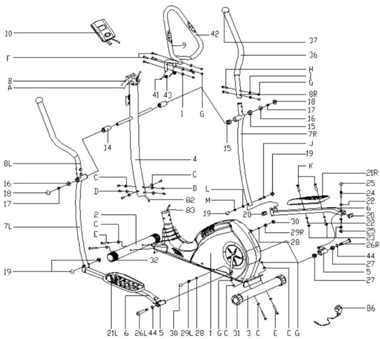
List of items
| Main frame | 1 31 End | cap | |
| Support front | 2 32 End | cap | |
| Support back | 3 | ||
| Handle holder | 4 36 Foam grip | ||
| Rod joint | 5 37 Cap | ||
| Pedal rod | 6 | ||
| Flywheel rod | 7 41 Pulse cable | ||
| Handle | 8 42 Pull | handle foam | |
| Handle support | 9 43 End | cap | |
| Computer | 10 44 Corrugated disc | ||
| Sleeve | 14 82 Sensor cable | ||
| Axle sleeve (1) | 15 83 Motor cable | ||
| Flat disc 8.2x32x2 | 16 | ||
| Hexagon bolt M8x15 | 17 86 Adapter | ||
| Round cap S14 | 18 | ||
| Round cap | 19 A Philips screw | M5x15 | |
| Round cap | 20 B Grooved disc | D5 | |
| Pedal | 21 C Grooved disc | bent D8xΦ20xR30 | |
| Disc | 22 D Hexagon bolt | M8x20 | |
| Safety bolt | 23 E Hexagon bolt | M8x75 | |
| Hexagon bolt M10x50 | 24 F Screw M8x38 | ||
| Round cap S17 | 25 G Cap nut | ||
| Crank bolt | 26 H Screw M8x45 | ||
| Axle sleeve (2) | 27 I Grooved disc | bent D8xΦ20xR12,5 | |
| Spring washer D13 | 28 J Hexagon bolt | M8x55 | |
| Safety bolt B0.5x20 | 29 K Hexagon bolt | M10x45 | |
| Round cap S19 | 30 L Grooved disc | D8 | |
| M | Safety bolt M8 | ||
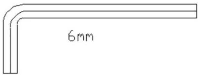
Screws and Tools


natural_image
Pure mechanical component outline diagram without any text, numbers, or symbolsS(17-17-19)-2

natural_image
Simple line drawing of a double-ended wrench (no text or symbols)S(13-14)


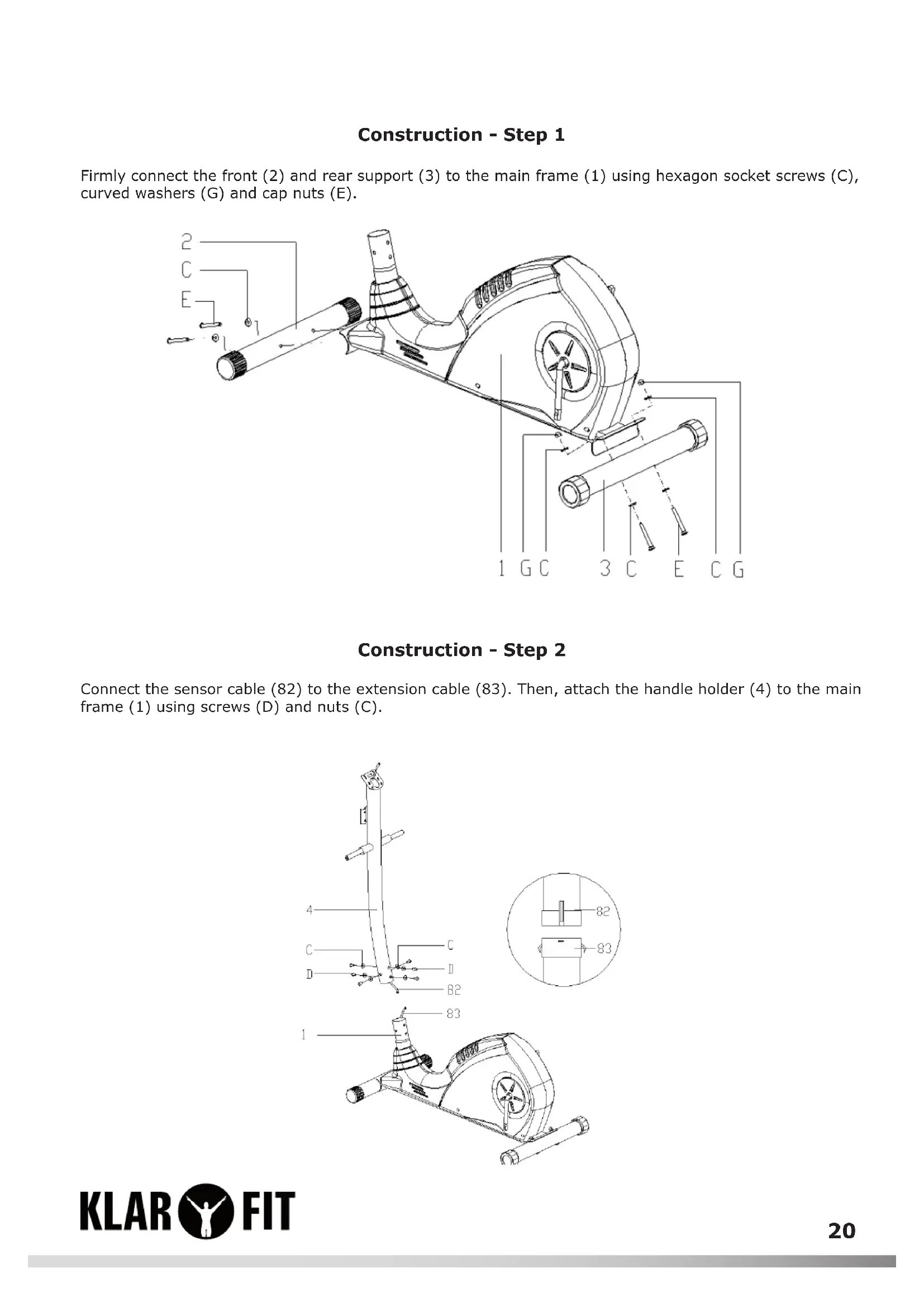
Construction - Step 1
Firmly connect the front (2) and rear support (3) to the main frame (1) using hexagon socket screws (C), curved washers (G) and cap nuts (E).
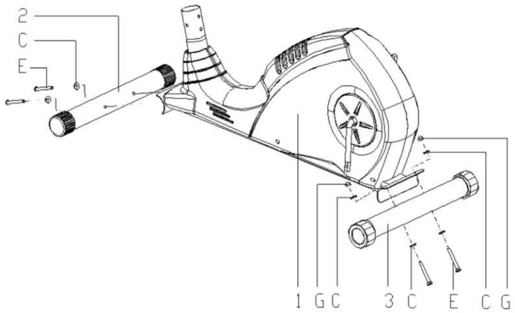
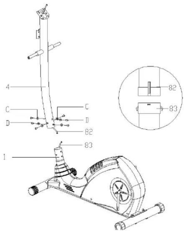
Construction - Step 2
Connect the sensor cable (82) to the extension cable (83). Then, attach the handle holder (4) to the main frame (1) using screws (D) and nuts (C).
Construction - Step 3
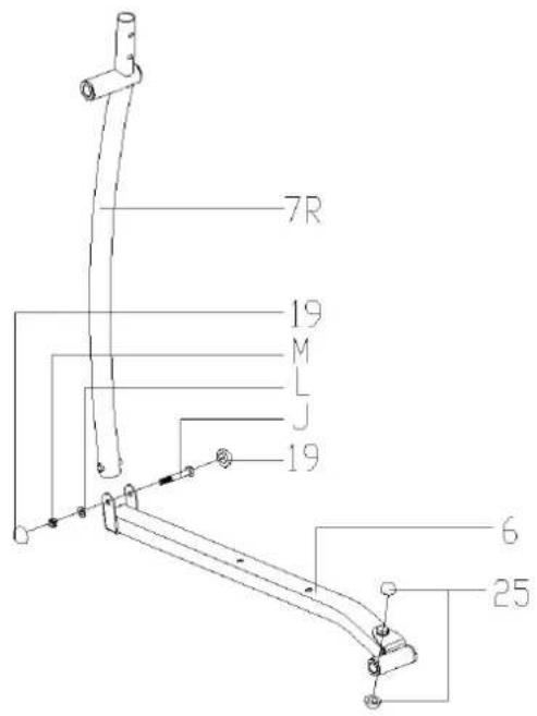
- Attach the flywheel rod (7R / L) to the pedal rods (6R / L) and fasten them with screws (J), washers (L) and nuts (M).
- Press the round caps (19 and 25) into the openings provided.
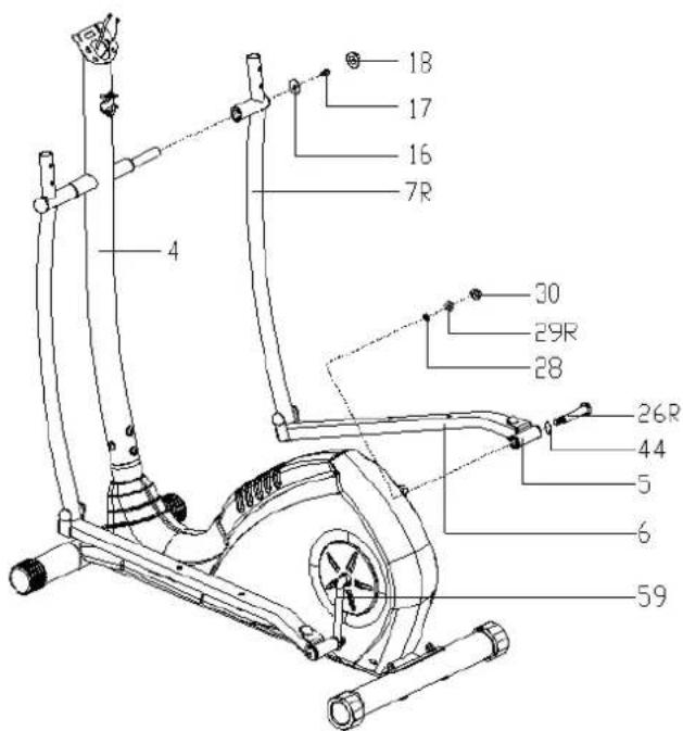
Construction - Step 4
- Attach the flywheel rod (7R) to the long end of the handle holder (4) with screws (J) and washers (L).
- Attach the rod joint (5) to the crank (59) with the screw (26R), spring washer (28), washer (44) and nut (29R).
- Press the round caps (18 and 30) into the openings provided.
- Attach the flywheel rod on the other side in the same manner.
- Caution: The screws for the levers are marked with L and R for left and right.
Construction - Step 5
Attach the pedals (21L / R) to the pedal rod with screw (K), nut (23) and washer (22).
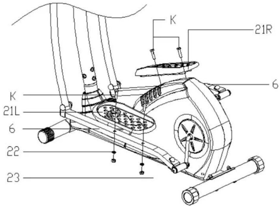
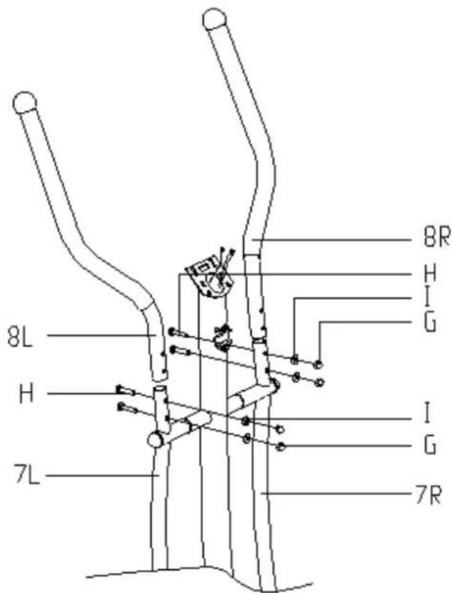
Construction - Step 6
Attach the handles (8L / R) to the flywheel rod (7L / R) with screw (H), nut (G) and bent grooved disc (I).
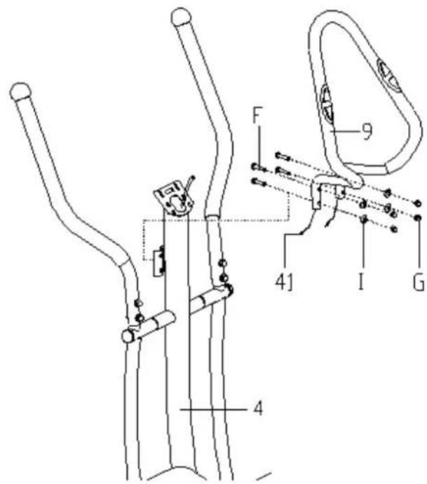
Construction - Step 7
Attach the palm rest (9) to the handle holder (4) with screws (F), curved washers (I) and cap nuts (G).
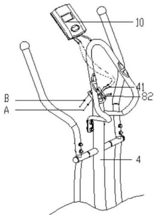
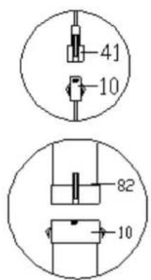
Construction - Step 8
Connect the pulse cable (41) to the sensor cable (82) with the display as shown. Slide the computer into the computer bracket and screw it onto the handle holder (4) with Phillips screws (A) and washers (B).
The Training Computer
Operating Elements and Functions
| ENTER | In stop mode (display: 'Stop'), press key to access the program selection;In menu or after entry: confi rm the selected item and the command;In start mode (display ,Start'), press:a) tempo,b) RPM (revolutions per minute) orc) display both in alternating sequence.In all modes: hold two seconds to clear all settings. |
| START / STOP | Start and stop the program,Push and hold for two seconds to clear all settings. |
| UP (over) | In stop mode or during editing: to select the next higher value or the previous entry;During training: to increase the training resistance. |
| DOWN (under) | In stop mode or during editing: to select the next lower value or the next entry;During training: to decrease the training resistance. |
| PULSE RECOVERY | Press to measure the current fi tness (,Pulse Recovery Test': determines your fi tness level from the return of your exercise heart rate to resting pulse. Press again to exit the function. |
Operation
Plug the power adapter into an electrical outlet and connect the training computer. Once it is connected, it will turn on automatically with a beep.
Programs
Manual program P 1

Automatic programs P 2-7

Wave

Valley

Fat burning

Ramp
Mountain

Interval
Pulse control programs P 8-11

natural_image
Four pixelated black-and-white grid patterns, no text or symbols presentSelection and setting
a) Manual program P1 and programs P2-P7
- Use the arrow keys (UP / DOWN) to select the desired program. The pictograms (see above) illustrate the structure of the program.
- Confir rm your selection with ENTER. The time setting appears on the display.
- Set the desired program time with the arrow keys and press ENTER. Next, the selection of the desired running distance is displayed.
- Set the desired distance using the arrow keys and confirm again with ENTER. Finally, the adjustment of the desired calorie burn target is displayed.
• Proceed in the same way. - Now press START / STOP to start the selected program.
The setting of all programs 1-7 follows the same pattern.
Program P8: In this program, set a target heart rate in order to achieve training within a specific pulse frame.
- Select the desired program using the arrow keys (UP / DOWN) and confirm your selection with ENTER.
- Set program duration, distance and target calorie counter as in programs 1-7.
- Enter your target pulse using the additional setting TARGET HEART RATE and confirm with ENTER.
- Now press START / STOP to start the selected program.
Programs P9 - P11
In these programs, you can enter your age and the training computer will provide a guideline for your maximum pulse.
- The P9 program targets approximately 55% of the maximum pulse, P10 program about 75% and P11 program 90%.
- Select the desired program using the arrow keys (UP / DOWN) and confirm your selection with ENTER.
- Set program duration, distance and target calorie counter as in programs 1-8.
- In the final step, enter your age, and then press ENTER.
- Now press START / STOP to start the selected program.
Please note:
During exercise, the heart rate depends on the speed, the difficulty setting (resistance) and the duration of the training. The programs 8-11 ensure that you move within the selected target heart rate by automatically adjusting the resistance of the measured pulse rate if you do not slow down and reduce your pulse yourself.
Pulse Measurement:
Please encircle the contact surfaces on the handle with both hands. After a short time (3 - 5 seconds), the training computer displays your pulse on the display. During the measurement, a flashing heart appears.
Please note: While being measured, your pulse is not immediately displayed as stable and may appear to be staggering. This measurement fluctuation settles down after a while.
Although you can use the measured values as a guide, never use them as the basis for medical treatment.
Pulse Recovery Test
The Pulse Recovery Test compares your heart rate before and after a training session and thus determines your fitness level.
- Take hold of the contact surfaces on the handle with both hands. After a short time, the display shows your current pulse.
- Press RECOVERY to start the test.
- Keep embracing the contact areas with your hands. The image displayed on the display timer counts down 60 seconds and at the end of the test, displays a code (F1.0 to F6.0). This means F1.0 = excellent fitness; F2.0 = good; F3.0 = fair; F4.0 = below average; F5.0 = needs improvement; F6.0 = needs strong improvement.
- If the training computer cannot determine your heart rate, the RECOVERY button stays on with no function.
- Press the RECOVERY key during the test if you want to end the test.
Information on Display
| Tempo | Display in km/h in the form 0.0 - 99.9 |
| RPM (rotations per minute) | Display of rotations per minute in the form 0 - 999 |
| DIST | Display of distance traveled in kilometres in the form 0.0 - 99.9 - 999.When the Distance program is selected, the display shows a countdown from the set target distance and signals when the target distance is reached with a beep. |
| CALORIE | Display of the (average) calculated calorie burn in the form of 0.0 - 99.9 - 999.Default: 10.0 - 90.0 - 990.When the calorie program is selected, the display shows a countdown from the set target distance and signals when the target distance is reached with a beep. |
| PULSE | Display of pulse frequency from 30-240 (beats per minute). |
| RESISTANCE LEVEL | Display of difficulty level from 1-8. |
| WATT | Display of the energy expenditure in watts from 0 - 999 |
| AGE | Display of the entered age (10-100) |
| ERROR 1 | Displayed when something is wrong. Check the monitor and the wiring, and disconnect the training computer from the network connection for a while if necessary. Restart. |
Disposal Considerations

natural_image
Symbol of a trash bin crossed out by a diagonal line, representing no waste or discharge (no text or labels present)According to the European waste regulation 2002/96/EG, this symbol on the product or on its packaging indicates that this product may not be treated as household waste. Instead it should be taken to the appropriate collection point for the recycling of electrical and electronic equipment. By ensuring this product is disposed of correctly, you will help prevent potential negative consequences for the environment and human health, which could otherwise be caused by inappropriate waste handling of this product. For more detailed information about recycling of this product, please contact your local council or your household waste disposal service.
Declaration of Conformity
Manufacturer: Chal-Tec GmbH, Wallstraße 16, 10179 Berlin, Germany.
This product conforms to the following European regulations:
2011/65/EU (RoHS)
2014/30/EU (EMV)
CE
Chère cliente, cher client,
natural_image
Pure mechanical component outline diagram without any text, numbers, or symbolsS(17-17-19)-2

natural_image
Simple line drawing of a double-ended wrench (no text or symbols)S(13-14)


Montage - Étape 1
Montage - Étape 2
Montage - Étape 4
Montage - Étape 7
Montage - Étape 8
natural_image
Four pixelated black-and-white grid patterns, no text or symbols presentnatural_image
Symbol of a trash bin crossed with a diagonal line, no text or numbers present


- Aufbau - Schritt 1
- Aufbau - Schritt 2
- Aufbau - Schritt 4
- Aufbau - Schritt 7
- Warning and Safety Instructions
- Construction
- Construction - Step 1
- Construction - Step 2
- Construction - Step 3
- Construction - Step 4
- Construction - Step 5
- Construction - Step 6
- Construction - Step 7
- The Training Computer
- Operating Elements and Functions
- Operation
- Programs
- Pulse control programs P 8-11
- Selection and setting
- a) Manual program P1 and programs P2-P7
- Programs P9 - P11
- Please note:
- Pulse Measurement:
- Pulse Recovery Test
- Disposal Considerations
- Declaration of Conformity
- Chère cliente, cher client,
- Montage - Étape 1
- Montage - Étape 2
- Montage - Étape 7
Brand : Klarfit
Model : Mobi Supreme
Category : Exercise bike