I 160 - Heating Jøtul - Free user manual and instructions
Find the device manual for free I 160 Jøtul in PDF.

User questions about I 160 Jøtul
0 question about this device. Answer the ones you know or ask your own.
Ask a new question about this device
Download the instructions for your Heating in PDF format for free! Find your manual I 160 - Jøtul and take your electronic device back in hand. On this page are published all the documents necessary for the use of your device. I 160 by Jøtul.
USER MANUAL I 160 Jøtul
GB - Installation and Operating Instructions 16
Mol homocysteine (14) (Sigma- -glyceroamide-2-oxoate) 897.06-13 (Starch for acetyl glycerophosphate; Voluting co
Tabletier:
Janu1 150/160 mnmats
Produktansvartig: Jatul AS
m = 311
Avail for Dokumentation
Ovinn Brundt
Forkker
MNTFNE
Se ogsa: www.sintef.no
NORSK
4.6 Klargjøring/montering
Bottles 24 June 2004
SPSveriges Provnings-och Forskningsinstitut
Coforing
Innovative health care

SP Energes Provnings-Oh Fornkngnngnab AB
Palaekos Thir74 Gouranee Easly/Net
2015年生
Dte eetat bnte aenrnnnne nnnnne ennnnne ennnnne ennnnne ennnnne ennnnne
m = 311 ;
m = 311 ;
1.0 Relationship to the authorities
Installation of a fireplace must be according to local codes and regulations in each country.
All local regulations, including those that refer to national and European standards, shall be complied with when installing the product.
Instructions for mounting, installation and use are enclosed with the product. Prior to using the product the installation must be inspected by a qualified person.
A product data label in heat resistant material can be found on the heat shield at the back of the product. This contains information about identification and documentation for the product.
2.0 Technical data
Material: Cast iron
Finish: Grey varnish
Fuel: Wood
Log length, max.: 40 cm
Flue outlet: Top
Flue dimension: 150mm / 177cm
Approx. weight: 105kg
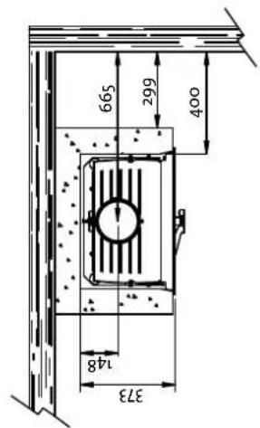
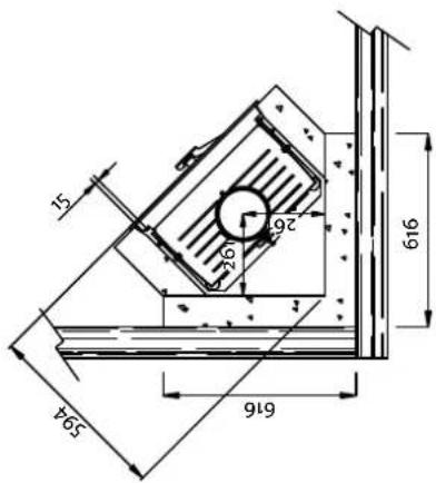
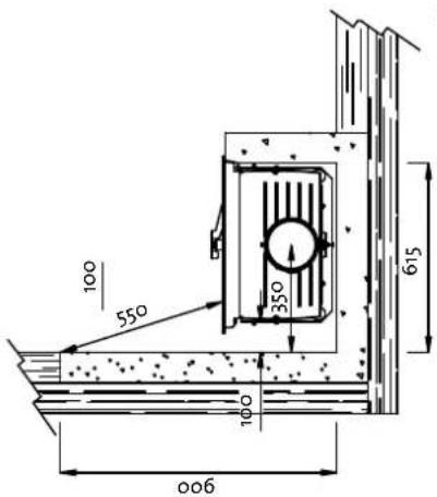
Dimensions, distances etc.: See fig.1
Technical data according to EN 13229
Nominal heat output: 6 kW
Smoke gas mass flow: 5,8 g/s
Recommended chimney draught: 12 Pa
Efficiency: 75% @6,8kW
CO emission (13% O2): 0,16%
Flue gas temperature: 342°C
Operating mode: Intermittent
3.0 Safety precautions
3.1 Fire preventive measures
Any use of the fireplace may represent some danger. Therefore, respect the following instructions:
- Ensure that furniture and other combustible materials do not get too close to the fireplace.
- Let the fire die. Never extinguish it with water.
- The fireplace gets warm when used and may cause burns if touched.
- Only remove the ashes when the stove is cold.
- Ash must be properly disposed of outdoors, or emptied where it does not present a fire hazard.
3.2 Air supply
Warning! Please ensure that there is adequate air supply from the outdoors to the room in which the fireplace is to be installed. Ensure that air vents in the room where the fireplace is located are not blocked.
An inadequate air supply could cause smoke gas to escape into the room. This is very dangerous! Symptoms of this include smoky smell, drowsiness, nausea and feeling ill.
Avoid using mechanical fan vents in a room with a fireplace. This may cause negative pressure and draw poisonous gasses into the room.
4.o Installation
4.1 Floor
Foundations
Ensure that the floor is strong enough for the fireplace. See «2.0 Technical data» for weights.
Combustible floor protection
If the fireplace is to be mounted on a combustible floor, cover the floor under and in front of the fireplace with a plate made of metal or other non-combustible material. The recommended minimum thickness is 0,9 mm.
Any flooring made of combustible material, such as linoleum, carpets, etc. must be removed from under the floor plate.
Requirement for protecting combustible flooring in front of fireplace
The front plate must be in accordance with national laws and regulations.
Contact your local building authorities regarding restrictions and installation requirements.
4.2 Wall
Distance to walls protected by a firewall - see fig. 1
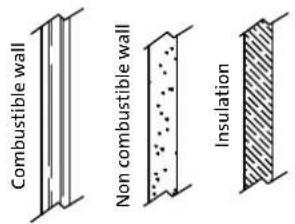
Firewall requirement
The firewall must be at least 100mm thick and be made of brick, concrete-stone or light concrete. Other materials and constructions with satisfactory documentation may also be used.
Contact your local building authorities regarding restrictions and installation requirements.
Min. distance from heat shield to a firewall: 15 mm.
Requirements for the stove surround
Note that the entire back panel within the surround must be covered by firewall.
If the stove cowling is bricked up to the ceiling and the ceiling is made of combustible material, on top of the warming chamber and the cowling vents an extra ceiling panel must be installed to avoid heating the ceiling.
For example use:
Rock wool 100 mm thick on top of a steel plate min. 0,9 mm.
Ensure airing out the top of the stove cowling - for example an opening towards the ceiling, or approx. 5cm^2 opening (fig. 2A).
Note: Remember that it should be possible to sweep and to inspect the installation.
Note: When the door is open, you have to secure the product to prevent it from tipping forward, see 4.7 Set up/installation.
ENGLISH
4.3 Air supply
Air should be allowed to flow between the insert and the brickwork.
The required air vent sizes for Jøtul I 160 (for air circulation) are:
Base: Minimum of 350 cm² free ventilation.
Top: Minimum of 500 cm ^2 free ventilation.
This is a safety measure to prevent a build up of heat in the surround, and also to ensure sufficient heat emission into the room.
If the house is badly ventilated, the room must be equipped with extra fresh air circulation, for example by means of a separate channel under the base of the fireplace.
The fresh air channel should be as straight as possible, and it should be possible to close the channel with a damper in order to keep out cold air when the fireplace is not being used. A good choice would be Jotul's own fresh air damper, catalogue no: 340654.
4.4 Ceiling
Jøtul I 160 have been approved for: a min. 300 mm distance from warm air opening in the hood's top to a ceiling of combustible material.
4.5 Chimney
- The fireplace can be connected to a chimney and flue pipe approved for solid fuel fired fireplaces with flue gas temperatures specified in «2.0 Technical data».
- The chimney's cross-section must be at least as big as the flue pipe's cross-section. See «2.0 Technical data» when calculating the correct chimney cross-section.
Several solid fuel fired fireplaces can be connected to the same chimney if the chimney's cross-section is sufficient. - Connection to the chimney must be carried out in accordance with the installation instructions from the supplier of the chimney.
- Before making a hole in the chimney the fireplace should be test-mounted in order to correctly mark the position of the fireplace and the hole in the chimney. See fig. 1 for minimum dimensions.
- Ensure that the flue pipe is inclined all the way up to the chimney.
- Use a flue pipe bend with a sweeping hatch that allows it to be swept.
Be aware of the fact that connections must have a certain flexibility in order to prevent movement in the installation leading to cracks.
N.B. A correct and sealed connection is very important for the proper functioning of the product.
Warning! Weight from the fireplace must not be transferred to the chimney. The fireplace must not interfere with the ability of the chimney to move and it must not be fastened to the chimney.
Note: A guide is published by the British Flue and Chimney Manufacturers' Association which contains general information on chimneys and flues.
Recommended chimney draught, see «2.o Technical data». If the draught is too strong you can install and operate a flue damper to control the draught.
In case of chimney fire
- Close all hatches and vents.
- Keep the firebox door closed.
- Check the loft and cellar for smoke.
Call the fire service. - Before use after a fire an expert must check the fireplace in order to ensure that it is fully functional.
4.6 Preparation/installation
Make sure that the fireplace insert is free of damage before commencing with the installation.
The product is heavy! Make sure you have assistance when erecting and installing the fireplace.
Attaching the legs (fig. 3-4)
- After unpacking the insert, take out the box with its contents, the baffle plate and the heatshields. You may also remove the grate, the rear bottom plate and the ash drawer.
- Close the door. Place the cardboard packaging on the floor and lay the fireplace carefully down on its back.
- If the foot screws are to be used: If the product is assembled directly on a plate, the foot screws are to be used. These screws are already fittet in the bottom plate, see fig. 4. It is important that the leg supports are used under the screws, see fig. 4.
- If long legs are to be used: Assemble the 3 legs (A) with the aid of flush screws M6 × 25 mm and washers. (The screws and washers are included in the plastic bag).
- Attach the adjustable joints (3B) to the legs.
- Assemble the heat shield (3D) under the base of the fire with the aid of 1 collar head screws which is fastened under the base plate.
Note: When the door is open, the main point of the product is in front. Secure the product to prevent it from tipping forward.
- Put the baffle plate in place at the top of the burn plates.
- The final adjustments should only be made after the insert has had a trial assembly. Always place the leg supports under the screw heads, both to protect the surface and to prevent the insert from slipping out of position.
- Adjustment of the long legs is done with the aid of M10x35mm screws which are attached to the joints (3C).
Securing the heat shield for the flue pipe (fig. 5)
The heat shield for the flue pipe is fixed to the back of the rear heat shield by means of the two tapping screws that you will find in the bag of screws.
If a bend is to be used in the flue pipe from the stove directly into the chimney, which lies behind the stove, this heat shield may be in the way. As normally there will be no flammable material in the wall behind the stove and the heat shield may then be removed.
4.7 Set up/installation
Assembly of the chimney
- Initially, assemble and provisionally position the insert without making any holes in the chimney.
- The insert may be assembled with either an 150mm dia.) or an 175mm dia.). The flue pipe bend should be assembled directly onto the insert and should be able to be turned through 360^ . The flue pipe bend 150mm dia is fitted to the inside of the smoke outlet and 175mm dia is fitted to the outside of the smoke outlet. Make sure the flue pipe has a sweeping hatch with reversal in order to ensure that sweeping is possible.
- Adapt the flue pipe's length with an overlap of 40~mm both in the flue pipe bend and in the chimney collar.
- Press the appropriate flue pipe into the chimney collar. Fix this in place by means of the provided gasket cord.
- Place the insert in its final position. Use the gasket cord/ furnace cement to install the flue pipe bend in the insert's flue pipe collar and in the appropriate pipe.
- The flue pipe bend must be attached to the smoke outlet at the front edge with an M6 self cutting screw (fig. 10D). Use an 5,5 mm drill and make a hole in the flue pipe for the screw.
NB! It is important that the joints are completely sealed. Otherwise the operation of the fire may be impaired.
To avoid the product to tip forward, the two brackets in the sides are to be used. See fig.7A.
- Loosen the screws and push the steel brackets towards the sides of the surrounding.
- Refasten the screws.
4.8 Control of functions (fig. 6)
When the product is set up, always check the control functions. These shall move easily and function satisfactorily.
Air vent control (A)
Left position = closed
Right position = fully open
Ignition vent control (B)
Pushed in = closed
Pulled out = open
5.0 Use
5.1 Choice of fuel
Always use quality firewood. This will give you optimal results, and will not cause any damage to the product.
5.2 Jøtul's definition of quality firewood
With good quality firewood we mean logs of, for example: Birch, beech and oak.
Good quality wood should be dried so that the water content is approx. 20% .
To achieve that, the wood should be cut during late winter or early spring, then cut and stacked to ensure proper airing and covered to prevent it from absorbing rainwater. The logs should be taken indoors in autumn for use during the winter season.
The amount of energy obtainable from 1kg of wood varies very little. On the other hand the specific weight of the different kinds of wood varies considerably. As an example, a certain volume of birch will provide less kWh than the same volume of oak, which has a higher specific weight.
The amount of energy produced by 1kg quality wood is about 3,8 kWh.1 kg of completely dry wood (o % humidity) produces approximately 5 kWh, while wood with a humidity level of 60% produces only around 1,5 kWh/kg.
Consequences of using damp wood may include:
- Appearance of soot/tar on the glass, in the fireplace and in the chimney.
The fireplace emits little warmth. - Risk of chimney fire as a consequence of accumulation of soot in the fireplace, flue pipe and chimney.
The fire may die out.
Be especially careful never to lay a fire using any of the following materials:
Household waste, plastic bags, etc.
- Painted or impregnated wood (highly toxic)
- Chipboard or laminated boards
- Driftwood
This may harm the product and pollute the atmosphere.
N.B. Never use combustible liquids such as petrol, kerosene, red spirit or similar to start the fire. This may cause harm to both yourself and the product.
5-3 Log length and amount
The maximum length of logs to be used is 40 cm. Nominal heat emission from a Jøtul I 160 is 6 kWh. The requirement for nominal heat emission is 2,1 kg of quality firewood per hour.
The Jotul I 160 is a product that uses an extra air supply to enable the afterburning of hazardous gases and particles. It is important that the system is used correctly.
Another important factor for proper fuel consumption is that the logs are the correct size. The size of the logs should be:
Kindling:
Length: Approx 30 cm
Diameter: 2 - 5 cm
Amount per fire: 8-10 pieces
ENGLISH
Firewood (split logs):
Recommended length: 30 - 35 cm
Diameter: Approx. 8 - 12 cm
Intervals for adding wood: Approximately every 50 minutes
Size of the fire: 1,7 kg
5.4 Initial lighting
Light the fire as described under «5.5 Daily use».
Light the fire for a couple of hours and ventilate any smoke and smell from the product.
- Repeat this a couple of times.
Note! Odors when using the stove for the first time.
Painted products: The fireplace may emit an irritating gas when used for the first time, and it may smell a little. The gas is not toxic, but the room should be thoroughly ventilated. Let the fire burn with a high draught until all traces of the gas have disappeared and no smoke or smells can be detected.
Enamelled products: Condensation may form on the surface of the fireplace the first few times it is used. This must be wiped off to prevent permanent stains forming when the surface heats up.
5.5 Daily use
The product is intended for intermittent combustion. By intermittent combustion one means normal use of a fireplace, meaning that each fire should burn down to embers before new firewood is added.
- Open both vents fully (fig. 6A-B). (Use a glove, for example, as the handle can become hot.)
- Place two medium sized logs in/out on each side of the base.
- Crumple some newspaper (or birch bark) between these and add some kindling wood in a criss-cross pattern on top and light the newspaper. Increase the size of the logs gradually.
- Leave the door slightly open until the logs catch fire. Close the ignition vent when the firewood has ignited and the fire is burning briskly.
- Check that the afterburning (secondary combustion) starts. This is best indicated by yellow, flickering flames at the air chamber.
- Then regulate the rate of combustion to the desired level of heating by adjusting the airvent (fig. 6A).
Nominal heat emission is achieved when the air vent is open approximately 50% .
5.6 Adding firewood
Each load should burn down to embers before new firewood is added. Open the door slightly and allow the negative pressure to level out prior to opening the door completely.
- Add the wood and make sure that the air vent is fully open for a few minutes until the wood has caught fire.
Regulate the air vent once the wood has properly ignited and is burning well. Check that afterburning (secondary combustion) starts.
N.B. Danger of overheating: the fireplace must never be used in a manner that causes overheating.
Overheating occurs when there is too much wood and/or air so that too much heat is developed. A sure sign of overheating is when parts of the fireplace glow red. If this happens, reduce the ventilation opening immediately.
Upon suspicion of excessive/poor draught in the chimney, seek professional help. See also «2.0 Technical data» and «4.5 Chimney» for information.
5.7 Using fireplace during the transition from winter to spring
During a transitional period with sudden fluctuations in temperature, negative smoke draught or under difficult wind conditions, disturbances in the chimney draught may occur so that the smoke gasses are not drawn out.
One should then use less firewood and have a larger opening in the air vents so that the wood burns fresher and faster. In this was the draught in the chimney will be maintained.
To avoid accumulated ash, it should be removed more often than usual. See «6.2 Ash removal».
6.o Maintenance
6.1 Cleaning the glass
Jotull 160 is equipped with an air wash for the glass. Air is sucked in through the air vent above the fireplace and down along the inside of the glass.
However, some soot will always stick to the glass, but the quantity will depend on the local draught conditions and adjustment of the air wash vent. Most of the soot layer will normally be burned off when the air wash vent is opened all the way and a fire is burning briskly in the fireplace.
Good advice! For normal cleaning, moisten a paper towel with warm water and add some ash from the burn chamber. Rub it over the glass and then clean the glass with clean water. Dry well. If it is necessary to clean the glass more thoroughly we recommend using a glass cleaner (follow the instructions on the bottle).
6.2 Ash removal (fig. 8)
See the description below about how to handle ash: «3.1 Fire preventive measures».
- Open the fire grate.
- Lift out and empty the ash pan.
- Place the grate gently down as it is heavy
- Ideally, some ash should be left as a protective layer for the bottom of the fireplace.
6.3 Cleaning and soot removal
Soot deposits may build up on the internal surfaces of the insert during use. Soot is a good insulator and will therefore reduce the fireplace's heat output. If soot deposits accumulate when using the product, they can be easily removed by using a soot remover.
In order to prevent a water and tar layer from forming in the insert you should regularly allow the fire to burn hot in order to remove the layer. An annual internal cleaning is necessary to get the best heating effect from the product. It is a good idea to do this in connection with sweeping the chimney and flue pipes.
6.4 Sweeping of flue pipes to the chimney
The flue must be swept through the stove's door opening. The baffle plate must first be removed. See «7.o Service».
6.5 Control of the stove
Jotul recommends that you personally control your product carefully after sweeping/cleaning. Check all visible surface areas for cracks. Also check that all joints are sealed and that the gaskets are in the correct position. Any gaskets showing signs of wear or deformation must be replaced.
Thoroughly clean the gasket grooves, apply ceramic glue (available from your local Jøtul dealer), and press the gasket well into place. The joint will dry quickly.
6.5 External maintenance
Painted products may change colour after several years usage. The surface should be cleaned and brushed free of any loose particles before new paint is applied.
Enamelled products must only be cleaned with a clean, dry cloth. Do not use water and soap. Any stains can be removed with cleaning liquids. (Oven cleaner etc.)
7.o Service
Warning! Any unauthorised change to the product is illegal! Only use original spare parts!
Changing the burn plates, base plate and baffle plate (fig. 9-10)
- The baffleplate (fig. 9A), which is resting on the burn plates, has to be edged down and lifted out.
- Lift the grate and the base plate (fig. 10A - B) up and out
- Remove the burning plates (fig. 10C).
For reinstallation follow the same procedure in the opposite sequence.
8.o Optional equipment
The product has no optional equipment.
9.o Reasons for operational problems - troubleshooting
Poor draught
- Check the length of the chimney and that it complies with national laws and regulations. Make sure that the minimum cross section on the chimney is large enough. See also «2.0 Technical data» and «4.5 Chimney» for information.
- Make sure that there is not anything preventing the smoke gasses from escaping: Branches, trees, etc.
The fire extinguishes after a while
Make sure that the firewood is sufficiently dry
Find out whether there is negative pressure in the house, close mechanical fans and open a window close to the stove.
- Check that the air vent is open.
- Check that the flue outlet is not clogged by soot
Unusual amount of soot accumulates on the glass
Some soot will always stick to the glass, but the quantity depends on:
- Humidity of the fuel.
The local draught conditions
Regulating the air vent.
Most of the soot will normally burn off when the air vent is opened all the way and a fire is burning briskly in the fireplace.
See «6.1 Cleaning the glass - good advice»
FRANÇAIS
Sommaire
Position tiree = ouvert
Durchmesser: 2 - 5 cm
Brennholz (Scheite):
Emphelte Lunge: 30 - 35 cm
Durchmesser: ca. 8 - 12 cm
Min. mal frontplate / measure frontplate
X/Y=Acc.to national regulatives and regulations.
4-4137-P05
Mälene gjelder ubehandeldeprodukter. Etter lakkering erer emaljering kan malene variere noe. Dimensions refer to untreated products. After painting or enamelling dimensions may have small divergences.
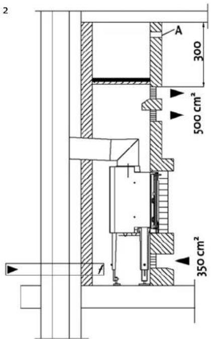
Fig. 2
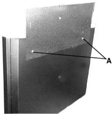
Fig. 5
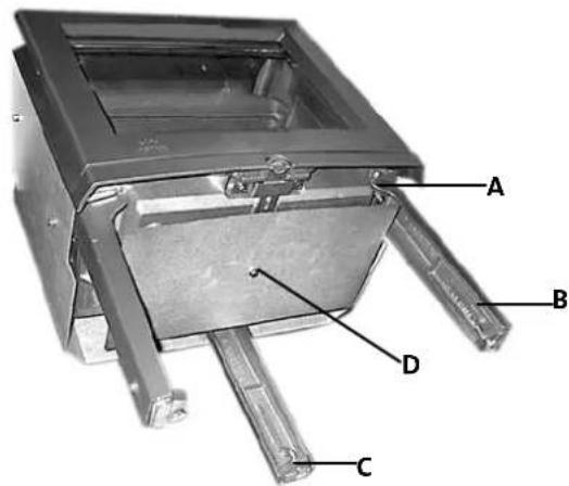
Fig. 3
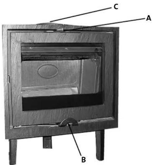
Fig. 6
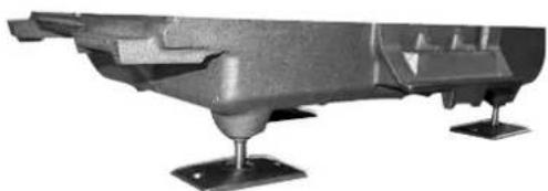
Fig. 4
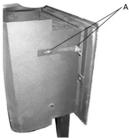
Fig. 7
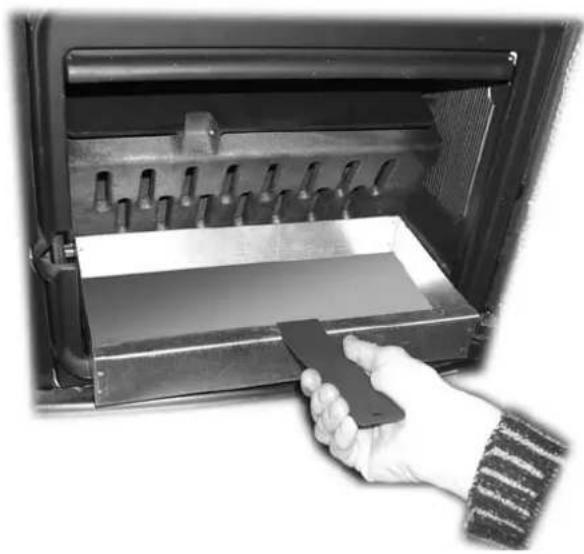
Fig. 8
Fig. 9
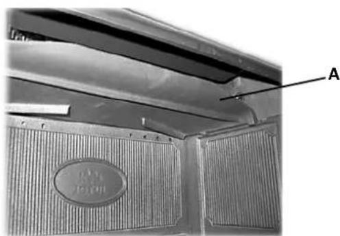
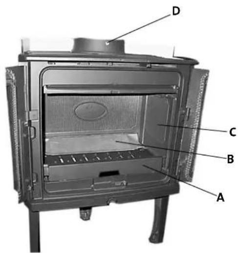
Fig. 10
Checked
Utfort Kontrollpunkt Controlled item
Jøtul pursue a policy of constant product development. Products supplied may therefore differ in specification, colour and type of accessories from those illustrated and described in the brochure.
Jotul AS has a quality system that conforms to NS-EN ISO 9001 for product development, manufacturing, and distribution of stoves and fireplaces. This policy gives our customers quality and safety piece of mind as a result of Jotul's vast experience dating back to when the company first started in 1853.