
PDR 80 - Subwoofer Paradigm - Free user manual and instructions
Find the device manual for free PDR 80 Paradigm in PDF.

| Product Type | Active subwoofer |
| Model | PDR 80 |
| Brand | Paradigm |
| Speaker driver | 210 mm (8 in) reinforced polymer composite cone, 35.5 mm (1-1/2 in) voice coil |
| Built-in amplifier | 300 watts dynamic peak / 100 watts RMS continuous, high current, discrete output |
| Low frequency extension | 32 Hz (DIN) |
| Crossover frequency | Variable 50 Hz – 150 Hz with bypass option |
| Phase adjustment | 0° or 180° |
| Inputs | Two RCA (L/R-Mono) line level |
| Power | On/Auto/Standby switch, standby consumption < 0.5 W (wired), < 1 W (wireless) |
| Dimensions (H x W x D) | 35.6 x 30.5 x 36.2 cm (14 x 12 x 14-6/16 in) |
| Weight (unpacked) | 10.9 kg (24 lb) |
| Finish | Ash black |
| Warranty | 3 years against defects in materials and workmanship |
| Care and cleaning | Clean with a soft damp cloth, avoid strong detergents and wet objects on the unit |
| Safety | Do not open, risk of electric shock; do not expose to water; adequate ventilation |
| Break-in | Several hours of operation before critical listening recommended |
Frequently Asked Questions - PDR 80 Paradigm
User questions about PDR 80 Paradigm
0 question about this device. Answer the ones you know or ask your own.
Ask a new question about this device
Download the instructions for your Subwoofer in PDF format for free! Find your manual PDR 80 - Paradigm and take your electronic device back in hand. On this page are published all the documents necessary for the use of your device. PDR 80 by Paradigm.
USER MANUAL PDR 80 Paradigm
natural_image
Black-and-white photo of a woman sitting in a modern chair with a speaker nearby (no text or symbols visible)PDR SUBWOOFER SERIES
OWNERS MANUAL
natural_image
Close-up of a wooden speaker with concentric sound waves, labeled 'Paradigm' on the side (no other text or symbols visible)

Thank you for choosing Paradigm PDR subwoofers and congratulations! You are about to hear the difference these high-performance subwoofers will make in your music and home theater system. They are the product of countless hours of comprehensive research and development and will reward you with superior high-end sound for many years.
To achieve all of the exceptional sound they are capable of providing requires care in installation and operation. Please take the time to read this manual and follow all instructions. If you have further questions, please contact your Authorized Paradigm Dealer or visit the Q&A page on our website at www.paradigm.com.
TABLE OF CONTENTS
Safety Precautions 2
Important Safety Instructions . . . 3
Back-Panel: Controls and
Connections (Pictorial) ..... 4
Subwoofer Placement
(Pictorial) 6
Connecting Your
Subwoofer (Pictorial) 6
Pairing Your Wireless Subwoofer with the Transmitter (Pictorial) .. 7
Your New Subwoofer ..... 8
Power Requirements 8
Room Acoustics 8
Subwoofer Placement ..... 8
Wireless Operation 9
Subwoofer Connection .....10
Fine Tuning .....10
Specifications .....12
Limited Warranty ....13

FCC ID: WU0-WRX1010. This device complies with Part 15 of the FCC Rules. Operation is subject to the following two conditions: (1) This device may not cause harmful interference, and (2) This device must accept any interference received, including information that may cause undesired operation. Changes or modifications not expressly approved by the party responsible for compliance could void the user's authority to operate the equipment.

RECYCLING AND REUSE GUIDELINES FOR EUROPE
In accordance with the European Union WEEE (Waste Electrical and Electronic Equipment) directive effective August 13, 2005, we would like to notify you that this product may contain regulated materials which, upon disposal, according to the WEEE directive, require special reuse and recycling processing. For this reason Paradigm Electronics Inc. (manufacturers of Paradigm speakers and Anthem electronics) has arranged with our distributors in European Union member nations to collect and recycle this product at no cost to you. To find your local distributor please contact the dealer from whom you purchased this product or go to our website at www.paradigm.com.
Please note that the product only falls under the WEEE directive. When disposing of packaging and other shipping material we encourage you to recycle through the normal channels.
SAFETY PRECAUTIONS
READ THIS SECTION CAREFULLY BEFORE PROCEEDING!

WARNING
RISK OF ELECTRIC SHOCK DO NOT OPEN

WARNING: TO REDUCE THE RISK OF ELECTRIC SHOCK, DO NOT REMOVE COVER (OR BACK). NO USER-SERVICEABLE PARTS INSIDE. REFER SERVICING TO QUALIFIED SERVICE PERSONNEL.
WARNING: TO REDUCE THE RISK OF FIRE OR ELECTRIC SHOCK, DO NOT EXPOSE THIS APPARATUS TO RAIN OR MOISTURE, AND OBJECTS FILLED WITH LIQUIDS, SUCH AS VASES, SHOULD NOT BE PLACED ON THIS APPARATUS.
CAUTION: TO PREVENT ELECTRIC SHOCK, MATCH WIDE BLADE OF PLUG TO WIDE SLOT, FULLY INSERT.

The lightning flash with arrowhead symbol within an equilateral triangle, is intended to alert the user to the presence of uninsulated "Dangerous voltage" within the product's enclosure that may be of sufficient magnitude to constitute a risk of electric shock to persons.

The exclamation point within an equilateral triangle is intended to alert the user to the presence of important operating and maintenance (Servicing) instructions in the literature accompanying the product.
CAUTION: FOR CONTINUED PROTECTION AGAINST RISK OF FIRE, REPLACE THE FUSE ONLY WITH THE SAME AMPERAGE AND VOLTAGE TYPE. REFER REPLACEMENT TO QUALIFIED SERVICE PERSONNEL.
WARNING: UNIT MAY BECOME HOT. ALWAYS PROVIDE ADEQUATE VENTILATION TO ALLOW FOR COOLING. DO NOT PLACE NEAR A HEAT SOURCE, OR IN SPACES THAT CAN RESTRICT VENTILATION.
IMPORTANT SAFETY INSTRUCTIONS
1) Read these instructions.
2) Keep these instructions.
3) Heed all warnings.
4) Follow all instructions.
5) Do not use this apparatus near water.
6) Clean only with dry a cloth.
7) Do not block any ventilation openings. Install in accordance with the manufacturer's instructions.
8) Do not install near any heat sources such as radiators, heat registers, stoves, or other apparatus (including amplifiers) that produce heat.
9) Do not defeat the safety purpose of the polarized or grounding-type plug. A polarized plug has two blades with one wider than the other. A grounding type plug has two blades and a third grounding prong. The wide blade or the third prong are provided for your safety. If the provided plug does not fit into your outlet, consult an electrician for replacement of the obsolete outlet.
10) Protect the power cord from being walked on or pinched particularly at plugs, convenience receptacles, and the point where they exit from the apparatus.
11) Only use attachments/accessories specified by the manufacturer.
12) Use only with the cart, stand, tripod, bracket, or table
specified by the manufacturer or sold with the apparatus. When a cart is used, use caution when moving the cart/ apparatus combination, to avoid injury from tip-over.
13) Unplug this apparatus during lightning storms or when unused for long periods of time.
14) Refer all servicing to qualified service personnel. Servicing is required when the apparatus has been damaged in any way, such as power-supply cord or plug is damaged, liquid has been spilled or objects have fallen into the apparatus, the apparatus has been exposed to rain or moisture, does not operate normally, or has been dropped.
15) DO NOT EXPOSE THIS EQUIPMENT TO DRIPPING OR SPLASHING AND ENSURE THAT NO OBJECTS FILLED WITH LIQUIDS, SUCH AS VASES, ARE PLACED ON THE APPARATUS.
16) TO COMPLETELY DISCONNECT THIS APPARATUS FROM THE AC MAINS, DISCONNECT THE POWER SUPPLY CORD PLUG FROM THE AC RECEPTACLE.
17) THE MAINS PLUG OF THE POWER SUPPLY CORD SHALL REMAIN READILY OPERABLE.
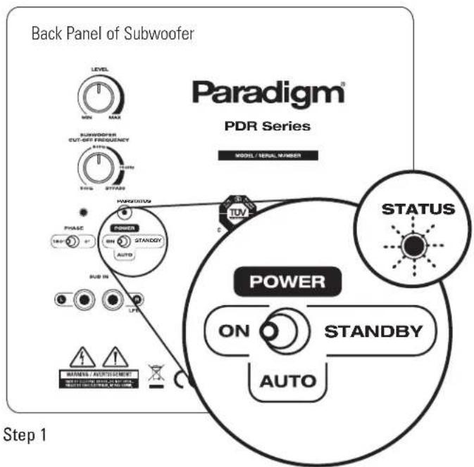
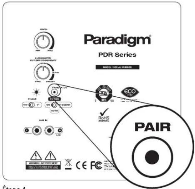
BACK PANEL: CONTROLS AND CONNECTIONS

① Subwoofer Level
Balances the subwoofer output level to your speakers.
② Subwoofer Cut-Off Frequency with Bypass Option
Controls the subwoofer's upper-frequency cut-off. This can be set to match the low-frequency roll-off characteristics of your front speakers. For example, if your front speakers play to approximately 80 Hz, you can set the subwoofer cut-off frequency to approximately 80 Hz.
3 Bypass option allows you to bypass the subwoofer's built-in cut-off control to let your preamp/processor's or receiver's internal bass management system provide the crossover function.
4 Status LED (wireless models only)
Indicates connection status between wireless subwoofer and transmitter (e.g. Not Paired, Searching for Connection, Paired). For additional information see text section 'Pairing Your Wireless Subwoofer with the Transmitter.'
BACK PANEL: CONTROLS AND CONNECTIONS (continued)
5 Pair (wireless models only)
This feature initiates wireless pairing between your wireless subwoofer and the transmitter.
⑥ Phase Alignment Switch (0 or 180°)
The sound from your subwoofer may arrive at the listening position out of phase with the front speakers. This switch synchronizes the subwoofer and the front speakers through their frequency overlap region.
7 On
When the toggle switch is in the 'On' position, your subwoofer remains continuously on.
8 Auto
This mode eliminates the need to repeatedly switch your subwoofer on and off — it will turn on when it receives an input signal. If no signal is sensed for a period of time, it will automatically switch to standby.
9 Standby
In this mode your subwoofer remains on standby. This uses very little power — the wired subwoofer uses less than 0.5 watts and the wireless model less than 1 watt.
10 Line-Level Input
Allows connection from the Sub/LFE Output of an A/V receiver, processor or other suitable low-level source.
SUBWOOFER PLACEMENT (Additional details in text section Subwoofer Placement)
natural_image
Simple 3D diagram of a rectangular area with curved and shaded regions, featuring a small cube on top (no text or symbols)Fig. 1a
natural_image
3D diagram of a rectangular grid with a small cube on top (no text or symbols)Fig. 1b Fig. 2
natural_image
Simple 3D diagram of a rectangular area with a central monitor and two side blocks, no text or symbols present.
natural_image
Simple 3D diagram of a rectangular area with a central monitor and two side blocks, no text or symbols present.CONNECTING YOUR SUBWOOFER (Additional details in text section Connecting Your Subwoofer)
WIRED CONNECTION
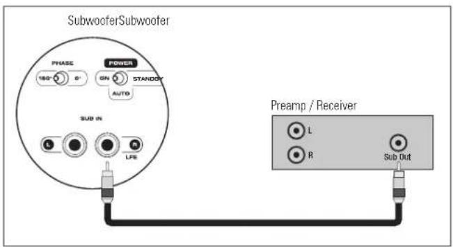
Fig. 3
flowchart
graph TD
    A["Phase"] --> B["160°"]
    B --> C["Power"]
    C --> D["ON"]
    D --> E["RTANETH"]
    E --> F["AUTO"]
    F --> G["SUB IN"]
    G --> H["LIFE"]
    H --> I["Preamp / Receiver"]
    I --> J["L"]
    I --> K["R"]
    J --> L["Power Amplifier"]
    K --> L
    L --> M["L + L - R -"]
    M --> N["Speakers"]
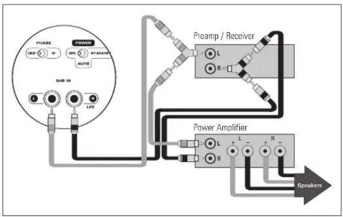
Fig. 4
(WIRELESS) CONNECTION
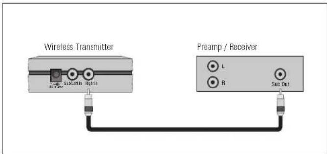
Fig. 5
flowchart
graph TD
    A["Wireless Transmitter"] --> B["Preamplifier"]
    A --> C["Power Amplifier"]
    B --> D["Speaker"]
    C --> E["Speaker"]
    style A fill:#f9f,stroke:#333
    style B fill:#ccf,stroke:#333
    style C fill:#cfc,stroke:#333
    style D fill:#fcc,stroke:#333
    style E fill:#cff,stroke:#333
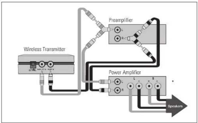
Fig. 6
'PAIRING' YOUR WIRELESS SUBWOOFER WITH THE TRANSMITTER
(Additional details in text section Pairing Your Wireless Subwoofer with the Transmitter)
IMPORTANT! Transmitter and subwoofer must be no more than 50' (15 m) apart in the room

Step 2

Step 3

Step 4
What do the blinking LEDs mean on Subwoofer and Transmitter?
Slow Blink = Not paired
Fast Blink = Searching for connection
Solid Glow = Paired (connection established between transmitter and subwoofer)
YOUR NEW SUBWOOFER
Break-In
Although your Paradigm subwoofer will sound great 'out of the carton' it will sound even better when broken in. Allow it to operate for several hours before you listen critically.
Cleaning
Do not use a strong or abrasive cleaner on your subwoofer. Clean it with a damp soft cloth, but do not get it wet. Do not place wet objects, such as drinking glasses or potted plants, on top of it. If allowed to soak in, even a small amount of water may permanently damage the enclosure.
POWER REQUIREMENTS
The 'Watts' (W) rating indicated on the back panel of your subwoofer is the typical AC power the unit will consume when producing its
maximum power output. However, the actual wattage consumption will vary with the bass content of the program material.
ROOM ACOUSTICS
You are about to experience the powerful and extremely accurate deep bass performance of Paradigm subwoofers. They offer incredible output with low distortion, exceptional extension and superb definition. It is important to note, however, that just as the amount of soft furnishings has a decided impact on mid and high frequencies, those frequencies below 150 Hz are dramatically affected by the room itself—its size, shape, as well as the physical boundaries of the room. The extra care you take in correctly positioning your subwoofer(s) will result in greater listening enjoyment. Keep the following guidelines in mind when deciding on best subwoofer placement:
- Concrete floors and walls tend to aggravate low-frequency standing wave problems and are less preferred.
- Rooms where height, width and length are similar should be avoided as they can exhibit significant low-frequency standing wave problems. This may result in reduced clarity. If no other room is possible, experiment with subwoofer placement to minimize acoustic problems.
SUBWOOFER PLACEMENT

To avoid personal injury, install subwoofer in a location where any rear amplifier parts such as panels and/or heatsinks, etc. cannot be accidentally touched.
Bass is less and less directional as it goes down in frequency. For best sonic integration, locating your subwoofer between your front speakers or beside one of them and close to the back wall will usually provide the best bass performance. If this location is not possible your subwoofer may be placed anywhere in the room without affecting the stereo image of your front speakers or the soundstage of your multichannel speaker system.
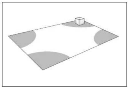
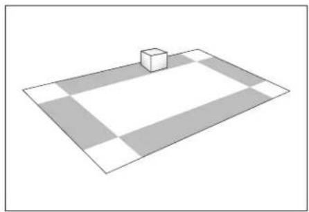
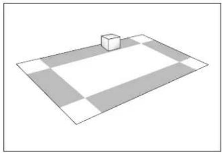
Fig. 1a and Fig. 1b highlight how bass output is generally affected by room placement. When seated in a typical listening area of your room, placing the subwoofer inside the 'shaded' areas will typically result in bass performance as follows:
Fig. 1a: Corner placement provides the most bass, but sometimes at the expense of accuracy.
Fig. 1b: A subwoofer placed near a wall usually provides a good balance of quantity and accuracy.
Controls are provided to align your subwoofer's output with that of the other speakers in your system, see later section on 'Fine Tuning.'
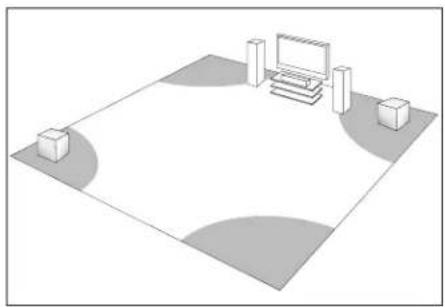
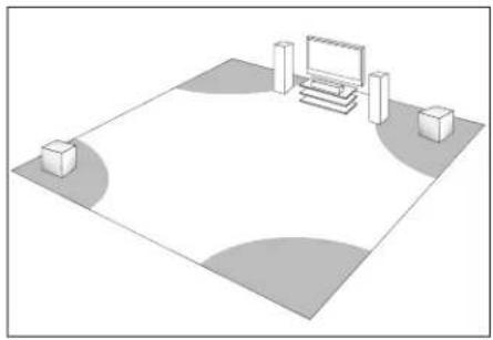
THE ADVANTAGES OF USING TWO SUBWOOFERS
Although a single Paradigm subwoofer provides exceptional performance and substantial output, the quality (and quantity) of bass can be further improved with the use of two subwoofers (Fig. 2). This allows you to randomize the standing waves within your listening room so that bass will be distributed in a more uniform manner. Two subwoofers also provide even lower distortion, especially at high output levels.
Wireless Subwoofers
Keep in mind that when using two wireless PDR-W100 subwoofers, one wireless transmitter is required per subwoofer.
(See Dealer for connection instructions using multiple subwoofers.)
USING TWO SUBWOOFERS IN YOUR LISTENING ROOM
When using two subwoofers, placing one in the front of the room and the other in the rear of the room (as shown in Fig. 2) usually provides the best bass performance and sonic integration. Consult the fine tuning section of the Owner's Manual for more information on adjusting phase settings. If those locations are not possible or if you want to experiment with placement options using two subwoofers, the following procedure will be a helpful guide to achieving better bass performance. Refer to the section on 'Subwoofer Connection,' then proceed as follows:
- Temporarily turn all speakers off (either by turning your amplifier off or disconnecting them);
-
Connect and place one subwoofer in the central area of your listening room. Follow directions for connection, as outlined in the appropriate section;
-
At a moderately loud level, play music or a video soundtrack with extended bass that is repetitive or continuous;
- Walk around your room and note where the bass sounds louder and where it sounds quieter;
- Place the first subwoofer within a louder bass area of your room; then place the second subwoofer within a quieter bass area of your room;
- Connect both subwoofers and switch all speakers back on; switch the amplifier on, or reconnect it;
- Follow the 'Fine Tuning' instructions later in this manual, to optimize your system's overall bass performance.
NOTE: The preceding is only a guideline. You may want to use a bass test disc and SPL meter to more accurately determine the bass characteristics of your listening room (see Dealer for more information). Remember that room
acoustics vary so it may take some experimenting with placement to achieve the best subwoofer performance.
If you are not using a wireless option on your subwoofer (selected models only) skip this section
WIRELESS OPERATION
Subwoofer placement plays a major role in optimizing bass performance. However, placement can impose the inconvenience, not to mention the unsightliness, of running long lengths of cable through walls, along baseboards and under floors and carpets. Going wireless means you no longer have to worry about placement while cable clutter becomes a thing of the past. Actual system setup time is often drastically reduced with the wireless option.
Transmitter Operation
In a typical listening room your new wireless transmitter has a maximum range of 50' (15 m). Obstructions such as walls, large pieces of furniture, room dividers, etc., may reduce transmitter range. Do not place subwoofer and transmitter farther apart than the recommended range. We do not recommend installing your transmitter in another room. The transmitter's compact dimensions allow it to fit neatly into a standard audio/video rack.
Your wireless transmitter features a 2.4 GHz uncompressed digital self-sensing design that will automatically adjust for the best wireless connection while monitoring the integrity of the data stream.
An RCA audio cable is required (not included) to connect the transmitter to your A/V receiver or preamplifier. (See Dealer for cable recommendations.) One transmitter is required for each wireless subwoofer in operation.
WARNING: To prevent signal dropouts or interference, keep the transmitter well out of range of a microwave oven, mobile telephone or Bluetooth device operating on the same frequency.
IMPORTANT! The transmitter that is included with your wireless-ready Paradigm PDR subwoofer is not compatible with any other subwoofer brand. Before connecting your new subwoofer, you must establish a permanent connection between the transmitter and subwoofer by 'pairing' the two. See below for more details ...
'PAIRING' YOUR WIRELESS SUBWOOFER WITH THE TRANSMITTER
- Plug subwoofer into wall (not shown) and using the toggle switch on the back panel, turn it on (ON or AUTO setting). Wait for the back-panel 'STATUS' LED to flash Red slowly.
- Plug transmitter into wall, the LED will also flash Red slowly.
- Press and hold 'Pair' button on transmitter for 3 to 5 seconds until the transmitter's front-panel LED begins to flash Red quickly. Release button.
- Press and release 'Pair' button on back panel of subwoofer.
Permanent connection has been established when LEDs on both transmitter and subwoofer glow solid Red. Typically, the pairing process is permanent.
If for some reason you do have to 'pair' transmitter and subwoofer again, simply follow this 4-step process.
SUBWOOFER CONNECTION (all models)

SAFETY PRECAUTION: Before proceeding with this section be sure to read and follow all safety precaution and instruction notices at the beginning of this manual.
We recommend the use of high-quality cables and connectors when hooking up your subwoofer (see Dealer for more information).


Turn all components OFF before connecting the subwoofer.
CONNECTION OPTIONS — Wired Subwoofer
Before connecting your wired subwoofer, please read this section to determine which setup option best suits your needs. (See Dealer if you require additional information.)
a) Line-Level Input From Sub/LFE Output (Fig. 3) – For use with a receiver or processor that has a Sub-Out/ LFE-Out jack.
Using an RCA-to-RCA interconnect cable (not included) connect the subwoofer as shown. If your subwoofer has two low-level input jacks use the right (LFE) input.
b) Line-Level Input From Pre-Out/Front-Out Without High-Pass Output from Sub (Fig. 4) – For use with a processor/preamp and amplifier, or receiver with Pre-Out/Front-Out and Main-In jacks.
Using RCA-to-RCA interconnect cables and 'Y' splitters (not included) connect the subwoofer as shown.
CONNECTION OPTIONS — Wireless Subwoofer
Before connecting your wireless transmitter to receiver or preamp/processor, ensure you have "paired" subwoofer and transmitter, (refer back to previous section).
a) Line-Level Input From Sub/LFE Output (Fig. 5) – For use with a receiver or processor that has a Sub-Out/LFE-Out jack.
Using an RCA-to-RCA interconnect cable (not included) connect the transmitter as shown.
b) Line-Level Input From Pre-Out/Front-Out Without High-Pass Output from Sub (Fig. 6) – For use with a processor/preamp and amplifier, or receiver with Pre-Out/Front-Out and Main-In jacks.
Using RCA-to-RCA interconnect cables and 'Y' splitters (not included) connect transmitter as shown.
FINE TUNING
Once you have the rest of your speakers positioned in the room and have set speaker distances and calibrated speaker levels with your Processor or A/V Receiver, it's time for a little fine tuning of the subwoofer(s).
Subwoofer Controls
When setting the subwoofer controls use music and video soundtracks that you know well. They should contain selections with extended bass that is continuous and repetitive. When you are adjusting your subwoofer, remember: Bass should not be overbearing—the subwoofer should not draw attention to itself—but sound shouldn't be 'thin' or difficult to hear.
Certain subwoofer placement may result in bass frequency cancellations—this occurs when your front speakers and subwoofer are 'out-of-phase', in other words, they work against each other through the crossover region. This will result in bass being reduced. If bass sounds weak or dislocated adjust the phase according to the instructions that apply to your subwoofer in the setup procedures that follow.
SETTING SUBWOOFER CONTROLS
- Turn the Subwoofer Level control completely counter-clockwise to its minimum;
- Turn the Subwoofer Cut-Off Frequency control to 'Bypass';
- Set the Phase Switch to 0°;
NOTE: When using receivers with Automatic Level and Crossover setting systems such as Anthem's ARC system, the Volume Level should be set to 'Detent' (center), Phase should be set to '0' and Crossover set to 'Bypass,' then skip the next four steps.
-
While you listen to a selection in your primary listening area, have an assistant turn up the Subwoofer Level control until the subwoofer can be clearly heard;
-
Have your assistant try the Phase Control Switch in both positions until you determine which one delivers the most bass. Your subwoofer and front speakers are now 'in phase.' Do not change phase switch again unless you move your subwoofer or front speakers;
-
Turn the Subwoofer Level control completely counter-clockwise to its minimum;
- Turn the Subwoofer Cut-Off Frequency control completely counterclockwise to 50 Hz;
- Slowly rotate the Subwoofer Level control until you match the subwoofer output level with the level of your front speakers. Bass should be clearly audible, but not intrusive;
- Slowly rotate the Subwoofer Cut-Off Frequency control until you hear the best subwoofer/main speaker blend. If the sound is too 'thin,' you have not set the frequency high enough; if the sound becomes 'boomy' you have set the frequency too high. Adjust until you find the most natural balance.
SPECIFICATIONS
| PDR-80 PDR-100 | PDR-W100 (wireless model) | ||
| Design | Single driver, bass reflex, high-velocity low-turbulence port, built-in amplifier | Single driver, bass reflex, high-velocity low-turbulence port, built-in amplifier | Single driver, bass reflex, high-velocity low-turbulence port, built-in amplifier |
| Amplifier: High-Current, Discreet Output | 300 watts Dynamic Peak/ 100 watts RMS Sustained | 360 watts Dynamic Peak/ 120 watts RMS Sustained | 360 watts Dynamic Peak/ 120 watts RMS Sustained |
| Amplifier Design Features | Auto-On/Standby, soft clipping | Auto-On/Standby, soft clipping | Auto-On/Standby, soft clipping |
| Bass Driver | 210-mm (8 in) reinforced polymer-composite cone, 35.5-mm (1-1/2 in) voice-coil | 254-mm (10 in) reinforced polymer-composite cone, 38-mm (1-1/2 in) voice coil | 254-mm (10 in) reinforced polymer-composite cone, 38-mm (1-1/2 in) voice coil |
| Low-Frequency Extension* | 32 Hz (DIN) | 29 Hz (DIN) | 29 Hz (DIN) |
| Subwoofer Cut-Off Frequency | Variable 50 Hz – 150 Hz; Bypass option | Variable 50 Hz – 150 Hz; Bypass option | Variable 50 Hz – 150 Hz; Bypass option |
| Sub/Sat Phase Alignment | 0° or 180° | 0° or 180° | 0° or 180° |
| Line-Level Inputs | Two RCA (L/R-Mono) for L/R line out or Sub-Out/LFE-Out of receiver/processor or other line-level source | Two RCA (L/R-Mono) for L/R line out or Sub-Out/LFE-Out of receiver/processor or other line-level source | Two RCA (L/R-Mono) for L/R line out or Sub-Out/LFE-Out of receiver/processor or other line-level source |
| Height, Width, Depth (height includes feet; depth includes grille and amplifier) | 35.6 cm x 30.5 cm x 36.2 cm 14 in x 12 in x 14-6/16 in | 39.4 cm x 33.3 cm x 38.7 cm 15-1/2 in x 13-2/16 in x 15-1/4 in | 39.4 cm x 33.3 cm x 38.7 cm 15-1/2 in x 13-2/16 in x 15-1/4 in |
| Weight (unpacked) | 10.9 kg/24 lb each | 13.2 kg/29 lb each | 13.2 kg/29 lb each |
| Finish | Black Ash | Black Ash | Black Ash |
| RF Frequency (wireless model) | n/a | n/a | 2.4 GHz |
| Latency (ms) | n/a | n/a | 13 ms |
| Transmission Range (ft/m) | n/a | n/a | 15 meters (50 ft) |
| Sampling Frequency /# bits | n/a | n/a | 48 kHz, 16 bits |
| Compression | n/a | n/a | No compression |
* DIN 45 500. Indicates -3 dB in a typical listening room.
LIMITED WARRANTY
Paradigm ^® subwoofers covered in this manual are warranted to be and remain free of manufacturing and/or material defects for a period of three (3) years from the date of the original retail purchase. For subwoofers with a wireless option, the included transmitter is also warranted to be and remain free of manufacturing/and or material defects for a period of three (3) years from the date of the original retail purchase.
Within the time period specified, repair, replacement or adjustment of parts for manufacturing and/or material defects will be free of charge to the original owner.
Thermal or mechanical abuse/misuse is not covered under warranty.
Limitations:
- Warranty begins on date of original retail purchase from an Authorized Paradigm Dealer only. It is not transferable;
- Warranty applies to product in normal home use only. If the product is subjected to any of the conditions outlined in the next section, warranty is void;
- Warranty does not apply if the product is used in professional or commercial applications.
Warranty is Void if:
- The product has been abused (intentionally or accidentally);
- The product has been used in conjunction with unsuitable or faulty equipment;
-
The product has been subjected to damaging signals, derangement in transport, mechanical damage or any abnormal conditions;
-
The product (including cabinet) has been tampered with or damaged by an unauthorized service facility;
- The serial number has been removed or defaced.
Owner Responsibilities:
- Provide normal/reasonable operating care and maintenance;
- Provide or pay for transportation charges for product to service facility;
- Provide proof of purchase (your sales receipt given at time of purchase from your Authorized Paradigm Dealer).
Should servicing be required, contact your nearest Authorized Paradigm Dealer, Paradigm Electronics Inc., or Import Distributor (outside the U.S. and Canada) to arrange, bring in or ship prepaid any defective unit. Visit our website at www.paradigm.com for more information.
Paradigm Electronics Inc. reserves the right to improve the design of any product without assuming any obligation to modify any product previously manufactured.
This warranty is in lieu of all other warranties expressed or implied, of merchantability, fitness for any particular purpose and may not be extended or enlarged by anyone. In no event shall Paradigm Electronics Inc., their agents, or representatives be responsible for any incidental or consequential damages. Some jurisdictions do not allow limitation of incidental or consequential damages, so this exclusion may not apply to you.
Retain this manual and your sales receipt for proof of warranty term and proof of purchase.
Paradigm MD
LE SUMMUM EN QUALITÉ SONORE POUR LA MUSIQUE ET LE CINÉMA MAISON ^TM

natural_image
Black-and-white photo of a woman sitting in a modern chair with a speaker nearby (no text or symbols visible)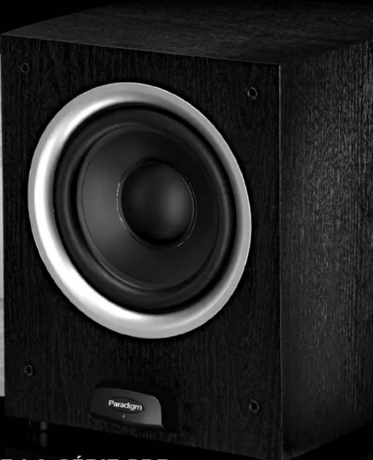
natural_image
Close-up of a wooden speaker with concentric sound waves, no visible text or symbols on the device body.CAISSON DE SOUS-GRAVES DE LA SÉRIE PDR MODE D'EMPLOI


Raccorder du caisson (illustration) 6
natural_image
Simple 3D diagram of a rectangular plane with a small cube on top, surrounded by shaded circular regions (no text or symbols)Fig. 1a
natural_image
3D diagram of a rectangular grid with a small cube on top, no text or symbols presentFig. 1b Fig. 2
natural_image
Simple 3D diagram of a rectangular area with a central monitor and two side blocks, no text or symbols present.
natural_image
Simple 3D diagram of a rectangular area with a central monitor and two side blocks, no text or symbols present.RACCORDEMENT DU CAISSON
Étape 3
Étape 4


- TABLE OF CONTENTS
- RECYCLING AND REUSE GUIDELINES FOR EUROPE
- SAFETY PRECAUTIONS
- READ THIS SECTION CAREFULLY BEFORE PROCEEDING!
- WARNING
- IMPORTANT SAFETY INSTRUCTIONS
- BACK PANEL: CONTROLS AND CONNECTIONS
- BACK PANEL: CONTROLS AND CONNECTIONS (continued)
- SUBWOOFER PLACEMENT (Additional details in text section Subwoofer Placement)
- CONNECTING YOUR SUBWOOFER (Additional details in text section Connecting Your Subwoofer)
- 'PAIRING' YOUR WIRELESS SUBWOOFER WITH THE TRANSMITTER
- What do the blinking LEDs mean on Subwoofer and Transmitter?
- YOUR NEW SUBWOOFER
- Break-In
- Cleaning
- POWER REQUIREMENTS
- ROOM ACOUSTICS
- SUBWOOFER PLACEMENT
- THE ADVANTAGES OF USING TWO SUBWOOFERS
- Wireless Subwoofers
- USING TWO SUBWOOFERS IN YOUR LISTENING ROOM
- If you are not using a wireless option on your subwoofer (selected models only) skip this section
- WIRELESS OPERATION
- Transmitter Operation
- SUBWOOFER CONNECTION (all models)
- CONNECTION OPTIONS — Wired Subwoofer
- CONNECTION OPTIONS — Wireless Subwoofer
- FINE TUNING
- Subwoofer Controls
- SETTING SUBWOOFER CONTROLS
- LIMITED WARRANTY
- Thermal or mechanical abuse/misuse is not covered under warranty.
- Limitations:
- Warranty is Void if:
- Owner Responsibilities:
- Paradigm MD
- CAISSON DE SOUS-GRAVES DE LA SÉRIE PDR MODE D'EMPLOI
- RACCORDEMENT DU CAISSON
Brand : Paradigm
Model : PDR 80
Category : Subwoofer