
PSP5W - Speaker stands Peerless-AV - Free user manual and instructions
Find the device manual for free PSP5W Peerless-AV in PDF.
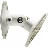
| Product Type | Wall/Ceiling Speaker Mount |
| Brand | Peerless-AV |
| Model | PSP5W |
| Color | White |
| Maximum Load Capacity | 3.62 kg (8 lb) |
| Number of Speakers Supported | 5 (sold in pack of 5) |
| Material | Steel with painted finish |
| Mounting Type | Wall or ceiling (with provided extensions) |
| Orientation | Pivot and swivel for optimal positioning |
| Wall Fixing | On wood studs, concrete, concrete blocks, or drywall (with provided anchors) |
| Included Screws | M5, 8-32, 1/4-20, M4, self-tapping, etc. |
| Required Tools | Phillips screwdriver, drill, level, tape measure, stud finder |
| Safety | Do not exceed max load; installation by competent person; verify support solidity |
| Maintenance | Clean with a soft dry cloth; do not use abrasive products |
| Warranty | Consult manufacturer |
| Spare Parts | Contact Peerless-AV customer service |
Frequently Asked Questions - PSP5W Peerless-AV
User questions about PSP5W Peerless-AV
0 question about this device. Answer the ones you know or ask your own.
Ask a new question about this device
Download the instructions for your Speaker stands in PDF format for free! Find your manual PSP5W - Peerless-AV and take your electronic device back in hand. On this page are published all the documents necessary for the use of your device. PSP5W by Peerless-AV.
USER MANUAL PSP5W Peerless-AV
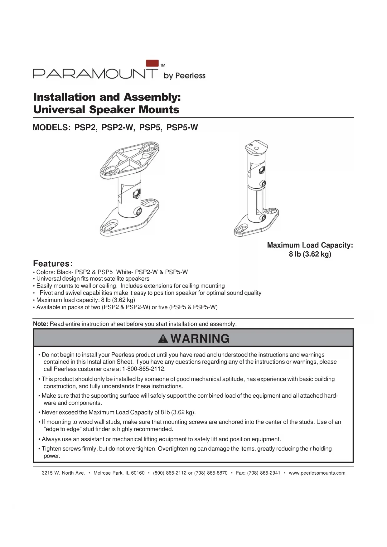
Installation and Assembly: Universal Speaker Mounts
MODELS: PSP2, PSP2-W, PSP5, PSP5-W
Maximum Load Capacity: 8 lb (3.62 kg)
Features:
- Colors: Black-PSP2 & PSP5 White-PSP2-W & PSP5-W
Universal design fits most satellite speakers - Easily mounts to wall or ceiling. Includes extensions for ceiling mounting
- Pivot and swivel capabilities make it easy to position speaker for optimal sound quality
Maximum load capacity: 8 lb (3.62 kg)
Available in packs of two (PSP2 & PSP2-W) or five (PSP5 & PSP5-W)
Note: Read entire instruction sheet before you start installation and assembly.
WARNING
- Do not begin to install your Peerless product until you have read and understood the instructions and warnings contained in this Installation Sheet. If you have any questions regarding any of the instructions or warnings, please call Peerless customer care at 1-800-865-2112.
This product should only be installed by someone of good mechanical aptitude, has experience with basic building construction, and fully understands these instructions. - Make sure that the supporting surface will safely support the combined load of the equipment and all attached hardware and components.
- Never exceed the Maximum Load Capacity of 8 lb (3.62 kg).
- If mounting to wood wall studs, make sure that mounting screws are anchored into the center of the studs. Use of an "edge to edge" stud finder is highly recommended.
- Always use an assistant or mechanical lifting equipment to safely lift and position equipment.
- Tighten screws firmly, but do not overtighten. Overtightening can damage the items, greatly reducing their holding power.
Tools Needed for Assembly
- stud finder ("edge to edge" stud finder is recommended)
- phillips screwdriver
drill - 1/8" bit for wood stud wall
- 5/16" bit for concrete and cinder block wall
- level
- tape measure
Before you begin, make sure all parts shown are included with your product. Parts may appear slightly different than illustrated.
| Parts List | PSPK2 PSPK5 PSPK2-W PSPK5-W | ||
| Description Qty. | Qty. | ||
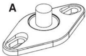
| A double hole mounting plate | 4 | 10 | |
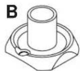
| B single hole mounting plate | 2 | 5 | |
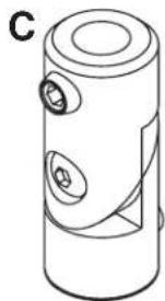
| C arm | 2 | 5 | |
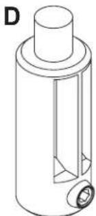
| D arm extension | 2 | 5 | |
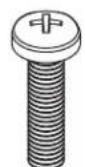
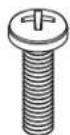
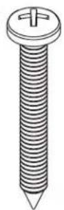
| E M5 x 20 mm phillips screw | 2 | 5 | |
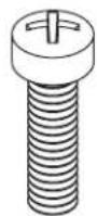
| F 8-32 x 5/8" phillips screw | 2 | 5 | |
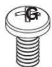
| G 1/4"-20 x 7/8" phillips screw | 2 | 5 | |
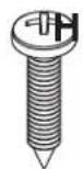
| H M4 x 8 mm flat head phillips screw | 2 | 5 | |
| I M5 x 1/8" plastic washer | 2 | 5 | |
| J 8-32 round key hole nut | 2 | 5 | |
| K 1/4"-20 x 1/2" phillips screw | 4 | 10 | |
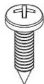
| L #8 x 3/4" self tapping screw | 2 | 5 | |
| M #12 x 3/4" self tapping screw | 4 | 10 | |
| N #12 x 1-3/4" self tapping screw | 4 | 10 | |
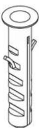
| O #12-14 Alligator concrete anchor | 4 | 10 | |
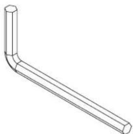
| P allen wrench | 1 | 1 | |


N
0
P
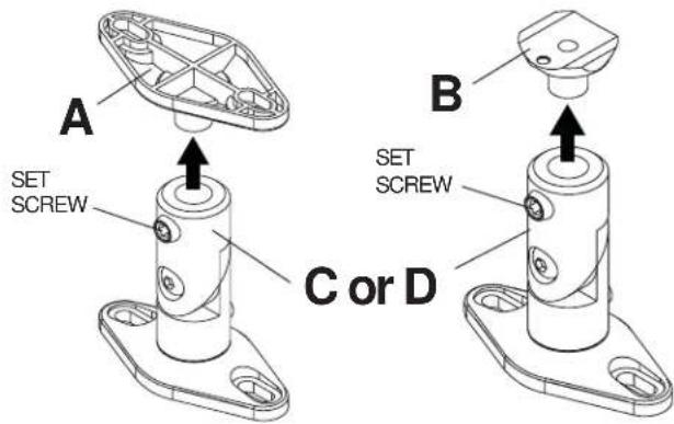
Remove Mounting Plate

Satellite speakers may require either the single hole mounting plate (B) or the double hole mounting plate (A). Remove mounting plates (if attached) from arm (C or D) by disengaging the hex set screws a few turns using the allen wrench (P). Pull mounting plates (A or B) from arm.
NOTE: Speaker mounts may come preassembled in different configurations.
Installing Mounting Plate to Speaker

Single hole threaded insert mounting
Confirm the hole size on back of speaker can use either of the following screws: 8 - 32 × 5 / 8 screw (F), M5 x 20 mm Phillips screw (E), 1 / 4 - 20 × 7 / 8 phillips screw (G) or M4 x 8 mm flat head phillips screw (H).
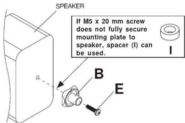
For attachment to speakers with M5 threaded insert:
Attach single hole mounting plate (B) to back of speaker using M5 x 20 mm screw (E) as shown.
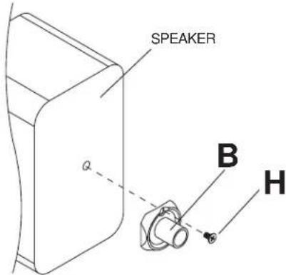
For attachment to speakers with M4 threaded insert:
Attach single hole mounting plate (B) to back of speaker using M4 × 8 mm flat head phillips screw (H) through the off-center hole on mounting plate as shown.
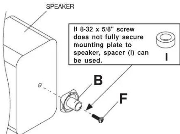
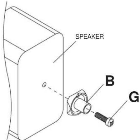
For attachment to speakers with 8-32 threaded insert:
Attach single hole mounting plate (B) to back of speaker using 8 - 32× 5 / 8 phillips screw (F) as shown.
For attachment to speakers with 1/4"-20 threaded insert:
Attach single hole mounting plate (B) to back of speaker using 1/4 - 20 × 7/8 phillips screw (G) as shown.
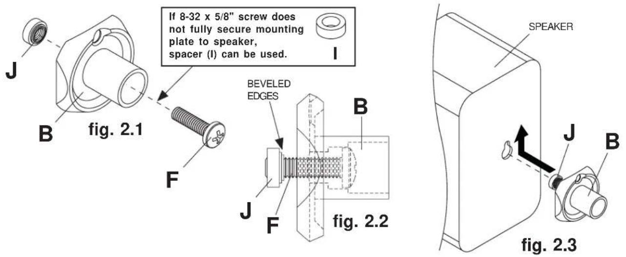
2-1 Single Keyhole Mounting
Insert 8 - 32 × 5 / 8 " phillips screw (F) through the single hole mounting plate (B) and thread the 8-32 round key hole nut (J) a few turns onto the 8 - 32 × 5 / 8 " phillips screw as shown in figure 2.1 and figure 2.2. Be certain beveled edges of round key hole nut face mounting plate. Do not fully secure 8-32 round key hole nut at this time. Insert 8-32 round key hole nut into the key hole slot of speaker and slide upward into narrow end of key hole as shown in figure 2.3. Secure mounting plate to speaker by gently pulling back on mounting plate and tighten 8 - 32 × 5 / 8 " phillips screw.
2-2 Two-hole or Four-hole Mounting
Attach double hole mounting plate (A) to speaker using two 1/4 - 20 × 1/2 screws (K) as shown in figure 2.4. Four-hole speaker mount patterns can be accommodated by positioning the mounting plate diagonally as shown in figure 2.5.
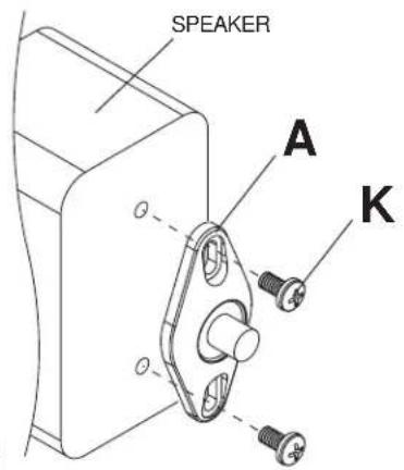
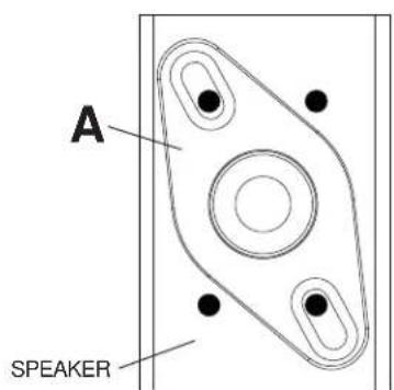
fig. 2.4
fig. 2.5
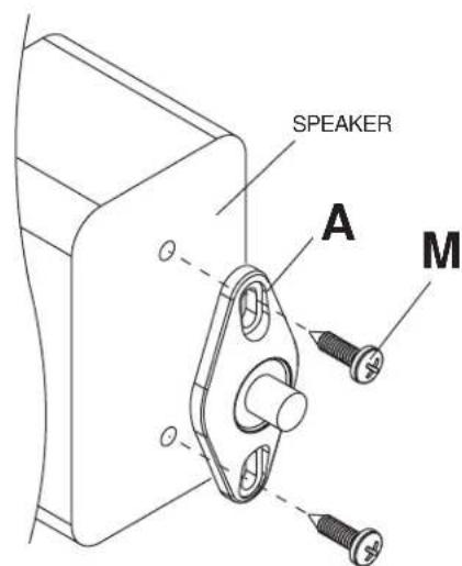
2-3 Self-Tapped Mounting
Position double hole mounting plate (A) on back of speaker in mounting location and use it as a template to mark center of holes. Drill two pilot 1/8'' (3 mm) dia. holes .5" (12 mm) deep. Do not drill deeper than .5".
CAUTION
- Do not drill or screw into the speaker where you could possibly damage the internal components. If unsure of location of internal components, check specifications with manufacturer of the speaker.
Secure mounting plate to speaker with two #12 x 3/4" self tapping screws (M).
Installing Mounting Plate to Wall or Ceiling

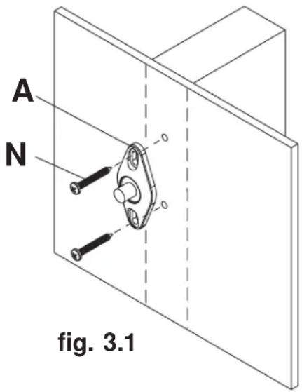
For Attachment to Wood Studs or Wood Beams
Use a stud finder to locate the edges of the stud. Use of an edge-to-edge stud finder is highly recommended. Based on their edges, draw a vertical line down the stud's center. Place mounting plate (A) on wall as a template. Mark the center of the two mounting holes. Make sure the mounting holes are on the stud centerline. Drill four 1/8'' (3 mm) dia. holes 1-7/8'' (48 mm) deep. Secure mounting plate using two #12 x 1-3/4" self tapping screws (N).
3-1 For Attachment to Concrete or Cinder Block
Use mounting plate as a template to mark the two mounting holes. NOTE: For wall mounting applications, position mounting holes in a vertical pattern. Drill two 5 / 16" (8 mm) dia. holes to a minimum depth of 1-7/8" (48 mm). Insert anchors (O) in holes flush with surface as shown in figure 3.2. Place mounting plate over anchors and secure with two #12 x 1-3/4" self tapping screws (N) as shown in figure 3.3.
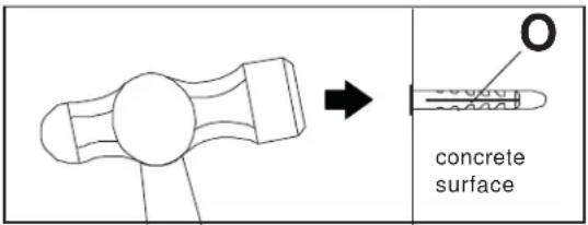
fig. 3.2
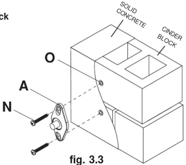
fig. 3.3
WARNING
- When installing Peerless wall mounts on cinder block, verify that you have a minimum of 1 - 5 / 8 of actual concrete surface in the 1 / 4 diameter hole to be used for the concrete anchors. It is suggested that a standard electric drill on slow setting is used to drill the hole instead of a hammer drill to avoid breaking out the back of the hole when entering a void or cavity. Do not drill into mortar joints!
- Never attach concrete expansion anchors to concrete covered with plaster, drywall or other finishing material. If mounting to concrete surfaces covered with a finishing surface is unavoidable, the finishing surface must be counterbored.
- Tighten concrete anchor bolt firmly, but do not overtighten. Overtightening can damage the screw, greatly reducing its holding power.
- Never tighten in excess of 80 in - lb (9 N.M.).
3-2 For Attachment to Drywall surface
Use mounting plate (A) as a template to mark the two mounting holes. NOTE: In wall mounting applications position mounting holes in a vertical pattern. Drill two 5 / 16'' (8mm) dia. holes through drywall. Insert anchors (O) in holes flush with drywall as shown in figure 3.4. Place mounting plate over anchors and secure with two #12 x 1-3/4" self tapping screws (N).
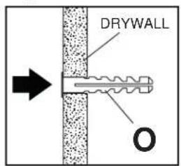
fig. 3.4
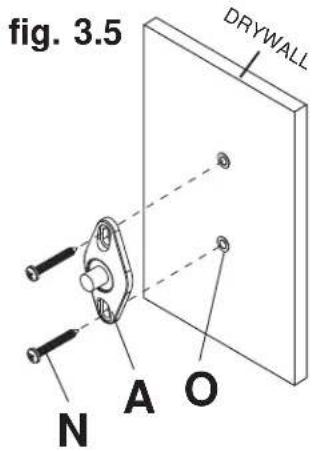
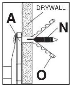
fig. 3.6
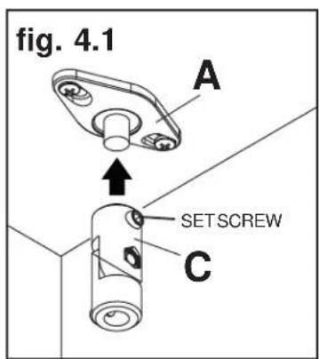
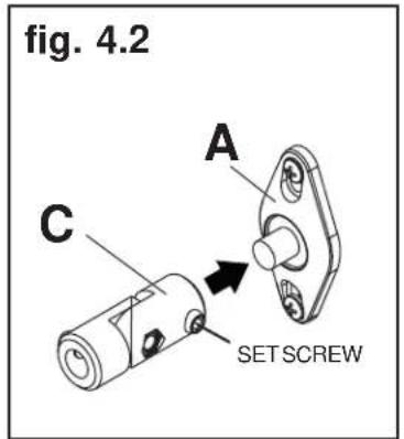
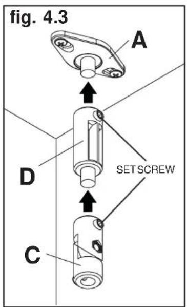
Installing Arms to Mounting Plate

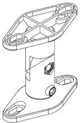
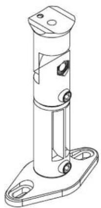
Insert arm (C) or extension arm (D) onto mounting plate attached to surface as shown in figure 4.1 or 4.2. Extension arm can be used with arm as shown in figure 4.3. Tighten set screws with allen wrench (P).
NOTE: Extension arm is not recommended with wall mounted applications.
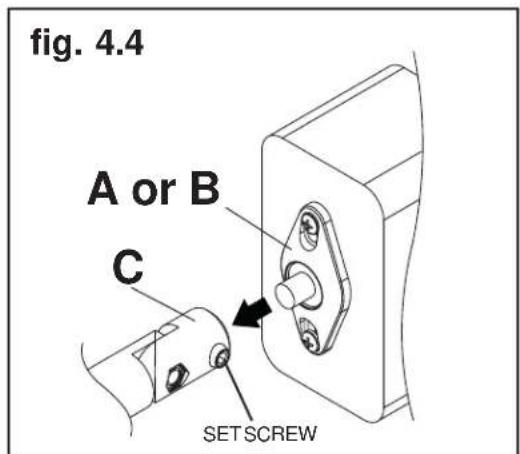
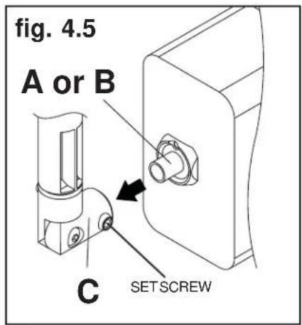
Insert mounting plate (A or B) attached on speaker into arm (C). Tighten set screw with allen wrench (P) as shown in figure 4.4 or 4.5.
- Installation and Assembly: Universal Speaker Mounts
- Features:
- WARNING
- Tools Needed for Assembly
- Remove Mounting Plate
- Installing Mounting Plate to Speaker
- Single hole threaded insert mounting
- For attachment to speakers with M5 threaded insert:
- For attachment to speakers with M4 threaded insert:
- For attachment to speakers with 8-32 threaded insert:
- For attachment to speakers with 1/4"-20 threaded insert:
- 2-1 Single Keyhole Mounting
- 2-2 Two-hole or Four-hole Mounting
- 2-3 Self-Tapped Mounting
- CAUTION
- Installing Mounting Plate to Wall or Ceiling
- For Attachment to Wood Studs or Wood Beams
- 3-1 For Attachment to Concrete or Cinder Block
- 3-2 For Attachment to Drywall surface
- Installing Arms to Mounting Plate
Brand : Peerless-AV
Model : PSP5W
Category : Speaker stands