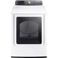
USER MANUAL DV48J7770EW SAMSUNG
What you need to know about the safety instructions 4
Important safety symbols 4
Important safety precautions 5
Installation 10
What's included 10
Before installation 12
Basic requirements 12
Location considerations 13
Ducting requirements 14
Exhausting 16
Gas requirements 17
Electrical requirements 18
Grounding 19
Electrical connections 20
Step-by-step installation 21
Connecting the inlet hose 26
Final installation check list 28
Vent blockage test (DV48J7700E(G)*) 29
Dryer exhaust tips 30
Door reversal 33
Before you start 36
Guideline 36
Operations 37
Control panel 37
Simple steps to start 40
Cycle overview 41
Cycle guide 43
Options 44
Maintenance 46
Vent Sensor (DV48J7770E(G)*) 46
Cleaning 47
2 English
Troubleshooting 48
Checkpoints
Information codes 51
48
Specifications 53
Protecting the environment 53
Specification sheet 54
Cycle chart 56
Congratulations on your new Samsung dryer. This manual contains important information on the installation, use and care of your appliance. Please take some time to read this manual to take full advantage of your dryer's many benefits and features.
What you need to know about the safety instructions
Please read this manual thoroughly to ensure that you know how to safely and efficiently operate the extensive features and functions of your new appliance. Please store the manual in a safe location close to the appliance for future reference. Use this appliance only for its intended purpose as described in this instruction manual.
Warnings and Important Safety Instructions in this manual do not cover all possible conditions and situations that may occur. It is your responsibility to use common sense, caution and care when installing, maintaining and operating your dryer.
Because the following operating instructions cover various models, the characteristics of your dryer may differ slightly from those described in this manual and not all warning signs may be applicable. If you have any questions or concerns, contact your nearest service center or find help and information online at www.samsung.com.
Important safety symbols
What the icons and signs in this user manual mean:

WARNING
Hazards or unsafe practices that may result in severe personal injury, death and/or property damage.

CAUTION
Hazards or unsafe practices that may result in personal injury and/or property damage.

NOTE
Indicates that a risk of personal injury or material damage exists.
SAVE THESE INSTRUCTIONS
4 English
These warning signs are here to prevent injury to yourself and others.
Please follow them explicitly.
After reading this manual, store it in a safe place for future reference.
Read all instructions before using the appliance.
As with any equipment that uses electricity and moving parts, potential hazards exist. To safely operate this appliance, familiarize yourself with its operation and exercise care when using it.

WARNING - Gas Appliances:
• State of California Proposition 65 Warnings (US only)
This product contains chemicals known to the State of California to cause cancer and birth defects or other reproductive harm.
- Gas appliances can cause low-level exposure to Proposition 65 listed substances, including but not limited to, benzene, carbon monoxide, formaldehyde and soot, substances resulting from the incomplete combustion of natural gas or LP fuels.

WARNING - Risk of Fire
• Clothes dryer installation must be performed by a qualified installer.
• Install the clothes dryer according to the manufacturer's instructions and local codes.
- Do not install a clothes dryer with flexible plastic venting materials. If flexible metal (foil type) duct is installed, it must be of a specific type identified by the appliance manufacturer as suitable for use with clothes dryers. Flexible venting materials are known to collapse, be easily crushed, and trap lint. These conditions will obstruct clothes dryer airflow and increase the risk of fire.
• To reduce the risk of severe injury or death, follow all installation instructions.
- Save these instructions.
Important safety precautions

WARNING
To reduce the risk of fire, electric shock, or injury to persons when using your appliance, follow basic precautions, including the following:
SAVE THESE INSTRUCTIONS
English
- Read all instructions before using this appliance.
- Do not dry articles that have been previously cleaned in, washed in, soaked in, or spotted with gasoline, dry-cleaning solvents, or other flammable or explosive substances, as they give off vapors that could ignite or explode.
- Do not use the dryer to dry clothes which have traces of any flammable substance, such as vegetable oil, cooking oil, machine oil, flammable chemicals, paint thinner, etc., or anything containing wax or chemicals, such as mops and cleaning cloths. Flammable substances may cause the fabric to catch fire by itself.
- Do not store or use gasoline or other flammable vapors and liquids near this or any other appliance.
- Do not allow children to play on or in the appliance. Close supervision of children is necessary when the appliance is used near children.
- Before the appliance is removed from service or discarded, remove the door to the drying compartment.
- Do not reach into the appliance if the drum is moving.
- Do not install or store this appliance where it will be exposed to the weather.
- Do not tamper with internal controls.
- Do not repair or replace any part of the appliance or attempt any service unless specifically recommended in the user-maintenance instructions or in published userrepair instructions that you understand and have the skills to carry out.
- Do not use fabric softeners or products to eliminate static unless recommended by the manufacturer of the fabric softener or product.
- Clean the lint screen before or after each load.
- Do not use heat to dry articles containing foam rubber or similarly textured rubber-like materials.
- Keep area around the exhaust opening and adjacent surrounding areas free from the accumulation of lint, dust, and dirt.
- The interior of the appliance and exhaust duct should be cleaned periodically by qualified service personnel.
- Do not place items exposed to cooking oils in your dryer. Items contaminated with cooking oils may contribute to a chemical reaction that could cause a load to catch fire.
- This appliance must be grounded. See "Electrical requirements" and "Grounding" in "Installation" section.
- Do not allow children to play on or in the appliance. Close supervision of children is necessary when the appliance is used near children.
- Do not insert your hand under the dryer.
SAVE THESE INSTRUCTIONS
6 English
• This may result in injury.
- Take care that children's fingers are not caught in the door when closing it.
• This may result in injury.
- Control board and inlet valve are intentionally not grounded and may present a risk of electric shock only during servicing.
- Do not contact this part while appliance is energized.
WARNING - To reduce the risk of fire or explosion:
- Do not dry items that have been previously cleaned, washed, soaked, or spotted with gasoline, dry cleaning solvents, or other flammable or explosive substances. They emit vapors that could ignite or explode. Any material that has been in contact with a cleaning solvent or flammable liquids or solids should not be placed in the dryer until all traces of these flammable liquids or solids and their fumes have been removed.
There are many highly flammable items used in homes, such as acetone, denatured alcohol, gasoline, kerosene, some liquid household cleaners, some spot removers, turpentine, wpees, and wpe removers.
- Items containing foam rubber (may be labeled latex foam) or similarly textured rubberlike materials must not be dried on a heat setting. Heated foam rubber materials can, under certain circumstances, produce fire by spontaneous combustion.
WARNING - What to do if you smell gas:
• Do not try to light any appliance.
• Do not turn on the appliance.
- Do not touch any electrical switch.
- Do not use any phone in your building.
• Clear the room, building or area of all occupants.
- Immediately call your gas supplier from a neighbor's phone. Follow the gas supplier's instructions.
• If you cannot reach your gas supplier, call the fire department.
- Installation and service must be performed by a qualified installer, service agency, or the gas supplier.
SAVE THESE INSTRUCTIONS
English
Warnings

WARNING
Ensure pockets are free from small, irregularly shaped hard objects, foreign material, etc. ie. coins, knives, pins, etc. These objects could damage your dryer.
Gas leaks may occur in your system, resulting in a dangerous situation.
Cautions

CAUTION
Do not allow children or pets to play on, in, or in front of the appliance. Close supervision is necessary when the appliance is used near children and pets.
Before discarding or removing your dryer from service, remove the door to the drying compartment to prevent children or animals from becoming trapped inside.
Do not reach into the appliance when the drum is moving.
Do not install or store this appliance where it will be exposed to the weather.
Do not tamper with controls.
Do not repair, replace, or attempt to service any part of the appliance unless specifically instructed to in the user-repair instructions and you have the understanding and skills to carry out the procedure.
Do not use fabric softeners or products to eliminate static unless the softener or product is recommended for dryer use by the manufacturer of the fabric softener or product.
Clean the lint screen before or after each load.
Keep the area around the exhaust opening and surrounding areas free from lint, dust, and dirt.
The interior of the dryer and exhaust duct should be cleaned periodically by qualified service personnel.
SAVE THESE INSTRUCTIONS
8 English
This appliance must be properly grounded. Never plug the power cord into a receptacle that is not grounded adequately or not in accordance with local and national codes. See installation instructions for information about grounding this appliance.
Do not sit on top of the dryer.
Do not wash clothing with large buckles, buttons, or other heavy metal or solid objects.
Gas leaks may not be detected by smell alone.
Gas suppliers recommend you purchase and install a UL-approved gas detector.
Install and use in accordance with the manufacturer's instructions.
Do not place items in your dryer that have been spotted or soaked with vegetable oil or cooking oil. Even after being washed, these items may contain significant amounts of these oils.
Residual oil on clothing can ignite spontaneously. The potential for spontaneous combustion increases when items containing vegetable oil or cooking oil are exposed to heat. Heat sources such as your dryer can warm these items, allowing an oxidation reaction in the oil to occur. Oxidation creates heat. If this heat cannot escape, the items can become hot enough to catch fire. Piling, stacking, or storing these kinds of items may prevent heat from escaping and can create a fire hazard.
All washed and unwashed fabrics that contain vegetable oil or cooking oil can be dangerous. Washing these items in hot water with extra detergent will reduce, but not eliminate, the hazard. Always use the Cool Down cycle for these items to reduce their temperature. Never remove these items from the dryer hot or interrupt the drying cycle until the items have run through the Cool Down cycle. Never pile or stack these items when they are hot..
SAVE THESE INSTRUCTIONS
English 9
Installation
Follow these instructions carefully to ensure proper installation of the dryer and to prevent accidents when using it.
What's included
Make sure all the parts are included in the product package. If you have a problem with the dryer or the parts, contact a local Samsung customer center or the retailer.
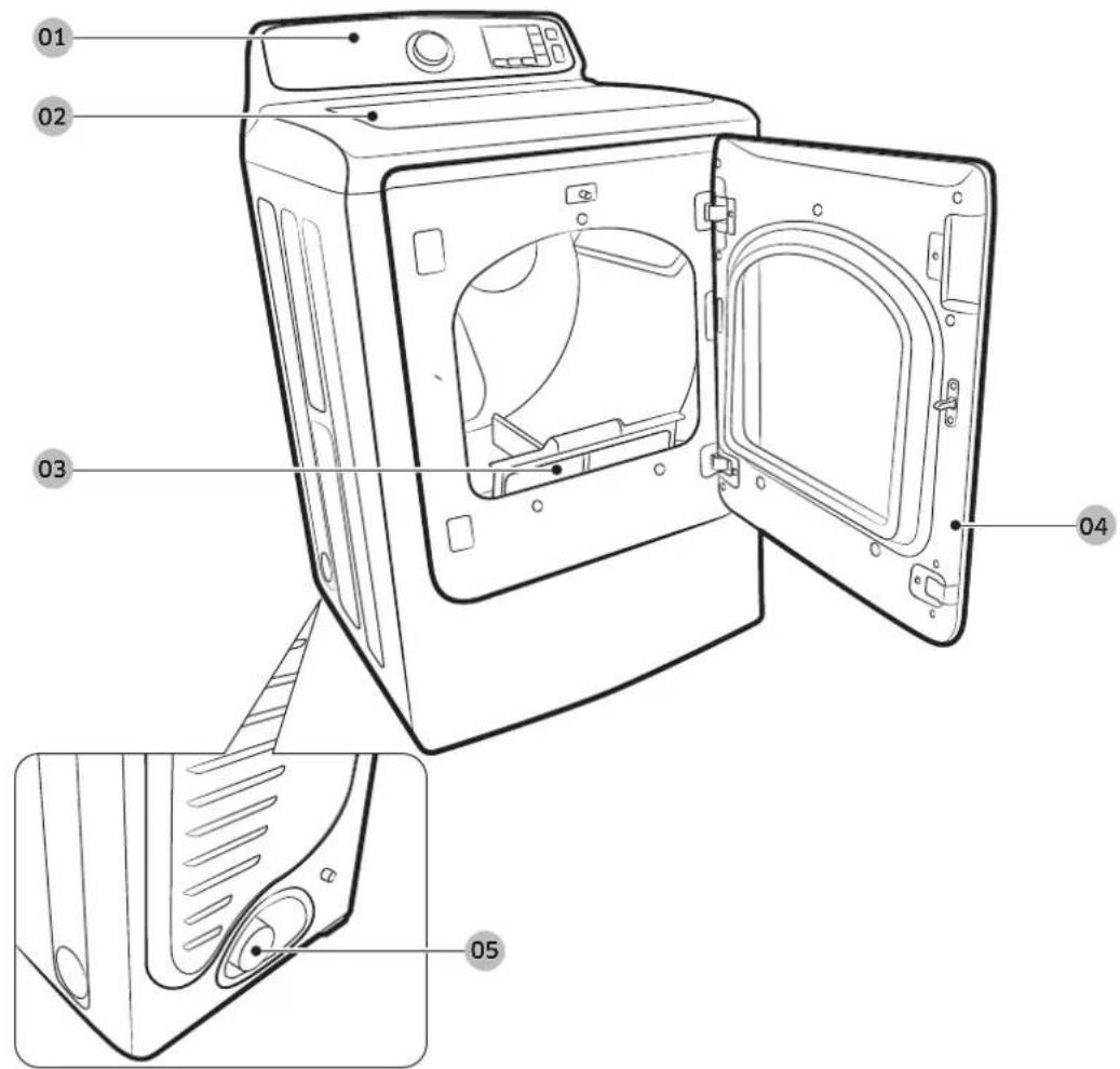
01 Control panel
02 Work top
03 Filter
04 Door
05 Duct exhaust
10 English

WARNING
Packing materials can be dangerous to children. Keep all packing material (plastic bags, polystyrene, etc.) well out of children's reach.

CAUTION
- Do not move the product while holding the front part of the top cover of the dryer. This may cause the cover to separate from the dryer and result in injury.
- Wear protective gloves whenever lifting or carrying the dryer to prevent personal injury or strain.
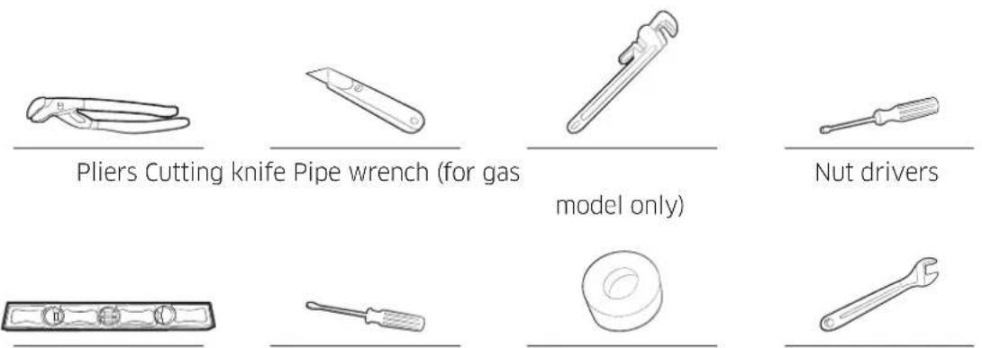
Leveller Phillips screwdriver Duct tape Wrench
Installation
Before installation
Please read the following instructions carefully before installing the dryer. These instructions should be kept for future reference.

WARNING
Remove the door from all discarded appliances to avoid the danger of a child suffocating.
Control board and inlet valve are intentionally not grounded and may present a risk of electric shock only during servicing.
Service personnel - Do not contact this part while appliance is energized.
Basic requirements
Make sure you have everything necessary for proper installation
• A GROUNDED ELECTRICAL OUTLET is required. See Electrical Requirements.
• A POWER CORD for electric dryers (except in Canada).
• GAS LINES (if installing a gas dryer). The gas lines must meet national and local codes.
- EXHAUST SYSTEM - must be rigid metal or flexible stiff-walled metal exhaust ducting.
Location considerations
Locate the dryer where there is enough space at the front for loading the dryer, and enough space behind for the exhaust system. This dryer is factory-ready for rear exhaust. To exhaust out the bottom or the right or the left (electric model only), use the accessory exhaust kit (sold separately). Instructions are included with the kit. It's important to make sure the room has enough fresh air. The dryer must be located where there is no air-flow obstruction.
On gas dryers, adequate clearance as noted on the data plate must be maintained to ensure adequate air for combustion and proper dryer operation.
Do not install or store the dryer in an area where it will be exposed to water and/or weather. Keep the dryer area clear of combustible materials, gasoline, and other flammable vapors and liquids. A dryer produces combustible lint. The area around the dryer should be kept lint free.
Alcove or closet installation
Minimum clearances between the dryer and adjacent walls or other surfaces are: 2" in front, 17" on top, 1" on either side, and 5" in the back.
The closet front must have two unobstructed air openings for a combined minimum total area of 72 in ^2 with 3" minimum clearance on the top and bottom. A louvered door with equivalent space clearance is acceptable.

WARNING
- You must exhaust the dryer to the outside to reduce the risk of fire when you install the dryer in and alcove or closet.
- To reduce the risk of fire, you must exhaust the dryer to the outdoors. See "Exhausting" section.
- No other fuel-burning appliance should be installed in the same closet as the dryer.
Installation
Ducting requirements
| Weather hood type |
| Recommended Use only for short-run installation |
| 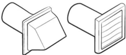 4" (10.2 cm) 4" (10.2 cm) | 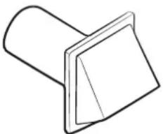 2.5" (6.4 cm) 2.5" (6.4 cm) |
| No. of 90°elbows | Rigid | Metallicflexible* | Rigid | Metallicflexible* |
| 0 80 ft. (2 | 4.4 m) 41 ft. (12.4 m) | 74 ft. (22.6 m) | 33 ft. (10.1 m) | |
| 1 68 ft. (2 | 0.7 m) 37 ft. (11.2 m) | 62 ft. (18.9 m) | 29 ft. (8.8 m) | |
| 2 57 ft. (1 | 7.4 m) 33 ft. (10.1 m) | 51 ft. (15.5 m) | 25 ft. (7.6 m) | |
| 3 47 ft. (1 | 4.3 m) 29 ft. (8.8 m) | 41 ft. (12.5 m) | 21 ft. (6.5 m) | |
 * Do not use non-metallic flexible duct. * Do not use non-metallic flexible duct. |
• Use a 4-inch (10.2 cm) diameter rigid aluminum or rigid galvanized steel duct.
• Do not use a smaller duct.
- Ducts larger than 4 inches (10.2 cm) in diameter can cause increased lint accumulation. Lint accumulation should be cleaned regularly.
- If a flexible metal duct must be used, use the type with a stiff sheet metal wall. Do not use a flexible duct with a thin foil wall. Serious blockage can result if the flexible metal duct is bent too sharply.
- Never install any type of flexible duct in walls, ceilings, or other concealed spaces.
- Keep the exhaust duct as straight and short as possible.
- Secure joints with duct tape. Do not use screws.
- Plastic flexible duct can kink, sag, be punctured, reduce airflow, extend drying times, and affect dryer operation.
- Exhaust systems longer than recommended can extend drying times, affect machine operation, and may collect lint.
- The exhaust duct should end with an exhaust hood with a swing-out damper to prevent back drafts and the entry of wildlife. Never use an exhaust hood with a magnetic damper.
14 English
- The hood should have at least 12 inches (30.5 cm) of clearance between the bottom of the hood and the ground or other obstruction. The hood opening should point down.
• Never install a screen over the exhaust outlet.
- To avoid lint buildup, do not exhaust the dryer directly into a window well. Do not exhaust under a house or porch.
- If exhaust ductwork must run through an unheated area, the duct should be insulated and slope slightly down towards the exhaust hood to reduce condensation and lint buildup.
- Inspect and clean the interior of the exhaust system at least once a year. Unplug the power cord before cleaning.
- Check frequently to be sure the exhaust hood damper opens and closes freely.
- Check once per month, and clean at least one time per year. Note: If clothes are not getting dry, then check ducting for obstructions.
- Do not exhaust dryer into any wall, ceiling, crawl space, or concealed space of a building, gas vent, or any other common duct or chimney. This could create a fire hazard from lint expelled by the dryer.
If the new dryer is being installed into an existing exhaust system, you must make sure:
• The exhaust system meets all local, state, and national codes.
• That a flexible plastic duct is not used.
• To Inspect and clean all lint buildup from inside the existing duct.
• The duct is not kinked or crushed.
• The exhaust hood damper opens and closes freely.
The static pressure in any exhaust system must not exceed 0.83 inches of water column, or be less than 0.
This can be measured with the dryer running with a manometer at the point where the exhaust duct connects to the dryer. A no-heat setting should be used. The dryer tumbler should be empty and the lint filter clean.
Installation
Exhausting
The dryer must not be exhausted into a chimney, a wall, a ceiling, an attic, a crawl space, or a concealed space of a building.
Exhausting the dryer to the outside will prevent large amount of lint and moisture from being blown into the room.
In the United States
• All dryers must be exhausted to the outside.
• The required exhaust duct is 4 inches (10.2 cm) in diameter.
- Use only those foil-type flexible ducts, if any, specifically identified for use with the appliance by the manufacturer and that comply with the Outline for Clothes Dryer Transition Duct. Use Subject 2158A.
- See "Ducting requirements" in the "Installation" section for the maximum duct length and number of bends that can be used.
- The total length of flexible metal duct must not exceed 7' 10½" (2.4 m).
- Do not assemble the duct with screws or other fasteners means that extend into the duct and catch lint
In Canada
• All dryer must be exhausted to the outside.
• The exhaust duct should be 4 inches (10.2 cm) in diameter.
- Use only those foil-type flexible ducts, if any, specifically identified for use with the appliance by the manufacturer shall be used.
- See "Ducting requirements" in the "Installation" section for the maximum duct length and number of bends.
- The total length of flexible metal duct shall not exceed 7' 10½" (2.4 m).
- Do not assemble the duct with screws or other fasteners means that extend into the duct and catch lint.
Outside the U.S. and Canada
• Refer to the local codes.
WARNING
You must exhaust the dryer to the outside to reduce the risk of fire when you install the dryer in an alcove or closet.
NEVER USE A PLASTIC OR NON-METAL FLEXIBLE DUCT.
If your existing ductwork is plastic, non-metal, or combustible, replace it with metal.
Use only a metal exhaust duct that is non-flammable to ensure containment of exhaust air, heat, and lint.
Gas requirements

WARNING
• Use only natural or LP (liquid propane) gases.
- THE INSTALLATION MUST CONFORM WITH LOCAL CODES, OR IN THE ABSENCE OF LOCAL CODES, WITH THE NATIONAL FUEL GAS CODE ANSI/Z223.1, LATEST REVISION (FOR THE UNITED STATES), OR WITH THE CAN /CGA-B149 INSTALLATION CODES (FOR CANADA).
- Gas dryers are equipped with a burner vent for use with natural gas. If you plan to use your dryer with LP (liquid propane) gas, it must be converted for safe and proper performance by a qualified service technician.
- A 1/2" (1.27 cm) gas supply line is recommended and must be reduced to connect to the 3/8" (1 cm) gas line on your dryer. The National Fuel Gas Code requires that an accessible, approved manual gas shut-off valve be installed within 6" of your dryer.
- Gas dryers installed in residential garages must be raised 18 inches (46 cm) above the floor.
Additionally, a 1/8" (0.3 cm) N.P.T. (National Pipe Thread) plugged tapping, accessible for test gauge connection, must be installed immediately upstream of your dryer's gas supply connection.
- Your dryer must be disconnected from the gas supply pipe system during any pressure testing of the system.
- DO NOT reuse old flexible metal gas lines. Flexible gas lines must be design certified by the American Gas Association (CGA in Canada).

NOTE
- Any pipe joint compound used must be resistant to the action of any liquefied petroleum gas.
• As a courtesy, most local gas utilities will inspect a gas appliance installation.

NOTE
GAS IGNITION: Your dryer uses an automatic ignition system to ignite the burner. There is no constant burning pilot.
Installation
Commonwealth of Massachusetts installation instructions
Your dryer must be installed by a licensed plumber or gas fitter. A "T" handle manual gas valve must be installed in the gas supply line to your dryer. If a flexible gas connector is used to install your dryer, the connector can be no longer than 3' (36").

WARNING
• Gas leaks may occur in your system, creating a dangerous situation.
• Gas leaks may not be detected by smell alone.
• Gas suppliers recommend you purchase and install a UL-approved gas detector.
- Install and use in accordance with the manufacturer's instructions.
Electrical requirements

NOTE
The wiring diagram is located on the plate below the control panel or frame back.

WARNING
- Improperly connecting the equipment grounding conductor can result in a risk of electric shock.
Check with a qualified electrician or serviceman if you are in doubt as to whether your dryer is properly grounded. Do not modify the plug provided with your dryer - if it doesn't fit the outlet, have a proper outlet installed by a qualified electrician.
- To prevent unnecessary risk of fire, electrical shock, or personal injury, all wiring and grounding must be done in accordance with local codes, or in the absence of local codes, with the National Electrical Code, ANSI/NFPA No. 70-Latest Revision (for the U.S.) or the Canadian Electrical Code CSA C22.1 - Latest Revisions and local codes and ordinances. It is your responsibility to provide adequate electrical services for your dryer.
- All gas installations must be done in accordance with the national Fuel Code ANSI/Z2231 – Latest Revision (for the U.S.) or CAN/CGA – B149 Installation Codes – Latest Revision (for Canada) and local codes and ordinances.
Grounding
This dryer must be grounded. In the event of malfunction or breakdown, the ground will reduce the risk of electrical shock by providing a path of least resistance for the electrical current.

WARNING
Improper connection of the equipment-grounding conductor can result in a risk of electric shock. Check with a qualified electrician or service representative or personnel if you are in doubt as to whether the appliance is properly grounded.
Gas models

WARNING
- Your dryer has a cord with an equipment-grounding conductor and a grounding plug. The plug must be plugged into an appropriate outlet that is properly installed and grounded in accordance with all local codes and ordinances.
- Do not modify the plug provided with your dryer – if it doesn't fit the outlet, have a proper outlet installed by a qualified electrician.
- Never connect the ground wire to plastic plumbing lines, gas lines, or hot water pipes.
Electric models

WARNING
- Your dryer has an optional cord with an equipment-grounding conductor and a grounding plug.
This cord is sold separately.
- The plug must be plugged into an appropriate outlet that is properly installed and grounded in accordance with all local codes and ordinances.
- Do not modify the plug provided with your dryer – if it doesn't fit the outlet, have a proper outlet installed by a qualified electrician.
- If a power cord is not used and the electric dryer is to be permanently wired, the dryer must be connected to a permanently grounded metal wiring system, or an equipment grounding conductor must be run with the circuit conductors and connected to the equipment grounding terminal or lead on the dryer.
Installation
Electrical connections
Before operating or testing, follow all grounding instructions in the "Grounding" section. An individual branch (or separate) circuit serving only your dryer is recommended. DO NOT USE AN EXTENSION CORD.
Gas models - U.S. and Canada
A 120 volt, 60 Hz AC approved electrical service, with a 15-ampere fuse or circuit breaker is required.
Electric models - U.S. only
Most U.S. dryers require a 120 / 240 volt, 60 Hz AC approved electrical service. Some require 120 / 208 volt, 60 Hz approved electrical service. The electric service requirements can be found on the data label located behind the door. A 30-ampere fuse or circuit breaker on both sides of the line is required.
• If a power cord is used, the cord should be plugged into a 30-ampere receptacle.
• The power cord is NOT provided with U.S. electric model dryers.

WARNING
Risk of Electric Shock
When local codes allow, the dryer electrical supply may be connected by means of a new power supply cord kit, marked for use with a dryer, that is U.L. listed and rated at a minimum of 120/240 volts, 30-ampere with three No. 10 copper wire conductors terminated with closed loop terminals, open-end spade lugs with turned up ends, or with tinned leads.
- Do not reuse a power supply cord from an old dryer. The power cord electric supply wiring must be supported at the dryer cabinet by a suitable UL-listed strain relief.
- Grounding through the neutral conductor is prohibited for (1) new branch-circuit installations, (2) mobile homes, (3) recreational vehicles, and (4) areas where local codes prohibit grounding through the neutral conductor. (Use a 4-prong plug for a 4 wire receptacle, NEMA type 14-30R.)
Electric models - Canada Only
- A 120 / 240 volt, 60 Hz AC approved electrical service fused through a 30-ampere fuse or circuit breaker on both sides of the line is required.
- All Canadian models are shipped with the power cord attached. The power cord should be plugged into a 30-ampere receptacle.

NOTE
It is not permissible to convert a dryer in Canada to 208 volts.
Step-by-step installation
For proper installation, we recommend that you hire a qualified installer.
Read these instructions completely before you begin the installation.
To install the dryer, follow these steps:
- Move your dryer to an appropriate location for installation. Consider installing the dryer and washer sideby-side so you have easy access to both appliances.
NOTE
To move the dryer easily, lay two of the carton cushion-tops on the floor. Tip your dryer on its side so it lies across both cushion-tops. Push the dryer so that it is near its final location. Set your dryer upright.
Leave enough room around the dryer so you can attach the duct work, power cord, etc.
-
If you need to change the direction of the door, go to "Door reversal" on page 32. When done, return to Step 3 below.
-
Review the "Exhausting" section before installing the exhaust system. Install the duct work from your dryer to the exhaust hood. The crimped end of the duct sections must point away from your dryer. DO NOT use sheet metal screws when assembling ducting. These joints should be taped. Never use plastic flexible exhaust material.
NOTE
A tip for tight installations: Attach a section of the exhaust system to your dryer before putting it in place. Use duct tape to secure this section to your dryer, but do not cover the ventilation slots at the back of the dryer cabinet.
-
If you have an electric model, skip to Step 6. If you have a gas model, go to the next step.
-
Review the "Gas requirements" section, then follow the lettered steps below.
A. Remove the pipe thread protective cap.
B. Apply pipe joint compound or about 1 1/2 wraps of Teflon tape over all threaded connections.
The pipe joint compound must be resistant to the action of any liquefied petroleum gas.
C. Connect the gas supply to your dryer. An additional fitting is required to connect the 3/4" (1.9 cm) female thread end of a flexible connector to the 3/8" (1 cm) male threaded end on the dryer.
D. Securely tighten the gas line fitting over the threads.
E. Turn on the gas supply. Check all gas connections for leaks using a soap solution. If bubbles appear, tighten the connections and recheck. DO NOT use an open flame to check for gas leaks.
F. Go to Step 6.
English 21
Installation
- Review the "Electrical requirements" section, then follow the 3 Wire system connection instructions (Step 7) or 4 Wire system instructions (Step 8) below.
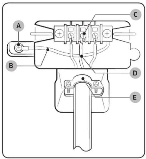
- Three Wire system instructions:
A. External ground connector
B. Neutral grounding wire (white)
C. Center silver-colored terminal block screw
D. Neutral wire (white or center wire)
E. 34 " (1.9 cm) UL-listed strain relief
a. Loosen or remove the center terminal block screw.
b. Connect the neutral wire (white or center wire) of the power cord to the center, silver-colored terminal screw of the terminal block. Tighten screw.
c. Connect the other wires to outer terminal block screws. Tighten screws.
d. Tighten the strain relief screws.
e. Insert the tab of the terminal block cover into your dryer's rear panel slot.
Secure the cover with a hold-down screw.
WARNING
If converting from a 4-wire electrical system to a 3-wire, you must connect the ground strap to the terminal block support to ground the dryer frame to the neutral conductor.
NOTE
We recommend using ring terminals. If you use strap terminals, please ensure you install them perfectly.
22 English
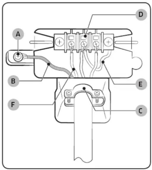
- Four Wire System instructions:
A. External ground connector
B. Green or bare copper wire of power cord
C. 34 " (1.9 cm) UL-listed strain relief
D. Center silver-colored terminal block screw
E. Neutral grounding wire (white)
F. Neutral wire (white or center wire)
a. Remove the External ground connector screw.
b. Connect the ground wire (green or unwrapped) of the power cord to the external ground connector screw. If you want to connect B (Green or bare copper wire of power cord) to the Neutral Post without connecting it to A (cabinet ground), call a service technician.
c. Loosen or remove the center terminal block screw.
d. Connect the neutral wire (white or center wire) of the power cord and the appliance ground wire (white) under the central screw of the terminal block.
e. Connect the other wires to the outer terminal block screws. Tighten screws.
f. Tighten the strain relief screws.
g. Insert the tab of the terminal block cover into your dryer's rear panel slot.
Secure the cover with a hold-down screw.

NOTE
We recommend using ring terminals. If you use strap terminals, please ensure you install them perfectly.
Installation

WARNING
For U.S. models: Risk of electrical shock
- All U.S.models are designed for a 3-WIRE SYSTEM CONNECTION. The dryer frame is grounded to the neutral conductor at the terminal block. A 4-WIRE SYSTEM CONNECTION is required for new or remodeled construction, mobile homes, or if local codes do not permit grounding through neutral. If you use the 4-wire system, you cannot ground the dryer frame to the neutral conductor at the terminal block.
- Remove the terminal block cover plate. Insert the power cord with a UL-listed strain relief through the hole provided in the cabinet near the terminal block.
- A strain relief must be used. Do not loosen the nuts already installed on the terminal block. Be sure they are tight. Use a 3/8" (1cm) deep well socket.
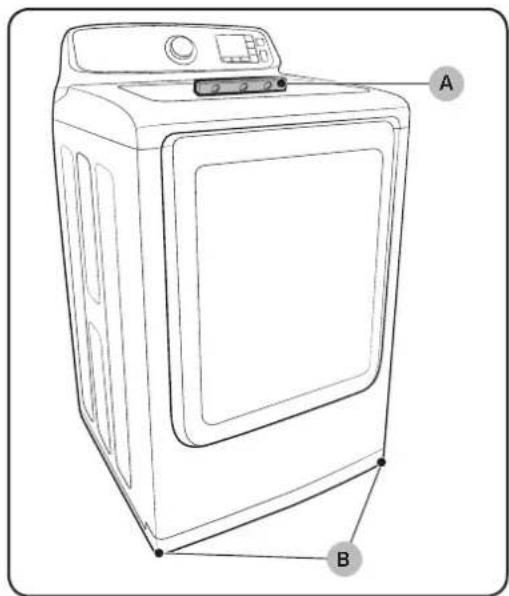
- To ensure that the dryer provides optimal drying performance, it must be level. To level the dryer, follow the lettered steps below:
A. Using a leveller (A), check if the dryer is level side to side and then front to back.
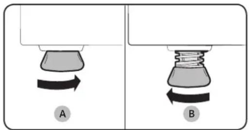
B. If the dryer is not level, adjust the leveling feet (B) on the bottom of the dryer until the dryer is level side to side and back to front.
Turning the feet clockwise retracts the feet. Turning the feet clockwise loosens and extends them.
natural_image
Two diagrams showing a mechanical component with rotational arrows, labeled A and B (no text or symbols beyond labels)
NOTE
If you have a dryer and dryer:
- To set the dryer to the same height as the washer, fully retract (A) the leveling feet by turning them counterclockwise, then loosen (B) the feet by turning them clockwise. Once the dryer is the same height as the washer, follow the directions above to level the dryer.
-
Adjust the leveling feet only as much as necessary to level the dryer. Extending the leveling feet more than necessary can cause the dryer to vibrate.
-
Make sure all gas connections (on gas models) and exhaust, and electrical connections are complete.
Plug in your dryer, and then check its operation by using the checklist on page 28.
- For GAS MODELS ONLY: The burner may not ignite initially due to air in the gas line. Allowing your dryer to operate on a heat setting will purge the line. If the gas does not ignite within 5 minutes, turn your dryer off and wait 5 minutes. Be sure the gas supply to your dryer has been turned on. To confirm gas ignition, check the exhaust for heat.
Installation
Connecting the inlet hose
natural_image
Illustration of a hand adjusting two valve fittings (no text or symbols present)
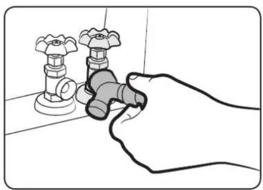
Method1
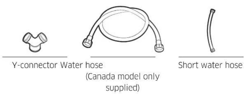
The dryer must be connected to the cold water faucet using the new inlet hoses. Do not use old hoses. (long hose : Canada model only supplied)
- If space permits, attach the brass female end of the "Y" connector to the cold water faucet.
- Turn the cold water faucet off.
- Attach the straight end of the long hose to the "Y" connector.
- Using pliers, tighten the coupling with an additional two-thirds turn.

NOTE
Do not overtighten, as it may damage the coupling.
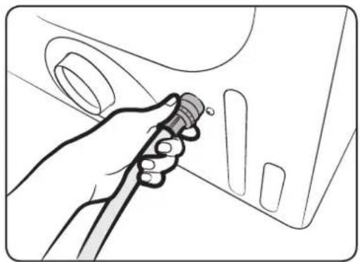
- Attach the angled end of the long hoses to the fill valve at the bottom of the dryer's rear frame. Screw on the coupling by hand until it is seated on the fill valve connector.
- Using pliers, tighten the coupling with an additional two-thirds turn.

NOTE
Do not overtighten, as it may damage the coupling.
-
Turn the cold water faucet on.
-
Check for leaks around the "Y" connector, faucets, and hoses.
natural_image
Illustration of a hand using a tool to adjust or install a car component (no text or symbols visible)
Method2
The dryer must be connected to the cold water faucet using the new inlet hoses. Do not use old hoses. (long hose : Canada model only supplied)
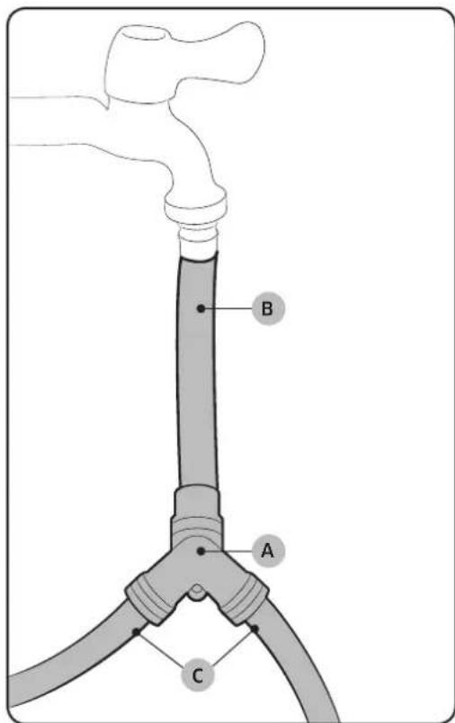
- If the "Y" connector (A) cannot be attached directly to the cold water faucet, the short hose must be used.
- Turn the cold water faucet off.
- Attach the short inlet hose (B) to the cold water faucet.
Screw on the coupling by hand until it is seated on the faucet.
- Using pliers, tighten the coupling with an additional two-thirds turn.
NOTE
Do not overtighten, as it may damage the coupling.
Installation
natural_image
Illustration of a hand using a tool to adjust or install a car door panel (no text or symbols visible)
- Attach the 'Y' connector to the brass male end of the small hose.
Screw on the coupling by hand until it is seated on the connector.
- Using pliers, tighten the coupling with an additional two-thirds turn.
NOTE
Do not overtighten, as it may damage the coupling.
-
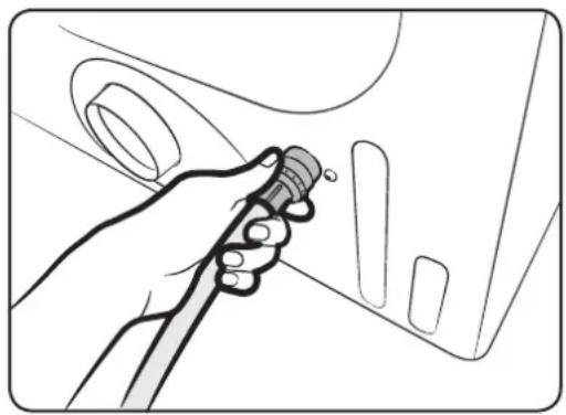
Attach the angled end of water hoses (C) to the fill valve at the bottom of the dryer rear frame. Screw on the coupling by hand until it is seated on the fill valve connector.
-
Using pliers, tighten the coupling with an additional two-thirds turn.
NOTE
Do not overtighten, as it may damage the coupling.
-
Turn the cold water faucet on.
-
Check for leaks around the "Y" connector, faucets and hoses.
Final installation check list
• The dryer is plugged into an electrical outlet and grounded properly.
• The exhaust ductwork is hooked up and the joints are taped.
• You have used rigid or stiff-walled flexible metal duct material, not plastic flexible duct.
• The dryer is level and is sitting firmly on the floor.
- For gas models: The gas is turned on and there are no gas leaks.
- Start your dryer to confirm that it runs, heats, and shuts off.
Vent blockage test (DV48J7700E(G)\*)
After the dryer is installed, start the Test to check if the exhaust system is applicable for the dryer. Vent Blockage Test detects duct state of the dryer automatically and report blockage state of the duct to the user. Proper duct state can help users to reduce drying time and save energy.

NOTE
Vent Blockage Test must run at cool state.
Operation method
- Check if the drum is empty and close the door.
(If there is any clothes or other item in the drum, correct diagnosis can't be made.)
- Press the power button to turn the dryer on, then press and hold both the Adjust time Up and Dry level buttons simultaneously for 3 seconds.
When entering the Test mode, "InS" will appear in the display.
(If other procedure is started before entering the Test mode, it's unable to enter the Test mode.)
- Starting diagnosis immediately after pressing the Start button,
During diagnosis, the operation state is displayed in the form of "000".
Diagnosis time is about 2 minutes. Don't open the door during diagnosis.
- About 2min. Later, if the diagnosis is completed, diagnosis result is displayed and tone is given.
If state of the exhaust system is normal, "End" appears and completion sounds is given. If the exhaust system can't exhaust smoothly, "CLg" appears and alarm sounds is given. In case of any other problem, information code appears; Check the information codes in this manual.
- In order to stop or cancel the diagnosis mode, press the power button to turn off your dryer.
- During diagnosis, if "C1" appears, check if the door is open.
- The result displays about 5 min. and is off automatically 5 min. later. You may close it directly by pressing the power button (off).

NOTE
- During or after diagnosis, the internal drum is hot; Be careful and don't be scalded. Vent Blockage Test is used to check if there is some problem to the current exhaust system when the dryer is set for the first time.
- If the diagnosis result displays “CLg” (the exhaust system is blocked), refer to “DUCTING REQUIREMENTS” and “DRYER EXHAUST TIPS” section of this manual and take proper measures for drying.
Installation
- If diagnosis is suspended, it could result in the wrong results. It must be tested according to diagnosis procedures.
- Even if the diagnosis result is normal ("End"), the exhaust system may also be interrupted or blocked slightly. Set properly according to Installation process of this manual.
Dryer exhaust tips
natural_image
Diagram of a mechanical device with a lever and directional arrow, no text or symbols present
WARNING
Plastic or non-metal flexible duct presents a potential fire hazard.
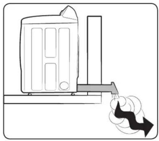
- Make sure your dryer is installed properly so it exhausts air easily.
natural_image
Diagram of a mechanical assembly with two cylindrical components connected by a belt, showing alignment and force direction (no text or symbols)
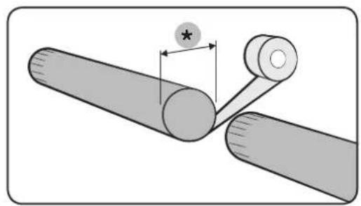
- Use 4"(*) diameter rigid metal duct. Tape all joints, including at the dryer.
Never use lint-trapping screws.
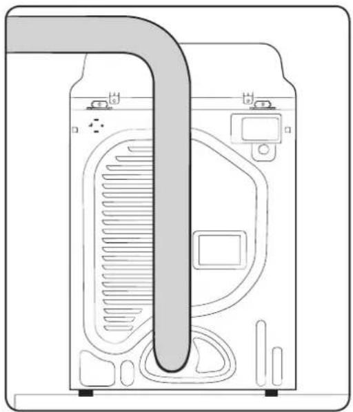
natural_image
Diagram of a refrigerator interior showing airflow path and seating area (no text or labels)
- Keep ducts as straight as possible.
natural_image
Simple diagram showing a pipe with a wavy arrow pointing downward, no text or symbols present
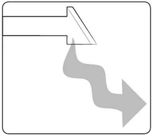
- Clean all old ducts before installing your new dryer.
Be sure the vent flap opens and closes freely.
Inspect and clean the exhaust system annually.
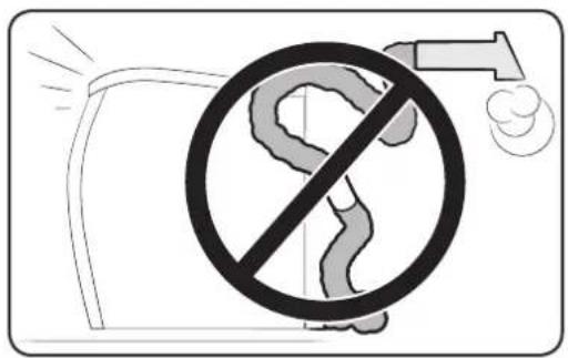
Don't let a poor exhaust system slow drying by:
- Restricting your dryer with a poor exhaust system.
Installation
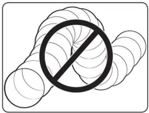
- Using a plastic, thin foil, or non-metal flexible duct.
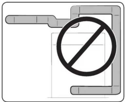
- Using unnecessarily long ducts that have many elbows.
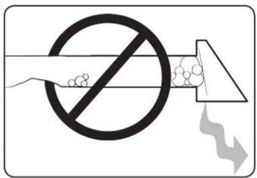
- Using crushed or clogged venting or ducts.
32 English
Door reversal
natural_image
Technical line drawing of a door panel with two circular insets showing internal components (no text or symbols)
flowchart
graph TD
    A["Start"] --> B{Circular Process}
    B --> C["Control Button"]
    B --> D["Arrow Right"]
    B --> E["Arrow Left"]
    B --> F["Arrow Up"]
    B --> G["Arrow Down"]
    B --> H["Arrow Left"]
    B --> I["Arrow Right"]
    B --> J["Arrow Down"]
    B --> K["Arrow Up"]
    style B fill:#f9f,stroke:#333,stroke-width:2px
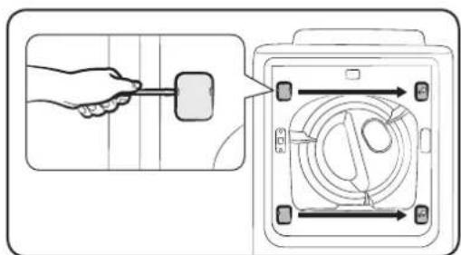
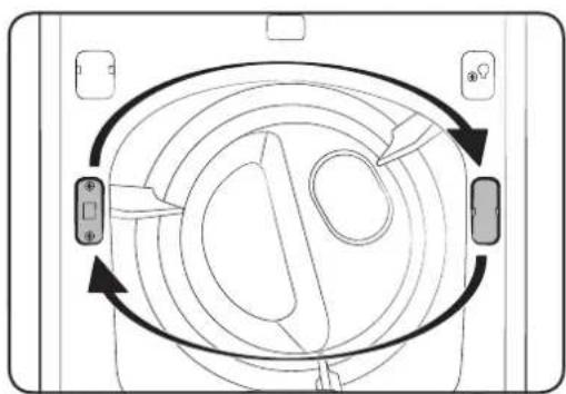
If you want to reverse the direction of the door, we recommend you call a qualified service technician.
- Unplug the power cord.
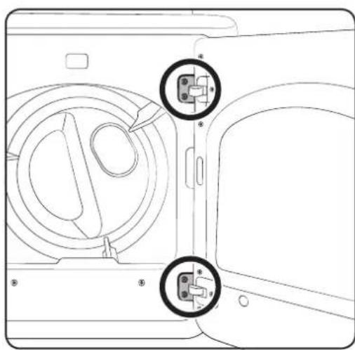
- Remove the four hinge screws from the door.
-
Remove the door by lifting it.
-
Remove the two screws from the holder-lever, and then remove the cover-holder.
- Assemble the holder-lever on the opposite side using the screws that were removed from the holder-lever-in Step 4.
-
Assemble the cover-holder on the opposite side.
-
Remove the two cover-hinges.
- Assemble the two cover-hinges on the opposite side.
NOTE
Use a flat head screwdriver(-) to remove the cover-holder's cover-hinge.
Installation
natural_image
Technical line drawing of a mechanical component with mounting holes and a curved central area, labeled B (no text or symbols beyond label)
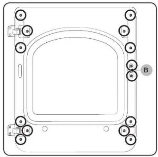
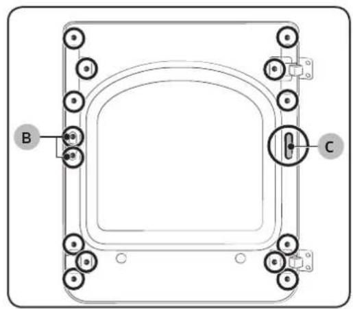
- Remove the 14 screws.

NOTE
Two screws (B) are longer than the other screws.
natural_image
Technical line drawing of a mechanical component with internal features and mounting holes (no text or symbols)
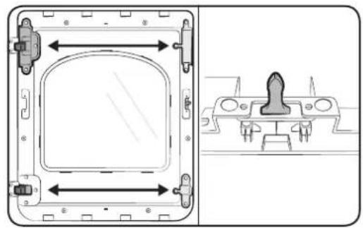
- Remove the holder-glass.
- Exchange the positions of:
A. The cover-hinge and handle door
B. The holder-hinge and guiderholder glass
- Remove the door-lever, and then install it on the opposite side.

NOTE
Refer to the illustrations on the left to aid you in the assembly process.
- Remove the cover-hole (C).
- Assemble the holder glass and then fasten the 14 screws that you removed in step 9.
- Attach the cover-hole.
natural_image
Pure technical diagram of a mechanical component with labeled points A, B, and C, showing no text or symbols beyond labels.
natural_image
Technical line drawing of a door panel with two circular components inserted, and a close-up of a key inserted into a lock (no text or symbols)
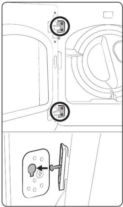
- Install the door on the frame-front and then fasten the 4 screws that you removed in step 2.
NOTE
Check the positions of the screws you installed in the hinge door.
Before you start
Guideline
Sorting and loading
- Place only one wash load in the dryer at a time.
- Avoid mixing heavy and lightweight items together.
• To increase drying efficiency when drying one or two items, add a dry towel to the load.
• For best results, untangle items before inserting into the dryer.
• Overloading restricts tumbling action and results in uneven drying and wrinkling.
• Unless recommended on the care label, avoid drying woolens or fiberglass items.
- Avoid drying unwashed items.
• Do not dry items soiled with oil, alcohol, gasoline, etc.
Cleaning the lint filter
natural_image
Diagram of a hand inserting a component into a device panel, showing no text or symbols
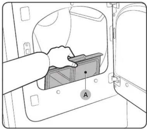
Clean the lint filter after or before every load. This is to prevent a fire hazard.
- Pull out the lint filter (A).
- Remove the lint.
- Slide the lint filter back into the place.
CAUTION
Do not operate the dryer without the lint filter in place. Do not use a damaged or broken filter case. This may cause degraded performance and/or fire.
Operations

WARNING
To reduce the risk of fire, electric shock, or injury to persons, read the IMPORTANT SAFETY INSTRUCTIONS before operating this appliance.
Control panel
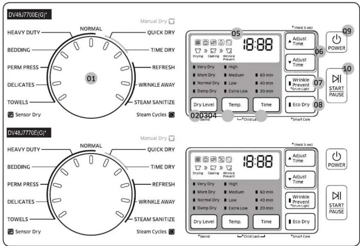
| 01 Cycle Selector | Turn the Cycle Selector to select the desired cycle. The indicator by the cycle name lights up. |
| 02 Dry Level | Press to adjust the dryness in the Sensor Dry and Steam Dry cycles except STEAM SANITIZE. An indicator light illuminates next to the desired dryness level.Press the button repeatedly to scroll through the Dry Level options. Larger or bulkier loads may require the Very Dry or More Dry for complete dryness.Damp Dry is designed to partially dry items. Use for items that lay flat or hang to dry. |
English 37
Operations
| 03 Temp. | Press to change the temperature for the current cycle.• High: For sturdy cottons or those labeled Tumble Dry.• Medium: For permanent press, synthetics, lightweight cottons, or items labeled Tumble Dry Medium.• Low: For heat sensitive items labeled Tumble Dry Low or Tumble Dry Warm.• Extra Low: Provides the lowest heated drying temperature possible. |
| 04 Time | Press to adjust the drying time, when using Manual Dry cycles. This button is not available for Sensor Dry cycles because exact drying times are determined by fluctuating humidity levels. |
| 05 Digital graphic display | Displays all cycle information, including cycle time, information code, and dryer status. | Filter Check Steam  | |
 | Child Lock Drying in progress  Drying Drying | |
 | Sound On/Off Cooling [7SYT]rogressCooling | |
 | Drum Light On/Off (DV48J7700E(G*) |  WrinklePrevent WrinklePrevent | Wrinkle Prevent inprogress |
 | Vent Sensor (DV48J7770E(G*) | | |
| 06 Adjust Time | Time can be added or subtracted from the automatically set times in the Manual Dry cycles (TIME DRY, QUICK DRY), and WRINKLE AWAY.To add or subtract time from the cycle, press the Adjust Time ▲ or ▼ until the desired time is displayed. |
| 07 Wrinkle Prevent | Wrinkle Prevent provides approximately 180 minutes of intermittent tumbling in unheated air at the end of the cycle to reduce wrinkling. Press Wrinkle Prevent to activate this feature.The indicator light above the pad will illuminate when Wrinkle Prevent is selected.The load is dry, and can be removed at any time during the Wrinkle Prevent cycle. |
| 08 Eco Dry | This function is available in the NORMAL and TIME DRY.When the Eco Dry function is activated, drying takes longer, but the power consumption is reduced.(When the Eco Dry function is enabled, the drying time can be extended up to 3 times depending on the specified temperature and the amount of laundry to be dried. When the product is shipped, the Eco Dry function is set to on by default.) |
| 09 Power | Press to turn on/off the dryer. |
| 10 Start/Pause | Press to start or stop an operation. |

NOTE
If you insert laundry into your dryer while it is extremely tangled immediately after your washer has finished a wash or spin cycle, it may degrade the drying efficiency or cause the door to open. We recommend that you disentangle your laundry before inserting it.
Operations
Simple steps to start
- Press Power to turn on the dryer.
- Turn the Cycle Selector to select a cycle.
- Change the cycle settings (Dry Level and Time) as necessary.
- The dryer provides the additional options: Wrinkle Prevent, and Eco Dry. Press to activate/deactivate the options.
- Press Start/Pause. The dryer indicator lights up, and the estimated cycle time appears on the display.
To change the cycle during operation
- Press Start/Pause to stop operation.
- Select a different cycle.
- Press Start/Pause again to start the new cycle.
Cycle overview
Sensor Dry cycles
Sensor Dry cycles automatically senses the moisture in the load and shuts the dryer off when the load reaches the dryness level you have selected with Dry Level.
| Cycle Description |
| NORMAL | For most fabrics including cotton, linens, and normally soiled garments.(If this cycle is selected, the Eco Dry function is enabled by default. For more information, refer to the description of the “Eco Dry” option.) |
| HEAVY DUTY | Use this cycle to get high heat for heavy fabrics such as jeans, corduroys, or work clothes. |
| BEDDING • For bulky | tems such as blankets, sheets, and comforters. |
| PERM PRESS | Dry wrinkle-free cottons, synthetic fabrics, knits, and permanent press fabrics automatically. |
| DELICATES • For heat | sensitive items at a low drying temperature. |
| TOWELS • For bath to | wels and similar items |
Operations
Manual Dry cycles
| Cycle Description |
| QUICK DRY • Provides | a 30 minute drying cycle. |
| TIME DRY | • Allows you to select a cycle time in minutes.(If this cycle is selected, the Eco Dry function is enabled by default. For more information, refer to the description of the “Eco Dry” option.) |
Steam Dry cycles
| Cycle Description | |
| REFRESH | Best for smoothing out wrinkles and reducing odors from loads consisting of one to four dry items. In this cycle a small amount of water is sprayed into the dryer drum after several minutes of tumbling with heat. Confirm that the laundry load is dry. |
| WRINKLE AWAY | Removes wrinkles from clothes stored in closets, etc.It provides wrinkle release via optimized steam care.For best results, load 2-3 items at once.You can extend the drying time by a minimum of 20 minutes, depending on the item type or load. Confirm that the laundry load is dry. |
| STEAM SANITIZE | Sanitizes garments by infusing high temperature heat deep into the fabric and injecting steam during the drying cycle.This cycle can make clothes soft and remove bad odors after drying. Confirm that the laundry load is wet or partially wet. |
Cycle guide
Always follow the care label when drying. If care label instructions are not available, use the following chart.
| Bedspreads & Comforters | Follow the care label instructions or dry using the BEDDING.Make sure the item is thoroughly dry before using or storing.May require repositioning to ensure even drying. |
| Blankets | Use the NORMAL and dry only one blanket at a time for best tumbling action.Make sure the item is thoroughly dry before using or storing. |
| Curtains & Draperies | Use the PERM PRESS and medium temperature to help minimize wrinkling.Dry these in small loads for best results and remove as soon as possible. |
| Cloth Diapers | Use the NORMAL and the Medium temperature settings for soft, fluffy diapers. |
| Down-filled Items (jackets, sleeping bags, comforters, etc.) | Use the NORMAL and medium temperature setting.Add a couple of dry towels to absorb moisture and shorten drying time. |
| Pillows | Use the NORMAL.Add a couple of dry towels and a pair of clean sneakers to help the tumbling action and to fluff the items.Do not dry kapok or foam pillows using a heated dryer cycle. |
| Plastics (shower curtains, outdoor furniture covers, etc.) | Use the TIME DRY and the Low or Extra Low temperature settings depending on the care label instructions. |

WARNING
Do not dry in the dryer: Fiberglass items (curtains, draperies, etc.).
- Woolens, unless recommended on the label.
- Items spotted or soaked with vegetable or cooking oils.
- Foam Rubber (rug backs, stuffed toys, shoulder pads, etc.)
Options
Operations
Child Lock
Child Lock prevents children from playing with the dryer.
When Child Lock is activated, all buttons except for the Power button are disabled.
To activate/deactivate Child Lock, simultaneously press and hold Temp. and Time for 3 seconds.

NOTE
If Child Lock is activated, and the dryer is turned off and then on again, Child Lock remains activated.
Drum Light
Lights the dryer drum while the dryer is running.
Press and hold Wrinkle Prevent for 3 seconds or longer.

NOTE
You can turn the drum light on and off while your dryer is running and when it is stopped.
If you do not turn the drum light off 5 minutes after turning it on, the drum light automatically turns off.
Sound
The Sound Off function can be selected during all cycles.
Press and hold Dry Level for 3 seconds or longer.

NOTE
When this function is selected, sound is turned off for all cycles.
Even if the power is turned off and on repeatedly, the setting is retained.
Smart Care
Smart Care lets you check the status of your dryer using a smart phone if it displays an information code. To use Smart Care you need:
• The Samsung Smart Care app
- A smart phone

NOTE
The Smart Care function has been optimized for : Galaxy & iPhone series (cannot be supported for some models).
Download the Samsung Smart Care app into your smart phone from the Android market or Apple App store. (Search word: "Samsung Smart Washer/Dryer")
To use Smart Care, follow these steps:
-
Press Power to turn the dryer on and then press and hold Eco Dry for 3 seconds. If you press a button other than Eco Dry after turning the dryer on, you will not be able to activate the Smart Care function.
-
When the Smart Care function is activated, the Smart Care indicator lights up on the display.
-
Run the Smart Care app on your smart phone.
-
Focus the smart phone's camera on the display panel of the dryer.
-
When the smart phone's camera is focused on the display panel of the dryer, the panel and information code is automatically recognized and the code type and countermeasures are displayed on the smart phone.
-
If the smart phone fails to recognize the information code more than twice, enter the information code displayed on the display panel of the dryer manually into the Smart Care app.
NOTE
Precautions when using Smart Care
- If light from a light bulb, fluorescent bulb, or lamp is reflected on the display panel of the dryer, the smart phone may not be able to recognize the panel or information code easily.
- If you hold the smart phone at too large an angle relative to the front of the display panel, it may not be able to recognize the information code. For best results, hold the smart phone so that the front of the panel and the smart phone are parallel or nearly parallel.
- The information code history is deleted after you use this function.
Maintenance
Keep the dryer clean to prevent deteriorated performance and to preserve its life cycle.
Vent Sensor (DV48J7770E(G) ^* )
Your Samsung dryer is equipped with a Vent Sensor, which detects and notifies you when it is time to clean the ductwork. Keep your dryer safe and efficient by cleaning the ducts when prompted.
See the table below for an explanation of indicator codes.
| Level | indicator | Status Solution | |
| 0 Off | | The ductwork is free from blockages. | - |
| 1 Lights up | | When a part of the duct or the lint filter is blocked by lint or a foreign object.When the resistance is high because the duct is too long or bent. | Check the duct connection and shorten the duct and straighten it if necessary.Check the lint filter or the duct and clean it if necessary. |
| 2 Blinks | | When the duct is blocked by lint or a foreign object.When the resistance is very high because the duct is too long or bent excessively. | Check the duct connection and shorten the duct and straighten it if necessary.Check the lint filter or the duct and clean it as soon as possible. |
In the LEVEL 2 state, the ℚ indicator blinks for 3 hours after the completion of the cycle. (If the Wrinkle Prevention function is activated, this message is displayed for up to 3 hours.) If the Power button is pressed or the door is opened, the power is immediately turned off.
NOTE
- For more information about the duct installation, please refer to the "Ducting requirements" section on page 14.
- Although the dryer is available even if the blockage message is displayed, the drying time may be extended.
- If the LEVEL 1 message is displayed the first time the dryer is run after installation, check the lint filter and the connection between the duct and the dryer, and clean the duct. If the LEVEL 1 message appears even after you have checked and cleaned the ducts, this may indicate that there are some restrictions of the duct due to the length, condition, etc. If this occurs, you can use the dryer normally and no countermeasures need to be taken. However, the drying time may be extended or the drying performance may be degraded.
46 English
Maintenance

WARNING
Control board and inlet valve are intentionally not grounded and may present a risk of electric shock only during servicing.
Service personnel - Do not contact this part while appliance is energized.
Cleaning
Control Panel
Clean with a soft, damp cloth. Do not use abrasive substances.
Do not spray cleaners directly on the panel. The control panel finish may be damaged by some laundry pre-treatment soil and stain remover products.
Apply such products away from your dryer and wipe up any spills or overspray immediately.
Tumbler
Remove any stains from the tumbler caused by crayon, ink, fabric dye (from new items such as towels or jeans) and so on with an all-purpose cleaner.
Tumble old towels or rags to remove any remaining stain or cleaning substance.
Once these steps are followed, stains may still be visible, but should not transfer to subsequent loads.
Powder coat tumbler
To clean the powder coat tumbler, use a damp cloth with a mild, non-abrasive cleaner suitable for easily marred surfaces.
Remove cleaner residue and dry with a clean cloth.
Dryer Exterior
Clean with a soft, damp cloth. Do not use abrasive substances.
Protect the surface from sharp objects.
Do not place any heavy or sharp objects or a detergent box on the dryer. They can scratch or damage the top cover of the dryer. Keep these items in a separately purchased pedestal or in a separate storage box.
The entire dryer has a high-gloss finish.
Avoid scratching or damaging the surface when using the dryer.
Dryer Exhaust System
Inspect and clean the dryer exhaust system yearly to maintain optimum performance.
The outside exhaust hood should be cleaned more frequently to ensure proper operation.
MaintenanceTroubleshooting
Checkpoints
If you encounter a problem with the dryer, first check the table below and try the suggestions.
| Problem Action | |
| Does not run. | Make sure the door is latched shut.Make sure the power cord is plugged into a live electrical outlet.Check the home's circuit breaker and fuses.Press or tap Start/Pause again if the door is opened during a cycle.Clean the lint filter. |
| Does not heat. | Check the home's circuit breaker and fuses.Some cycles do not require heating. Check the selected cycle again.For a gas dryer, make sure the gas supply is on.Clean the lint filter and exhaust duct.Check the lint filter and clean them if necessary.The dryer may have moved into the cool-down phase of the cycle. |
| Does not dry. | Check all of the above, plus...Make sure the exhaust hood outside the home can open and close freely.Check the exhaust system for lint buildup. Ducting should be inspected and cleaned annually.Use a 4" rigid metal exhaust duct.Do not overload. 1 wash load = 1 dryer load.Sort heavy items from lightweight items.Large, bulky items, such as blankets or comforters, may require repositioning to ensure even drying.Make sure that the dryer is draining properly to extract adequate water from the load.The load may be too small to tumble properly. Add a few towels and restart the dryer.The load may be too large to tumble properly. Remove some items and restart the dryer.Clean the lint filter. |
| Is noisy. | Check the load for objects such as coins, loose buttons, nails, etc. Remove promptly.It is normal to hear the dryer gas valve or heating element cycle on and off during the drying cycle.Make sure the dryer is levelled properly as outlined in the installation instructions.It is normal for the dryer to hum due to the high velocity of air moving through the dryer drum, fan, or exhaust system. |
| Dries unevenly. | Seams, pockets, and other similarly heavy areas may not be completely dry when the rest of the load has reached the selected dryness level. This is normal. You can choose a higher dryness level or a cycle that involves such a high dryness level.If one heavy item is dried with a light weighing load, such as one towel with sheets, it is possible that the heavy item will not be completely dry when the rest of the load has reached the selected dryness level.For best drying results, sort heavy items from lightweight items. |
| Has odours. | Household odours from paint, varnish, strong cleaners, etc. may enter the dryer with the surrounding room air. This is normal as the dryer draws the air from the room, heats it, pulls it through the tumbler, and exhausts it outside.When these odours linger in the air, completely ventilate the room before using the dryer.Use a cycle featuring the Refresh function. If odours persist, wash and dry the item again. |
| Lint on clothes. | Make sure the case filter is cleaned before every load. For clothes that naturally build up lint, clean the filter case during the cycle.Some fabrics are lint producers (for example, a fuzzy white cotton towel) and they must be dried separately from clothes that are lint trappers (for example, a pair of black linen pants).Divide larger loads into smaller loads for drying.Check pockets thoroughly before drying, then dry clothes.Remove lint inside the drum before drying. |
Maintenance
| Problem Action | |
| Items still wrinkled after Wrinkle Prevent (Wrinkle-Care, Wrinkle Release). | Small loads of 1 to 4 items work best.Load fewer items. Load similar-type items.Take out the items immediately after drying is complete. |
| Water drips from the nozzle when SteamCare starts. | This is steam condensation. The dripping water will stop after a short time. |
| Sprayed water is not visible during SteamCare. | Sprayed water is difficult to see when the door is closed. |
| Extended time. | Sensor Dry automatically senses the moisture in the load and shuts the dryer off when the selected dryness level is reached.The drying time can change according to the type and amount of laundry. See the cycle chart for reference. |
If a problem persists, contact a local Samsung service center.
If the dryer fails to operate, you may see an information code on the screen. Check the table below and try the suggestions.
| No Code Action | |
| 1 dC | | Operating the dryer with the door open.Make sure the door is properly closed.Make sure laundry is not caught in the door. |
| 2 FC | | Invalid power source frequencyCheck if you are using regular power source frequencies.Check the power frequency sensor circuit.Try restarting the cycle.If the information code remains, contact a customer service centre. |
| 3 AC | | Electronic control problem (Invalid Communication).First check the PCB and wire harness.If the information code remains, contact a customer service centre. |
| 4 3C | | Malfunction is detected in the motor relay circuit.Check the motor connection cable.Check the motor relay operation of the PCB.Check the drum belt. |
| 5 bC2 | | Incorrect button state.If the display PCB key circuit is shorted or not. |
| 6 HC | | High temperature heating checkClean the filter case or condenser.If the information code remains, contact a customer service centre.(enter the line test mode). |
| 7 HC4 | |
| 8 9C1 | | The electronic control needs to be checked (Over Voltage Error).Check the PCB and wire harness.Check if power is supplied properly.If the information code remains, contact a customer service centre. |
| 9 tC | | The Thermistor1 resistance is very low or high.Check for a clogged lint screenCheck if the vent system is restricted or .Check Thermistor1 resistance. |
| 10 tC5 | | The Thermistor2 resistance is very low or high.Check for a clogged lint screen.Check if the vent system is restricted.Check Thermistor2 resistance. |
Maintenance
If any information code keeps appearing on the screen, contact a local Samsung service center.
52 English
Specifications
Protecting the environment
This appliance is manufactured from recyclable materials. If you decide to dispose of this appliance, please observe local waste disposal regulations. Cut off the power cord so that the appliance cannot be connected to a power source. Remove the door so that animals and small children cannot get trapped inside the appliance.
Specifications
Specification sheet
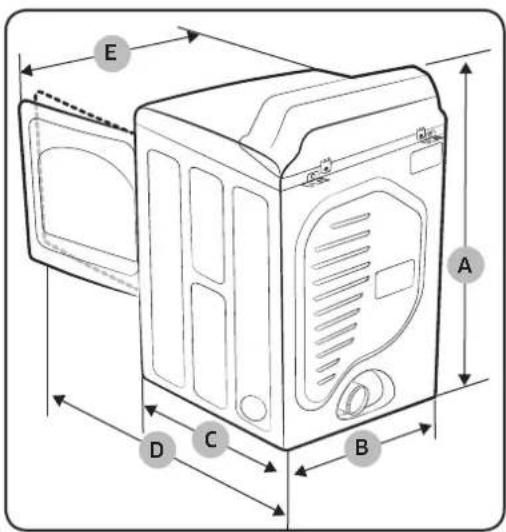
NOTE
"A. Height" Spec range through the leveling feet adjustment: 111.8 \~ 112.3 cm.
| Type Front loading dryer | |
| Model name | DV48J7700G*DV48J7770G* | DV48J7700E*DV48J7770E* |
| Dimensions(inches (cm)) | A. Height | Product 44.2 | (112.3) |
| Install 46.2 | |
| B. Width | Product 27.0 | (68.6) |
| Install 29.0 | |
| C. Depth | Product 30.0 | (76.3) |
| Install 35.0 | |
| D. Depth withdoor open 90° | Product 49.80 | (126.5) |
| Install 54.82 | |
| E. Width withdoor open 130° | Product 46.47 | (118.0) |
| Install 51,47 | |
| Water pressure (psi (kPa)) 20 ~ 116 (137 ~ 800) |
| NET weight (lb (kg)) 126 (57) 123 (56) | | |
54 English
| Type Front loading dryer | |
| Heater rating | Electric (W) 5300 | |
| Gas (BTU/hr) 22000 | |
English 55
Specifications
Cycle chart

NOTE
For best results, follow the load size recommendations for each dry cycle.
- Large load: Fill the drum to about 14 full. Do not add items over this level as they need to tumble freely.
• Medium load : Fill the drum to about 12 full.
- Small load: Fill the drum with 3\~5 items, not more than 14 full.
| Cycle Recommended items | | Load size | Dry Level |
| Sensor Dry | NORMAL | Cottons, work clothes, linen, mixed loads |  | Normal Dry (Adjustable) |
| HEAVY DUTY | Heavy Fabrics such as jean, corduroys, heavy work clothes |  | Normal Dry (Adjustable) |
| BEDDING | Bulky items such as blankets, sheets, comforters, pillows |  | Normal Dry (Adjustable) |
| PERM PRESS | Shirts, synthetic fabrics, knits, wrinkle-free cottons, permanent |  | Normal Dry (Adjustable) |
| DELICATES Underwear, blouses, lingerie |  | Normal Dry (Adjustable) |
| TOWELS Bath towels and similar items |  | Normal Dry (Adjustable) |
| Manual Dry | QUICK DRY Small loads |  | - |
| TIME DRY Any load |  | - |
| Steam Dry | REFRESH Shirts, trouser, comforter, pillows |  | - |
| WRINKLE AWAY Shirts, trousers, blouses |  | - |
| STEAM SANITIZE | Bedding, curtains, children's clothing |  | Very Dry (No change) |

NOTE
• ●: factory setting, ●: can be selected
| Cycle | Temperature setting | Time setting |
| High Medium Low Extra Low | |
| Sensor Dry | NORMAL | | ● | | | |
| HEAVY DUTY | ● | | | | |
| BEDDING | ● | | | | |
| PERM PRESS | | ● | | | |
| DELICATES | | | | ● | |
| TOWELS | ● | | | | |
| Manual Dry | QUICK DRY | ● ● | | | | |
| TIME DRY | ● ● | ● ● ● | | | |
| Steam Dry | REFRESH | ● | | | | |
| WRINKLE AWAY | ● ● | | | | |
| STEAM SANITIZE | ● | | | | |
| Cycle | Options |
| Wrinkle Prevent Ad | Just Time Eco Dry | |
| Sensor Dry | NORMAL | ● ● | | |
| HEAVY DUTY | ● | | |
| BEDDING | ● | | |
| PERM PRESS | ● | | |
| DELICATES | ● | | |
| TOWELS | ● | | |
| Manual Dry | QUICK DRY | ● | ● | |
| TIME DRY | ● ● ● | | |
| Steam Dry | REFRESH | ● | | |
| WRINKLE AWAY | ● | ● | |
| STEAM SANITIZE | ● | | |
English 57
Warranty (U.S.A)
SAMSUNG DRYER
LIMITED WARRANTY TO ORIGINAL PURCHASER
This SAMSUNG brand product, as supplied and distributed by SAMSUNG ELECTRONICS AMERICA, INC. (SAMSUNG) and delivered new, in the original carton to the original consumer purchaser, is warranted by SAMSUNG against manufacturing defects in materials and workmanship for a limited warranty period of:
• One (1) Year All Parts and Labor
• Two (2) Years Control Board Parts (Part Only)
This limited warranty begins on the original date of purchase, and is valid only on products purchased and used in the United States.
To receive warranty service, the purchaser must contact SAMSUNG for problem determination and service procedures.
Warranty service can only be performed by a SAMSUNG authorized service center.
The original dated bill of sale must be presented upon request as proof of purchase to SAMSUNG or SAMSUNG's authorized service center.
SAMSUNG will provide in-home service during the warranty period at no charge, subject to availability within the contiguous United States.
In-home service is not available in all areas.
To receive in-home service, product must be unobstructed and accessible to the service agent.
If service is not available, SAMSUNG may elect to provide transportation of the product to and from an authorized service center.
SAMSUNG will repair, replace, or refund this product at our option and at no charge as stipulated herein, with new or reconditioned parts or products if found to be defective during the limited warranty period specified above.
All replaced parts and products become the property of SAMSUNG and must be returned to SAMSUNG.
Replacement parts and products assume the remaining original warranty, or ninety (90) days, whichever is longer.
Warranty (U.S.A)
This limited warranty covers manufacturing defects in materials and workmanship encountered in normal, noncommercial use of this product and shall not apply to the following: damage that occurs in shipment; delivery and installation; applications and uses for which this product was not intended; altered product or serial numbers; cosmetic damage or exterior finish; accidents, abuse, neglect, fire, water, lightning, or other acts of nature or God; use of products, equipment, systems, utilities, services, parts, supplies, accessories, applications, installations, repairs, external wiring or connectors not supplied or authorized by SAMSUNG that damage this product or result in service problems; incorrect electrical line voltage, fluctuations and surges; customer adjustments and failure to follow operating instructions, maintenance and environmental instructions that are covered and prescribed in the instruction book; product removal and reinstallation; problems caused by pest infestations.
This limited warranty does not cover problems resulting from incorrect electric current, voltage or supply, light bulbs, house fuses, house wiring, cost of a service call for instructions, or fixing installation errors.
SAMSUNG does not warrant uninterrupted or error-free operation of the product.
EXCEPT AS SET FORTH HEREIN, THERE ARE NO WARRANTIES ON THIS PRODUCT EITHER EXPRESS OR IMPLIED, AND SAMSUNG DISCLAIMS ALL WARRANTIES INCLUDING, BUT NOT LIMITED TO, ANY IMPLIED WARRANTIES OF MERCHANTABILITY, INFRINGEMENT OR FITNESS FOR A PARTICULAR PURPOSE.
NO WARRANTY OR GUARANTEE GIVEN BY ANY PERSON, FIRM, OR CORPORATION WITH RESPECT TO THIS PRODUCT SHALL BE BINDING ON SAMSUNG.
SAMSUNG SHALL NOT BE LIABLE FOR LOSS OF REVENUE OR PROFITS, FAILURE TO REALIZE SAVINGS OR OTHER BENEFITS, OR ANY OTHER SPECIAL, INCIDENTAL OR CONSEQUENTIAL DAMAGES CAUSED BY THE USE, MISUSE, OR INABILITY TO USE THIS PRODUCT, REGARDLESS OF THE LEGAL THEORY ON WHICH THE CLAIM IS BASED, AND EVEN IF SAMSUNG HAS BEEN ADVISED OF THE POSSIBILITY OF SUCH DAMAGES.
NOR SHALL RECOVERY OF ANY KIND AGAINST SAMSUNG BE GREATER IN AMOUNT THAN THE PURCHASE PRICE OF THE PRODUCT SOLD BY SAMSUNG AND CAUSING THE ALLEGED DAMAGE.
WITHOUT LIMITING THE FOREGOING, PURCHASER ASSUMES ALL RISK AND LIABILITY FOR LOSS, DAMAGE, OR INJURY TO PURCHASER AND PURCHASER'S PROPERTY AND TO OTHERS AND THEIR PROPERTY ARISING OUT OF THE USE, MISUSE, OR INABILITY TO USE THIS PRODUCT.
THIS LIMITED WARRANTY SHALL NOT EXTEND TO ANYONE OTHER THAN THE ORIGINAL PURCHASER OF THIS PRODUCT, IS NONTRANSFERABLE AND STATES YOUR EXCLUSIVE REMEDY.
English 59
Some states do not allow limitations on how long an implied warranty lasts, or the exclusion or limitation of incidental or consequential damages, so the above limitations or exclusions may not apply to you. This warranty gives you specific rights, and you may also have other rights, which vary from state to state.
To obtain warranty service, please contact SAMSUNG at:
Samsung Electronics America, Inc.
85 Challenger Road
Ridgefield Park, NJ 07660
Visits by a Service Engineer to explain functions, maintenance or installation is not covered by warranty.
Please contact your Samsung call agent for help with any of these issues.
Warranty (CANADA)
SAMSUNG DRYER
LIMITED WARRANTY TO ORIGINAL PURCHASER
This SAMSUNG brand product, as supplied and distributed by SAMSUNG ELECTRONICS
CANADA, INC. (SAMSUNG) and delivered new, in the original carton to the original consumer purchaser, is warranted by SAMSUNG against manufacturing defects in materials and workmanship for a limited warranty period of:
• One (1) year part and labor
This limited warranty begins on the original date of purchase, and is valid only on products purchased and used in the Canada.
To receive warranty service, the purchaser must contact SAMSUNG for problem determination and service procedures.
Warranty service can only be performed by a SAMSUNG authorized service center.
The original dated bill of sale must be presented upon request as proof of purchase to SAMSUNG or SAMSUNG's authorized service center.
SAMSUNG will provide in-home service during the warranty period at no charge, subject to availability within the Canada.
In-home service is not available in all areas.
To receive in-home service, product must be unobstructed and accessible to the service agent.
If service is not available, SAMSUNG may elect to provide transportation of the product to and from an authorized service center.
SAMSUNG will repair, replace, or refund this product at our option and at no charge as stipulated herein, with new or reconditioned parts or products if found to be defective during the limited warranty period specified above.
All replaced parts and products become the property of SAMSUNG and must be returned to SAMSUNG.
Replacement parts and products assume the remaining original warranty, or ninety (90) days, whichever is longer.
This limited warranty covers manufacturing defects in materials and workmanship encountered in normal, noncommercial use of this product and shall not apply to the following: damage that occurs in shipment; delivery and installation; applications and uses for which this product was not intended; altered product or serial numbers; cosmetic damage or exterior finish; accidents, abuse, neglect, fire, water, lightning, or other acts of nature or God; use of products, equipment, systems, utilities, services, parts, supplies, accessories, applications, installations, repairs, external wiring or connectors not supplied or authorized by SAMSUNG that damage this product or result in service problems; incorrect electrical line voltage, fluctuations and surges; customer adjustments and failure to follow operating instructions, maintenance and environmental instructions that are covered and prescribed in the instruction book; product removal and reinstallation; problems caused by pest infestations.
This limited warranty does not cover problems resulting from incorrect electric current, voltage or supply, light bulbs, house fuses, house wiring, cost of a service call for instructions, or fixing installation errors.
SAMSUNG does not warrant uninterrupted or error-free operation of the product.
EXCEPT AS SET FORTH HEREIN, THERE ARE NO WARRANTIES ON THIS PRODUCT EITHER EXPRESS OR IMPLIED, AND SAMSUNG DISCLAIMS ALL WARRANTIES INCLUDING, BUT NOT LIMITED TO, ANY IMPLIED WARRANTIES OF MERCHANTABILITY, INFRINGEMENT OR FITNESS FOR A PARTICULAR PURPOSE.
NO WARRANTY OR GUARANTEE GIVEN BY ANY PERSON, FIRM, OR CORPORATION WITH RESPECT TO THIS PRODUCT SHALL BE BINDING ON SAMSUNG.
SAMSUNG SHALL NOT BE LIABLE FOR LOSS OF REVENUE OR PROFITS, FAILURE TO REALIZE SAVINGS OR OTHER BENEFITS, OR ANY OTHER SPECIAL, INCIDENTAL OR CONSEQUENTIAL DAMAGES CAUSED BY THE USE, MISUSE, OR INABILITY TO USE THIS PRODUCT, REGARDLESS OF THE LEGAL THEORY ON WHICH THE CLAIM IS BASED, AND EVEN IF SAMSUNG HAS BEEN ADVISED OF THE POSSIBILITY OF SUCH DAMAGES.
NOR SHALL RECOVERY OF ANY KIND AGAINST SAMSUNG BE GREATER IN AMOUNT THAN THE PURCHASE PRICE OF THE PRODUCT SOLD BY SAMSUNG AND CAUSING THE ALLEGED DAMAGE.
WITHOUT LIMITING THE FOREGOING, PURCHASER ASSUMES ALL RISK AND LIABILITY FOR LOSS, DAMAGE, OR INJURY TO PURCHASER AND PURCHASER'S PROPERTY AND TO OTHERS AND THEIR PROPERTY ARISING OUT OF THE USE, MISUSE, OR INABILITY TO USE THIS PRODUCT.
THIS LIMITED WARRANTY SHALL NOT EXTEND TO ANYONE OTHER THAN THE ORIGINAL PURCHASER OF THIS PRODUCT, IS NONTRANSFERABLE AND STATES YOUR EXCLUSIVE REMEDY.
62 English
Warranty (CANADA)
Some provinces do not allow limitations on how long an implied warranty lasts, or the exclusion or limitation of incidental or consequential damages, so the above limitations or exclusions may not apply to you.
This warranty gives you specific rights, and you may also have other rights, which vary from province to province.
To obtain warranty service, please contact SAMSUNG at:
Samsung Electronics Canada Inc.
2050 Derry Road West
Mississauga, Ontario L5N 0B9 Canada
www.samsung.com/ca/support (English)
www.samsung.com/ca_fr/support (French)
Visits by a Service Engineer to explain functions, maintenance or installation is not covered by warranty.
Please contact your Samsung call agent for help with any of these issues.
SAMSUNG

Scan the QR code* or visit www.samsung.com/spsn to view our helpful How-to Videos and Live Shows
*Requires reader to be installed on your smartphone
Scan this with your smartphone
QUESTIONS OR COMMENTS?
| COUNTRY CALL OR VISIT US ONLINE AT | |
| U.S.A 1-800-SAMSUNG (726-7864) www.samsung.com/us/support |
| CANADA 1-800-SAMSUNG (726-7864) | www.samsung.com/ca/support (English)www.samsung.com/ca_fr/support (French) |
| MEXICO 01-800-SAMSUNG (726-7864) www.samsung.com/mx/support |


DC68-03170Q-05_EN
Sèche-linge
natural_image
Two diagrams showing a mechanical component with rotational arrows, labeled A and B (no text or symbols beyond labels)
REMARQUE
natural_image
Illustration of a hand adjusting two valve fittings (no text or symbols present)
Méthode 1
natural_image
Illustration of a hand using a tool to adjust or install a car door panel (no text or symbols visible)
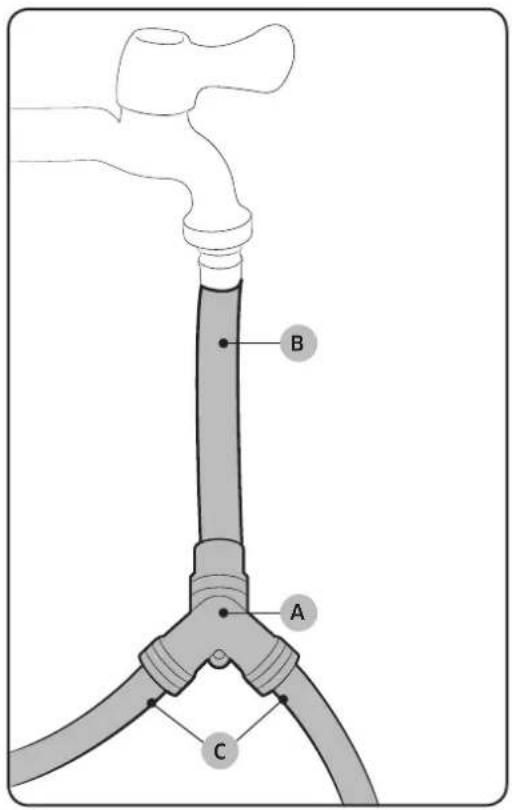
Méthode 2
natural_image
Illustration of a hand using a tool to adjust or install a car door panel (no text or symbols visible)
natural_image
Simple line drawing of a mechanical device with a downward arrow indicating motion or force (no text or symbols)
! AVERTISSEMENT
natural_image
Diagram of a mechanical assembly with two cylindrical components connected by a rod, showing alignment and dimension (no text or symbols)
natural_image
Diagram of a refrigerator interior showing ventilation duct and door (no text or labels)
natural_image
Simple diagram showing a pipe with a wavy arrow and a downward arrow, no text or symbols present.
natural_image
Technical line drawing of a door panel with two circular annotations highlighting internal components (no text or symbols present)
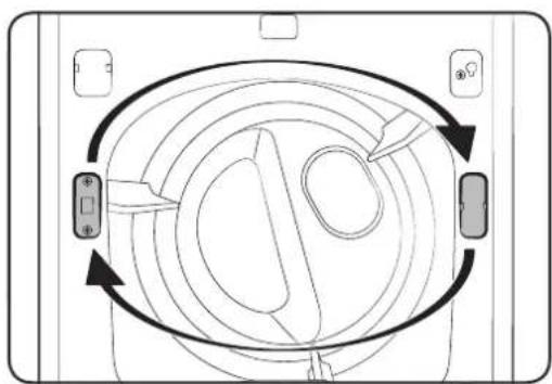
flowchart
graph TD
    A["Start"] --> B{Circular Flow}
    B --> C["Control Point 1"]
    B --> D["Control Point 2"]
    B --> E["Control Point 3"]
    B --> F["Control Point 4"]
    B --> G["End"]
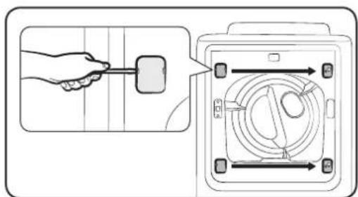
natural_image
Technical line drawing of a mechanical component with mounting holes and a central curved frame (no text or symbols)
- Retirez les 14 vis.

REMARQUE
natural_image
Technical line drawing of a mechanical component with internal features and mounting holes (no text or symbols)
natural_image
Pure technical diagram of a rectangular component with mounting holes and a central curved area, no text or symbols present.
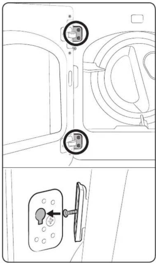
natural_image
Technical line drawing of a door panel with two circular components inserted, and a close-up of a key inserted into a lock (no text or symbols)
Ridgefield Park, NJ 07660
Samsung Electronics Canada Inc.
2050 Derry Road West
Mississauga, Ontario L5N 0B9 Canada
www.samsung.com/ca/support (English)
www.samsung.com/ca_fr/support (French)
natural_image
Simple line drawing of a coiled hose with flanged ends (no text or symbols)
natural_image
Two diagrams showing a mechanical component with rotational arrows, labeled A and B (no text or symbols beyond labels)
NOTA
natural_image
Illustration of a hand adjusting two valve fittings (no text or symbols present)
Método 1
natural_image
Illustration of a hand using a tool to adjust or install a car component (no text or symbols visible)
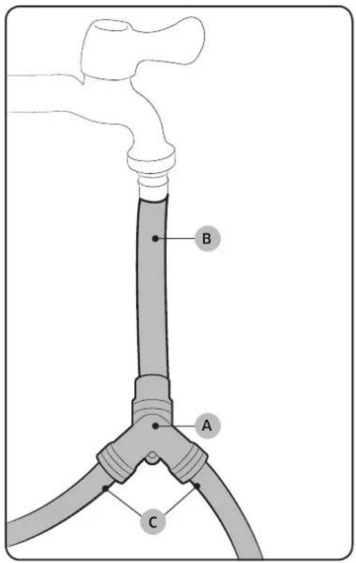
Método 2
natural_image
Illustration of a hand using a tool to adjust or install a car door panel (no text or symbols visible)
natural_image
Simple line drawing of a mechanical device with a downward arrow indicating motion or force (no text or symbols)
ADVERTENCIA
natural_image
Diagram of a mechanical assembly with cylindrical components and a belt, showing alignment and dimension (no text or symbols)
natural_image
Diagram of a refrigerator interior showing ventilation duct and door (no text or labels)
natural_image
Simple diagram showing a pipe with a wavy arrow pointing downward, no text or symbols present
natural_image
Technical line drawing of a door panel with two circular annotations highlighting internal components (no text or symbols present)
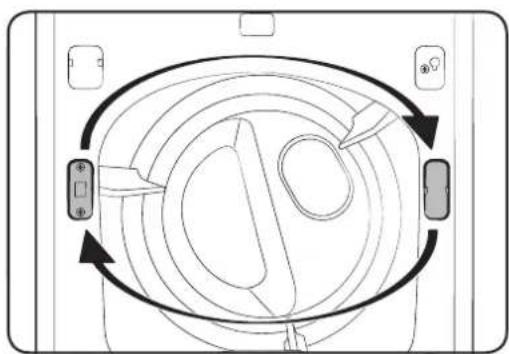
flowchart
graph TD
    A["Top Left"] --> B["Top Right"]
    B --> C["Bottom Left"]
    C --> D["Bottom Right"]
    D --> E["Top Right"]
    style A fill:#f9f,stroke:#333
    style B fill:#ccf,stroke:#333
    style C fill:#cfc,stroke:#333
    style D fill:#fcc,stroke:#333
    style E fill:#ffc,stroke:#333
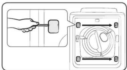
natural_image
Technical line drawing of a rectangular frame with circular components and a central oval shape, labeled 'B' (no text or symbols beyond label)
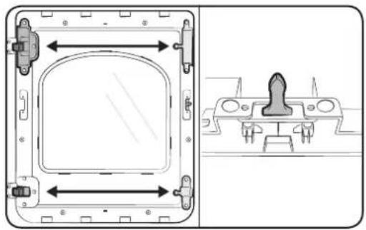
natural_image
Technical line drawing of a mechanical component with internal features and mounting brackets (no text or symbols)
natural_image
Pure technical diagram of a square component with circular features and labeled points A, B, C (no text or symbols beyond labels)
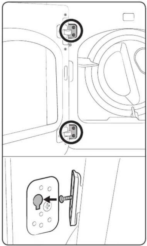
natural_image
Technical line drawing of a door panel with two circular components and a separate view showing a key inserted into a lock (no text or symbols)
natural_image
Diagram of a hand inserting a component into a device panel, showing no text or symbols present.
Ridgefield Park, NJ 07660
Samsung Electronics Canada Inc.
2050 Derry Road West
Mississauga, Ontario L5N 0B9 Canada
www.samsung.com/ca/support (English)
www.samsung.com/ca_fr/support (French)