
Due A - Coffee machine Faema - Free user manual and instructions
Find the device manual for free Due A Faema in PDF.
| Product type | Professional espresso machine |
| Brand | Faema |
| Model | Due A |
| Power supply | Single-phase or three-phase depending on configuration |
| Gas supply (optional) | LPG gas with adapted injectors |
| Pump pressure | Adjustable, approximately 9 bar |
| Boiler pressure | Indicated by pressure gauge, approximately 1 bar |
| Boiler capacity | Approximately 10 liters (estimate) |
| Dimensions (W x D x H) | Approximately 600 x 500 x 500 mm (estimate) |
| Weight | Approximately 35 kg (estimate) |
| Main functions | Espresso, long coffee, hot water, steam, cappuccino |
| Portafilters | 2 portafilters (1-shot and 2-shot) |
| Controls | Keypad with buttons for doses, stop/prog, continuous dispensing, cappuccinomatic |
| Water level | Visual indicator and automatic level probe |
| Cup warmer | Heating plate with switch |
| Maintenance | Daily cleaning of groups, portafilters, drip tray; regular descaling |
| Safety | All-pole switch, 30 mA protection, mandatory grounding, safety valve |
| Spare parts | Injectors, gaskets, portafilters, heating elements, solenoid valves, pump |
| Repairability | Authorized Faema technical assistance |
| General information | Made in Italy by FAEMA S.p.A. |
Frequently Asked Questions - Due A Faema
User questions about Due A Faema
0 question about this device. Answer the ones you know or ask your own.
Ask a new question about this device
Download the instructions for your Coffee machine in PDF format for free! Find your manual Due A - Faema and take your electronic device back in hand. On this page are published all the documents necessary for the use of your device. Due A by Faema.
USER MANUAL Due A Faema
Dear Customer, We congratulate with you for your new Faema.
With this purchase you've chosen an up to date machine, built after the most advanced principles of modern technology, a unit, which gives you not only a perfect synthesis of efficiency and functionality, but puts also at your disposal everything you need for a good working.
The advice we give you of spending a bit of your time in reading this manual comes from our desire of helping you in reaching a good knowledge of your new machine.
We're sure of finding you of the same advice. With our best wishes of a good work.
FAEMA SpA
F
Cher Client,
Read the instructions in this manual carefully before using or handling the machine in any way. The instructions provide important information regarding the safety precautions to be followed.
The coffee machine is to be used solely for preparing expresso.
coffee and hot drinks made with hot water or steam and for heating
cups.
Improper use of the machine for operations other than the above can constitute a safety risk to persons and to the equipment.
The producer disclaims all liability in case of damage due to improper use of the coffee machine.
1 Main ON/OFF switch
2 Pushbutton Panel
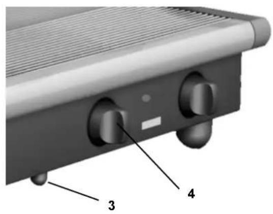
3 Piezoelectric lighter push-button (^)
4 Gas tap knob ()
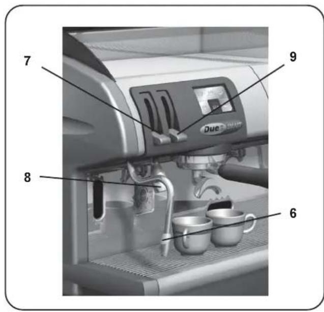
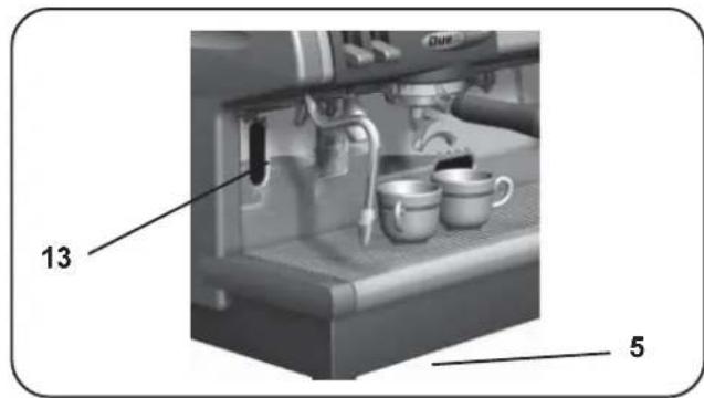
5 Boiler water filling lever
6 Swivel steam jet pipe
7 Steam adjustment lever
8 Hot water dispensing pipe
9 Hot water dispensing lever
10 Filter holder
11 Machine On light
12 Cup heating switch
13 Boiler water level indicator
14 Boiler pressure gauge
15 Pan
16 Dispensing push button - 1 short coffee
17 Dispensing push button - 2 short coffees
18 STOP/Prog - push button
19 Dispensing push button - 1 long coffee
20 Dispensing push button - 2 long coffees
21 Continual dispensing - push button
22 Cappuccino maker lever
23 Cappuccino maker #
(") only on machine "G"
Items marked - # - are fitted in some product configurations only.
LEGENDE
Installation, disassembly and setting should be carried out by qualified technical personnel only.


ATTENTION
- Carefully read the instruction herein, which contain important information for safe installation, use and maintenance. Keep this booklet on hand for further reference.
- This appliance shall only be used for its specific purpose. The manufacturers shall not be liable for damages due to improper, wrong or unreasonable use.
- Unpack and check machine for soundness. Do not leave packaging components (plastic bags, expanded polystyrene, nails, etc.) within children's reach, as they represent potential hazards.
- Prior to plugging in, check that nameplate data correspond with those of the electric and water mains.
- The coffee machine should be placed on a stable flat surface with the bodywork at a minimum distance of 20mm from the supporting surface and the walls. Furthermore, it must be installed taking into account that the highest shelf (cup warmer) must sit at a height that is at least 1.5 meters.
- The (electricity and water) supply connections and a water outlet fitted with a siphon should be close to the machine. A support surface should also be available for accessories.
-
Install an omnipolar switch with minimum 3 mm. gap between contacts and 30mA dispersion-current protection.
-
This appliance is electrically safe only when properly earthed as a set forth in the current electric safety specifications. Check for compliance and, when in doubt, have the wiring thoroughly inspected by skilled personnel. The manufacturers shall not be liable for any damage caused by faulty earting.
- Using adapters, multiple plugs and cable extensions is not recommended. Should they be indispensable, use simple or multiple adapters and extensions that comply with the current safety regulations, take care not to exceed the limit current load shown on simple adapters and extensions, and the limit power load shown on multiple adapters.
- To prevent dangerous overheating, uncoil the power cable to its full length.
- To ensure correct operation and safety, the coffee machine should not be exposed to outdoor weather conditions (rain, sun, ice).
- Do not install in rooms (kitchens) cleaned using water jets.
- Do not plug or clog the ventilation and heat-exhausting louvres.
- If the machine's electrical cord is damaged, it should be replaced. This should only be done by an authorized service technician.
- If the machine is stored on premises where the temperature may drop below freezing point, always empty the boiler and the water circulation pipes
Installazione - Installation - Installation - Installation - Instalación - Instalación


INDICATIONS POUR L'INSTALLATION
INDICACOsParaAINSTALACAO
The equipment does not exceed 70dB
Omnipolar switch with 3 mm contact opening
30 mA dispersion-current protection
INTERRUPTEUR:
(for pressure beyond this value, install a pressure reducer)
Place the machine on a perfectly levelled surface, adjusting and then fixing the feet in place.
Make the hydraulic connections as per Figure.
Install the drain siphon in the water-drain line so that it is easily accessible and will thus facilitate periodic cleaning.
Remember to put the relevant washer in the junctions between the tubes and the connectors.
If water hardness is higher than 8^ F, it is advised to install a water softener. For the choice, please comply with local hygiene laws. If the machine is fed with water with a hardness of over 8^ F, specific maintenance plan must be implemented to ensure correct functioning of the machine.
The amount of chlorine in the water must not exceed 100 mg/l; otherwise, install the appropriate devices.
N. B.: If the main pressure could rise above 6 bar, install a pressure reducer calibrated at 2 ÷ 3 bar before the softener.
F CONNECTION HYDRAULIQUE
Before making the connection, verify that the electric wiring prepared by the customer follows the current regulations and that it has been eared according to regulations. Remember that Faema Spa is not responsible for damages due to incorrect electrical connections and, furthermore, that the installer is responsible in case of damage.
Besides the above, check:
- the type of connection indicated on the label found on the power cable.
- that the voltage corresponds to that indicated on the nameplate data found on the box cover.
The machines are planned for these connections: normally Y (fig. 1).
- If the connection between (Y) and (Δ) needs to be changed, follow the instructions in the diagrams in Figure 2.
The machines with single phase connection have a special wiring system (see UL).
F BRANCHEMENT ELECTRIQUE
Wires colour for UL machines only
sColor cables - Cor cabos
bl Azzurro - Blue - Bleu la Baequete Azul - Azul
B White
Grigio (Nero) - Grey (Black) Gris (Noir) - Grau (Schwarz) Gris (Negro) - Cinza (Preto)
T Black
ma Marrone - Brown - Brun Braun - Maron - Marron
ne Nero-Black-Noir Schwarz-Negro-Preto
Installazione - Installation - Installation - Installation - Instalación - Instalación
D STROMANSCHLUSS
Wires colour for UL machines only
pl calzuzne -Blue-Bleu Blau-Azul-Azul
B White
gros Grigio (Nero)-Grey (Black) Gris (Noir)- Grau (Schwarz) Gris (Negro)-Cinza (Preto)
T Black
ma Marrone - Brown - Brun Braun - Maron - Marron
ne Nero-Black-Noir Schwarz-Negro-Preto
Installazione - Installation - Installation - Installation - Instalación - Instalación
COLLEGAMENTO EQUIPOTENZIALE
This connection, which is the one called for by several norms, avoids electrical potential differences building up between any equipment that may be installed in the same room.
There is a terminal clip on the under side of the base of the machine to which an external potential equalizing wire should be connected.
This connection is ABSOLUTELY NECESSARY and must be made right after the machine is installed.
-
Use a wire whose cross-sectional area conforms to
-
Make the terminal connection (see diagram) and then end to the ground connections located on the adjacent equipment.
Failure to do observe these safety precautions will exempt the manufacturer from any responsibility as regards damage caused to persons or property. NOTE: DO NOT CONNECT THE MACHINE'S TERMINAL CLIP TO THE MAINS GROUND TERMINAL BECAUSE THE GROUND TERMINAL OF ANY MAIN SOURCE OF ELECTRICAL POWER IS NOT CONSIDERED TO BE A POTENTIAL-EQUALIZING CONNECTION.
D STROMANSCHLUSS MIT POTENTIALAUSGLEICH
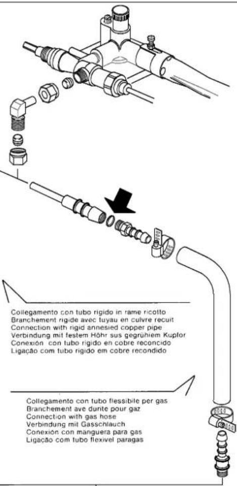
GB GAS CONNECTION (only for models with ^+ GAS)
Keeping local regulations in mind, the connection to gas tubig can be done with either a rigid tube or a flexible tube, see Figure. For installation with flexible tube:
- Two hose-adaptor connectors, with differing dimensions according to the type of gas used, are supplied for the installation of the tube. The connectors conform to safety norms.
- Block the tube on the hose-adapter connectors with clamps conform to the safety norms.
Once the connection is made, check for possible gas leaks with a soapy solution and eliminate them. We remind you that any improper functioning of the installation is the responsibility of the installer.
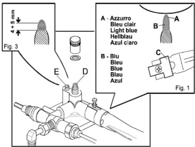
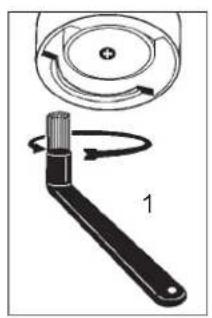
Substitute injectors
The machine is prepared for the use of GPL (liquid propane gas), that is, it has an injector and self-adjuster installed and calibrated in the factory for that type of gas. If the gas is of a different type, the injector "A" must be replaced with a suitable injector;
- disconnect the burner block spring.
- let the burner slide after having loosened screw "B".
- replace the injector with the suitable one. See table.
- reposition the parts, remembering to reconnect the burner
favorile
Collegamento con tubo fiessible per gas Branchement ave dune pour gaz Connection with gas hose Verbindung mit Gasschlauch Conexion con manguera para gas Ligacao com tubo flexivel paragas
spondenti

block spring.
GB PIEZOELECTRIC GAS IGNITION (only for models with ^+ GAS)
Open the gas tap.
Press and turn the gas tap knob (4) counter-clockwise and repeatedly press the piezoelectric switch-on push-button (3) until the burner under the boiler lights up.
Check through the observation window that the burner is lit and, after a few seconds, release the knob (4).
GSCONNECTION TO GAS HEATING (only for models with ^+ GAS)
Adjustment of the combustion
- The flame must be blue. It should not be detached from the burner and should not be yellowish around the edges.
- Position the air lock C at the right moment.
- The height of the flame must be as shown in figure 1.
Adjustment of the flame in operation
- Adjust screw D.
- The calibration must be less than that imposed for the pressuredstat.
Adjustment of the operating minimum
- Adjust screw E.
- The height of the flame must be as shown in figure 3.

For correct operation, check these conditions:
1) HYDRAULIC CONNECTION
Absence of leaks from the connection or from the tubes
2) GAS CONNECTION
Absence of leaks
Correct combustion
3) OPERATION
Antisuction valve seal
Boiler pressure and operating pressure in conformity with normal
values
Correct functioning of the pressurestat
Correct functioning of the gas pressurestat (when there is one)
Correct functioning of the autolevel
Correct functioning of the expansion valve
Check of the water output of the group
Dose check
Temperature check of the hot water output
Check of the ground doses and of the functioning of the coffee
grinder

CHECK-UP FONCTIONNEMENT
Tenue valve anti-remous
- Connect the (empty) filter-holders to the dispenser units.
- Dispense water from each dispenser for about one minute.
ACQUA CALDA
cordisperse hot water repeatedly (using the relative command) until at least 4 liters of water have been dispensed from the 1-group machine, 6 liters of water from the 2-group machine and 9 liters from the 3-group machine.
VAPORE
- Allow the steam to flow through the nozzles for approximately minute, using the appropriate commands.
NOTE: See the instructions in the USE and MAINTENANCE MANUAL for dispensing water, hot water and steam.
F

ATTENTION: UNE FOIS TERMINÉ L'INSTALLATION ET AVANT DE COMMENCER À UTILISER LA MACHINE, EFFECTUER UN LAVAGE DES COMPOSANTS INTERNES EN SUIVANT LES INDICATIONS REPORTÉS CI-APRès.
D

Gas installation switch-on
(for "G" machines only)
Heating phase
Delivery of the coffee
Other hot beverages
Programming the coffee measures
Water level control of boiler
Cleaning and maintenance
Cautions
Defects - Malfunctions
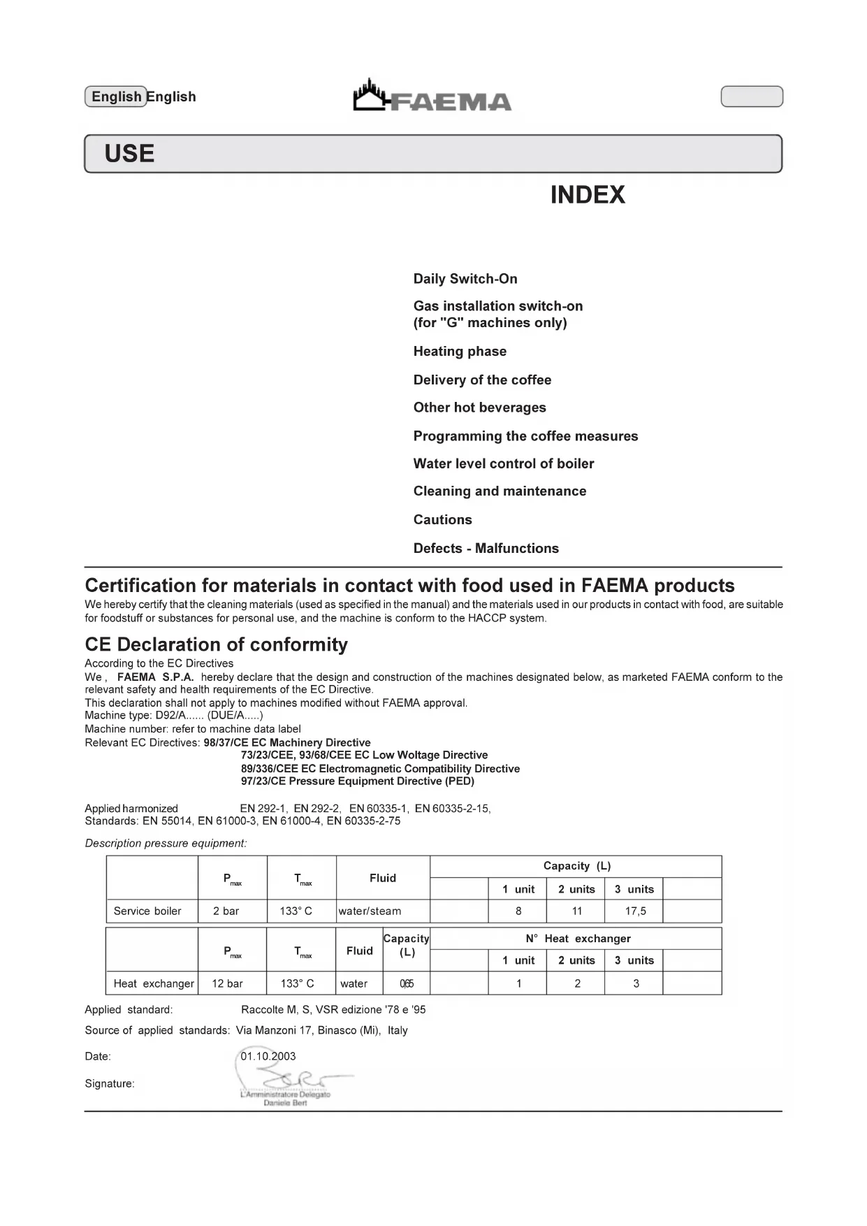
Certification for materials in contact with food used in FAEMA products
We hereby certify that the cleaning materials (used as specified in the manual) and the materials used in our products in contact with food, are suitable for foodstuff or substances for personal use, and the machine is conform to the HACCP system.
CE Declaration of conformity
According to the EC Directives
We, FAEMA S.P.A. hereby declare that the design and construction of the machines designated below, as marketed FAEMA conform to the relevant safety and health requirements of the EC Directive.
This declaration shall not apply to machines modified without FAEMA approval.
Machine type: D92/A.... (DUE/A....)
Machine number: refer to machine data label
Relevant EC Directives: 98/37/CE EC Machinery Directive
73/23/CEE, 93/68/CEE EC Low Voltage Directive
89/336/CEE EC Electromagnetic Compatibility Directive
97/23/CE Pressure Equipment Directive (PED)
Applied harmonized
EN 292-1, EN 292-2, EN 60335-1, EN 60335-2-15
Standards: EN 55014, EN 61000-3, EN 61000-4, EN 60335-2-75
Description pressure equipment:
| Pmax | Tmax | Fluid | Capacity (L) | |||||
| 1 unit | 2 units | 3 units | ||||||
| Service boiler | 2 bar | 133°C | water/steam | 8 | 11 | 17,5 | ||
| Pmax | Tmax | Fluid | Capacity (L) | N° Heat exchanger | |||||
| 1 unit | 2 units | 3 units | |||||||
| Heat exchanger | 12 bar | 133°C | water | 0.65 | 1 | 2 | 3 | ||
Applied standard:
Source of applied standards: Via Manzoni 17, Binasco (Mi), Italy
Date:
Signature:
01.10.2003

Daily Switch-On

Before using the machine make sure that: the main electricity supply ON/OFF switch is ON; the water supply and water softener taps are open.
Turn the main switch (1) to position 1. The boiler is filled until the set level is reached. Turn the main ON/OFF switch (1) to position 2. "Heating" now begins.
At the end of the day, turn the machine OFF by turning the main ON/OFF switch (1) to position 0.
Gas installation switch-on (for "G" machines only)

"Don't switch on the gas installation when the boiler is under pressure".
Before using the machine check that:
- the main electricity supply ON/OFF switch is ON;
- the main water supply tap is open.
- the gas supply tap is open.
Turn the main switch ON/OFF (1) to position 1
The machine completes the operations described under "Daily Switch-on".
Press and turn the gas tap knob (4) counter-clockwise and repeatedly press the piezoelectric switch-on push-button (3) until the burner under the boiler lights up.
Check through the observation window that the burner is lit and, after a few seconds, release the knob (4).
"Heating" now begins.
At the end of the day, switch off the machine by turning the ON/OFF switch (1) to the "0" position and close the gas tap (4) by turning it to the "0" position.
Heating phase
During heating, if one of the coffee dispensing push buttons (16, 17, 19, 20, 21) is pressed, the machine dispenses a coffee at the temperature reached at the time.
Heating is completed when the boiler gauge indicator (14) remains stable in the green area.
The machine is now ready to dispense coffee, steam and hot water. To make sure that the dispenser unit and the filter holder (10) are at similar temperatures, press the coffee dispensing push button (21) and let the machine dispense coffee for a few seconds. Then press the STOP push button (18) to stop dispensing.
Delivery of the coffee
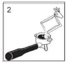
Remove the filter holder (10), empty out any coffee grouts and fill it up with 1 or 2 servings of ground coffee, depending on the filter holder used.
Press the ground coffee in filter down uniformly, using the grinder/doser presser.
Remove any residues of ground coffee from the filter rim.
Fit and tighten the filter holder (10) on the coffee dispenser unit, positioning the cup (or cups) under the nozzle (or nozzles) of the filter holder (10).
Press the coffee dispensing push button (16, 17, 19, 20) for the required serving; the machine will stop automatically.
Press the push button (21) for continuous dispensing.
Dispensing, whether for dosed servings or in the continuous dispensing mode, can be interrupted at any time by pressing the STOP push button (18).

Other hot beverage
Steam dispensing
Put a cup with the beverage you wish to heat under the right or left steam nozzle (6).
Completely immerse the steam nozzle in the beverage.
Push the steam control lever (7) upward, allow the beverage to heat to the desired temperature, then lower the control lever.
Heating milk for frothy coffee (cappuccino)
Use a tall narrow jug and fill it up to about the half-way mark. Then plunge the steam jet pipe (6) into the milk.
Gradually open up the steam tap (7) and heat the milk for a few seconds. When the required amount of froth has been made and the temperature is sufficiently high, stop the flow of steam by turning knob (7) the other way (towards "0").
When the steam jet pipe (6) is no longer required, clean it thoroughly with a sponge and a clean cloth.
Dispensing hot water
Put a cup or other container under the hot water spout (8).
Lift lever (9) to dispense the desired amount of hot water.
Stop the dispensing by put lever (9) back into its original position.
Note: At the conclusion of each steam dispensing phase, clean the inside of the steam nozzle as follows: Turn the nozzle towards the cup tray and carefully activate steam dispensing at least once.
Programming the coffee measures
How to access the programming function
To enter the programming mode, press STOP/progr button (18) and keep it pressed for a few seconds; the buzzer sounds intermittently. To exit the programming mode, after programming the various drinks, press STOP/progr button (18) again.

Before programming the coffee dispensing push buttons fill the filter holder with the correct serving of ground coffee. Don't use coffee grouts for programming servings.
Fit and tighten the filter holder (10) on the coffee dispenser unit, positioning the cup (or cups) under the nozzle (or nozzles) of the filter holder (10). Press (and keep momentarily pressed) the coffee dispensing push button (16, 17, 19 or 20) corresponding to the required serving to be programmed. When the amount of coffee in the cup reaches the required level, release the coffee dispensing push button.
Repeat the above operations for the other coffee push buttons. Note: if you make a programming mistake, use a new dose of ground coffee and repeat the operation.

Water level control of boiler
The machine is fitted with a series of automatic level control devices to keep the water in the boiler at a pre-set level.
Filling the boiler with water using the manual service tap
This function should be used only if the electronic level control devices are not working correctly.
Press the filling lever (5), taking care not to exceed the MAX. level on the boiler water level indicator (13).
Cleaning and maintenance
Cleaning dispensing unit
This operation must be made on all the groups at the end of each working day
1) Using a brush, clean the cover gasket.
2) Insert the rubber disk into the filter-holder with its filter.
3) Pour in a packet or dosing cupful of detergent powder
4) Insert the filter carrier into the group and press the selection button. After a few seconds, press the STOP button. Repeat this operation a few times.
5) Remove the filter-holder and clean the shower with a sponge.
6) Flush each dispenser unit with water for about 30 seconds.
Filter-holders
1) Put a liter of cold water in a suitable container and add detergent.
2) Soak the filter-holders in this solution for about 2 hours.
3) Remove the filters from the filter-holders and wash the parts in the same detergent solution, using a small sponge.
4) Flush thoroughly with cold water.
5) Reinstall the filters in the filter-holders, making sure that filter-retainer spring seats properly.
Steam and hot water dispensing pipes
Using a clean sponge, wash with hot water removing any organic residue present. Rinse carefully.
To clean the inside of the steam nozzle, follow these steps:
Turn the nozzle towards the cup tray and carefully activate steam dispensing at least once.
Grille and Drip Basin
Remove the grille from the basin, extract the grille sections and complete the cleaning operation under running water.
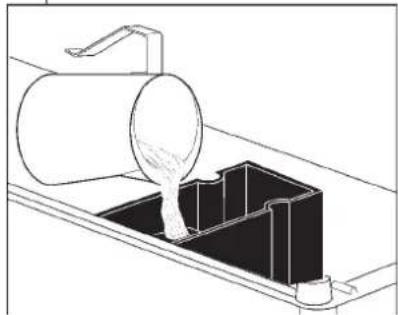
Discharge Basin
At the end of the working day, pour about a liter of hot water into it to remove any discharge residues.

Bodywork
Use a soft cloth and cleaning products WITHOUT ammonia or abrasives, removing any organic residue present in the work area. N.B. Do not spray liquids into the panel slots.

ATTENTION
When the machine has not been used for more than 8 hours, and in any case once a day, the internal components must be washed before use, in accordance to the following instructions:
Supply Groups
Insert the filter carriers into the groups (without coffee) and dispense from each group for one minute.
Hot water
Dispense hot water repeatedly (using the relative command) until at least 4 liters of water have been dispensed from the 1-group machine, 6 liters of water from the 2-group machine and 9 liters from the 3-group machine.
Steam
Allow the steam to flow for approximately one minute, using the appropriate commands.
Cautions

Danger of burns
The areas marked with this sign become hot. Great care should be taken when in the vicinity of these areas.
WARNING: Hot surface
ACHTUNG: Heisse Oberfläche
ATTENTION: Surface chaude
ATTENZIONE: Superficie calda
GENERAL
Use of gas operated appliances in premises smaller than 12 m^2 is not permitted.
If a gas heated installation is used, change the flexible tube at the due expiry date.
The manufacturer disclaims all liability for damages to items or persons due to improper use or due to the coffee machine being used for reasons other than its intended use.
Never work the coffee machine with wet hands or naked feet.
Cup-warming plate
Place only coffee cups, cups and glasses to be used in conjunction with the coffee machine on the cup-warming plate.
Ensure that the coffee cups are completely drained before placing them on the cup-warming plate.
No other objects shall be placed on the cup-warming plate.

MACHINE CLOSE-DOWN
When the machine remains unattended for a long period of time (at night, during the weekly closing day or during holidays) the following operations shall be performed:
- Remove the plug or switch off the main switch.
- Close the water tap.
- Close the gas tap.
Non-compliance with these safety measures exonerates the manufacturer from all liability for malfunctions or damage to persons or items.
Danger of Burns
Do not place the hands or other parts of the body close to the coffee distribution points, or near to the steam and hot water nozzles.
Ensure that the machine is not handled by children or persons who have not been instructed in its correct use.
MAINTENANCE AND REPAIR
If the machine does not function correctly, switch it off, turn off the main switch and call the service agent.
Only qualified and authorised servicing personnel should be called.
Use only original spare parts.
Maintenance activities performed by unqualified personnel may jeopardise the safety of the machine.
If the electric cable is damaged, switch off the machine and apply to the servicing department for a replacement.

The following measures are indispensable for ensuring operational and functional safety:
- Comply with all the manufacturer's instructions.
- Ensure that specialized technicians periodically verify that the protection devices are intact and that all the safety devices function correctly (the first inspection should be made within 3 years and subsequently once yearly).
Regeneration of the Water Softener
The machine must be installed with an ionic resin water softener.
The water softener may be of different types, with different resin capacities and different periods of validity.
The resins are regenerated by adding coarse kitchen salt or salt pastilles to the water softener.
If the regeneration of the resins is not made at the due dates, calcareous deposits will form which progressively decrease the machine's efficiency until its functions are completely blocked.
The regeneration due dates and method thereof may be found in the instructions provided with the equipment.
If regeneration is performed at the due dates, the machine is maintained in ideal working conditions.
Defects - Malfunctions
Direct action by the customer
Before calling service personnel, to avoid useless expense, check whether the machine problem corresponds to one of the cases listed below.
| PROBLEM | CAUSE | SOLUTION |
| The coffee machine is not working. | No electricity supply. | Check the electricity supply. Check the position of the ON/OFF switch (1). |
| The coffee machine is not heating up. | ON/OFF switch (1) position incorrect. | Turn the ON/OFF switch (1) to position 2. |
| Leaking from the filter holder rim (10). | Underpan gasket dirty with coffee. | Clean using the special brush provided. |
| Coffee dispensing time too short. Use a finer grind. Coffee ground too coarse. Coffee too old. | Use new coffee. | |
| Coffee drips out of machine. Clean. | Filter holes blocked or filter holder (10) outlet hole dirty. Coffee ground too fine. | Use a coarser grind. |
| Loss of water under the machine. Clean. | Discharge well clogged up. Discharge pan hole blocked. | Clean. |
| Machine heated up, but it does not dispense coffee. | Water supply or water softener tap closed. No water in system. | Open. Wait until water is available or call a plumber. |
Schema elektrico - Wiring diagram - Schema elektrique Elektrischer Schaltplan - Esquema elektrico - Esquema elektrico

1
LEGENDALEGEND
1 = Main switch
2 = ON-OFF pilot lamp
5 = Cup-heater switch
8 = D i p - s w i t c h
10 = Main electronic board
1 = Button board
7 = Level probe
19 = Level solenoid valve
= Group 1 solenoid valve
21 = Group 2 solenoid valve
22 = Group 3 solenoid valve
26 = Pump motor
27 = Pump capacitor
28 = Cup-heater thermostat
29 = Cup-heater heating element
30 = Pressure switch
31 = Boiler heating element
32 = Turbine led
33 = Boiler thermal cut-out
34 = Turbine
36 = Cup-heater thermal cut-out
38 = Pump fuses
39 = Setup jumpers
* 41 = Water mixer switch
Items marked - * - are fitted in some product configurations only.
F
LEGENDE
1 = Pump pressure gauge
2 = Pump filter
3 = Pump
4 = Pump pressure regulator
5 = Non return valve (heat exch.)
6 = Expansion valve
8 = Turbine
9 = Boiler
10 = Safety valve
11 =Vacuum release valve
12 = Coffee dispenser group
13 = Coffee solenoid valve
14 = Thermosiphon circuit neck
15 = Boiler non return valve
18 = Hot water tape
19 = Water filling manual valve
20 = Pin-tap for solenoid value
21 = Automatic filling solenoid valve
22 = Automatic filling neck
23 = Steam tape
26 = Pressure switch
27 = Level indicator
29 = Boiler pressure gauge
30 = Modulating governor
31 = Heat exchangers
32 = Automatic level probe
33 = Dispenser group injector
34 = Safety valve (Spain only)
Items marked - * - are fitted in some product configurations only.
F
LEGENDE
Copyright by FAEMA S.p.A., Milano
FAEMA reserves the right to make changes to the machines in accordance with the needs of individual countries and on the basis of technological progresses.
This publication may not, either in whole or in part, be used, copied or published without the written authorisation of FAEMA S.p.A.
Copyright by FAEMA S.p.A., Milan, Italy
All rights reserved

FAEMA S.p.A.
Via Manzoni, 17
20082 Binasco
(MI) Italy
Tel: +39-2-90.04.81
Fax: +39-2-90.54.818
www.faema.it
Copyright by FAEMA S.p.A., Milano
Copyright by FAEMA S.p.A., Milano
Copyright by FAEMA S.p.A., Milan
Todoosderechosestanreservados

FAEMA S.p.A.
Via Manzoni, 17
20082 Binasco
(MI) Italy
Tel: +39-2-90.04.81
Fax: +39-2-90.54.818
www.faema.it
Copyright by FAEMA S.p.A., Milano
FAEMA and the "SERVICE LINE"
The FAEMA Company's client service, the aim of which is to assure top coffee-machine performance for its clients at all times, also makes available its ECO LINE, a series of specific cleaning products expressly designed for this purpose.
ECO LINE - Cleaning products
A) For cappuccino makers in liquid form 4991-134458;
B) For dispensers, filter-holders, coffee cups in powder form 4991-134682;
C) For dispensers, filter-holders, coffee cups in small envelopes 4991-134681;
D) For superautomatic-machine dispensers in tablet form 4991-134683.
Order directly from your local distributor and refer to the particular item you require by its number, as shown above.

FAEMA et la "SERVICE LINE"

- F
- LEGENDE
- ATTENTION
- Installazione - Installation - Installation - Installation - Instalación - Instalación
- INDICATIONS POUR L'INSTALLATION
- INDICACOsParaAINSTALACAO
- F CONNECTION HYDRAULIQUE
- F BRANCHEMENT ELECTRIQUE
- D STROMANSCHLUSS
- COLLEGAMENTO EQUIPOTENZIALE
- D STROMANSCHLUSS MIT POTENTIALAUSGLEICH
- GB GAS CONNECTION (only for models with + GAS)
- Substitute injectors
- GB PIEZOELECTRIC GAS IGNITION (only for models with + GAS)
- GSCONNECTION TO GAS HEATING (only for models with + GAS)
- Adjustment of the combustion
- Adjustment of the flame in operation
- Adjustment of the operating minimum
- CHECK-UP FONCTIONNEMENT
- ACQUA CALDA
- VAPORE
- D
- Certification for materials in contact with food used in FAEMA products
- CE Declaration of conformity
- Daily Switch-On
- Gas installation switch-on (for "G" machines only)
- Heating phase
- Delivery of the coffee
- Other hot beverage
- Steam dispensing
- Heating milk for frothy coffee (cappuccino)
- Dispensing hot water
- Programming the coffee measures
- How to access the programming function
- Water level control of boiler
- Filling the boiler with water using the manual service tap
- Cleaning and maintenance
- Cleaning dispensing unit
- Filter-holders
- Steam and hot water dispensing pipes
- Grille and Drip Basin
- Discharge Basin
- Bodywork
- Supply Groups
- Hot water
- Steam
- Cautions
- Danger of burns
- GENERAL
- Cup-warming plate
- MACHINE CLOSE-DOWN
- MAINTENANCE AND REPAIR
- Regeneration of the Water Softener
- Defects - Malfunctions
- Direct action by the customer
- Schema elektrico - Wiring diagram - Schema elektrique Elektrischer Schaltplan - Esquema elektrico - Esquema elektrico
- LEGENDALEGEND
- FAEMA and the "SERVICE LINE"
- FAEMA et la "SERVICE LINE"
Brand : Faema
Model : Due A
Category : Coffee machine