
E61 3 GR - Coffee machine Faema - Free user manual and instructions
Find the device manual for free E61 3 GR Faema in PDF.
| Product Type | Professional espresso machine |
| Brand | Faema |
| Model | E61 3 GR |
| Number of groups | 3 |
| Electrical supply | Single phase 230 V / 50 Hz (check nameplate) |
| Boiler pressure | 1 to 1.5 bar |
| Pump pressure | 9 to 12 bar |
| Boiler capacity | Approximately 11 liters |
| Material | Stainless steel |
| Dimensions (L x D x H) | Approximately 800 x 500 x 500 mm |
| Weight | Approximately 70 kg |
| Main functions | Espresso preparation, hot water, steam, cup warmer |
| Safety | Omnipolar switch, 30 mA protection, grounding, safety valve, thermostat |
| Maintenance and cleaning | Daily cleaning of groups and portafilters, boiler rinse, descaling according to water hardness |
| Spare parts and repairability | Portafilters, gaskets, filters, steam wand, parts available through authorized dealer |
| General information | Manual downloadable for free, FAEMA technical support |
Frequently Asked Questions - E61 3 GR Faema
User questions about E61 3 GR Faema
0 question about this device. Answer the ones you know or ask your own.
Ask a new question about this device
Download the instructions for your Coffee machine in PDF format for free! Find your manual E61 3 GR - Faema and take your electronic device back in hand. On this page are published all the documents necessary for the use of your device. E61 3 GR by Faema.
USER MANUAL E61 3 GR Faema
We congratulate with you for your new Faema.
With this purchase you've chosen an up to date machine, built after the most advanced principles of modern technology, a unit, which gives you not only a perfect synthesis of efficiency and functionality, but puts also at your disposal everything you need for a good working. The advice we give you of spending a bit of your time in reading this manual comes from our desire of helping you in reaching a good knowledge of your new machine.
We're sure of finding you of the same advice.
With our best wishes of a good work.
FAEMA SpA

Read the instructions in this manual carefully before using or handling the machine in any way. The instructions provide important information regarding the safety precautions to be followed.
The coffee machine is to be used solely for preparing expresso coffee and hot drinks made with hot water or steam and for heating cups.
Improper use of the machine for operations other than the above can constitute a safety risk to persons and to the equipment.
The producer disclaims all liability in case of damage due to improper use of the coffee machine.
D
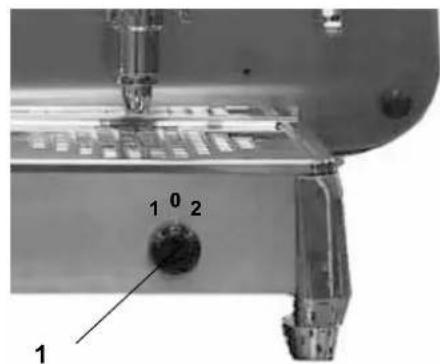
1 Main ON/OFF switch
2 Coffee dispensing lever
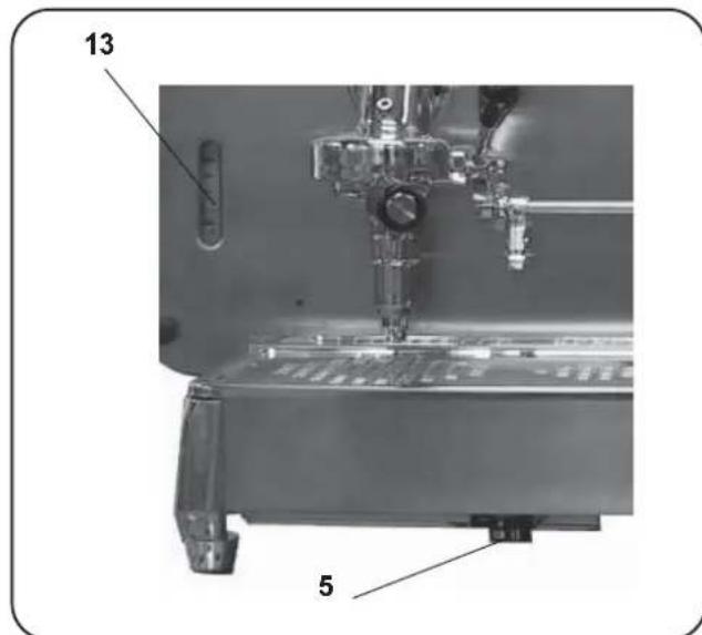
5 Boiler water filling lever
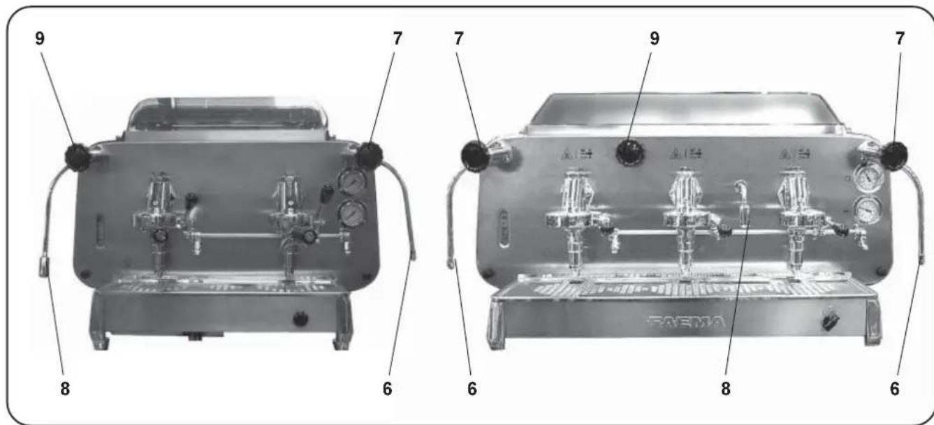
6 Steam jet pipe
7 Steam adjustment knob
8 Hot water dispensing pipe
9 Hot water dispensing knob
10 Filter holder
13 Boiler water level indicator
14 Boiler pressure gauge
15 Pan
16 Pressure gauge pump
17 Cup warmer tray
18 Backlit glass switch
19 Backlit glass
F LEGENDE
Installation - Installation - Installation - Installation - Instalación - Instalação

ATTENZIONE
Installation, disassembly and setting should be carried out by qualified technical personnel only.

ATTENTION
- Carefully read the instruction herein, which contain important information for safe installation, use and maintenance. Keep this booklet on hand for further reference.
- This appliance shall only be used for its specific purpose. The manufacturers shall not be liable for damages due to improper, wrong or unreasonable use.
- Unpack and check machine for soundness. Do not leave packaging components (plastic bags, expanded polystyrene, nails, etc.) within children's reach, as they represent potential hazards.
- Prior to plugging in, check that nameplate data correspond with those of the electric and water mains.
- The coffee machine should be placed on a stable flat surface with the bodywork at a minimum distance of 20mm from the supporting surface and the walls. Furthermore, it must be installed taking into account that the highest shelf (cup warmer) must sit at a height that is at least 1.5 meters.
- The (electricity and water) supply connections and a water outlet fitted with a siphon should be close to the machine. A support surface should also be available for accessories.
-
Install an omnipolar switch with minimum 3mm gap between contacts and 30mA dispersion-current protection.
-
This appliance is electrically safe only when properly earthed as set forth in the current electric safety specifications. Check for compliance and, when in doubt, have the wiring thoroughly inspected by skilled personnel. The manufacturers shall not be liable for any damage caused by faulty earting.
- Using adapters, multiple plugs and cable extensions is not recommended. Should they be indispensable, use simple or multiple adapters and extensions that comply with the current safety regulations, take care not to exceed the limit current load shown on simple adapters and extensions, and the limit power load shown on multiple adapters.
- To prevent dangerous overheating, uncoil the power cable to its full length.
- To ensure correct operation and safety, the coffee machine should not be exposed to outdoor weather conditions (rain, sun, ice).
- Do not install in rooms (kitchens) cleaned using water jets.
- Do not plug or clog the ventilation and heat-exhausting louvres.
- If the machine's electrical cord is damaged, it should be replaced. This should only be done by an authorized service technician.
- If the machine is stored on premises where the temperature may drop below freezing point, always empty the boiler and the water circulation pipes
Installazione - Installation - Installation - Installation - Instalación - Instalación


INDICATIONS POUR L'INSTALLATION
INDICACOsParaAINSTALACAO
NOISE The equipment does not exceed 70dB
(for pressure beyond this value, install a pressure reducer)
Place the machine on a perfectly levelled surface, adjusting and then fixing the feet in place.
Make the hydraulic connections as per Figure.
Install the drain siphon in the water-drain line so that it is easily accessible and will thus facilitate periodic cleaning.
Remember to put the relevant washer in the junctions between the tubes and the connectors.
If water hardness is higher than 8^ F, it is advised to install a water softener. For the choice, please comply with local hygiene laws.
If the machine is fed with water with a hardness of over 8^ F, specific maintenance plan must be implemented to ensure correct functioning of the machine.
The amount of chlorine in the water must not exceed 100mg / l otherwise, install the appropriate devices.
N. B.: If the main pressure could rise above 6 bar, install a pressure reducer calibrated at 2 ÷ 3 bar before the softener.
F
CONNECTION HYDRAULIQUE
Before making the connection, verify that the electric wiring prepared by the customer follows the current regulations and that it has been eared according to regulations. Remember that Faema Spa is not responsible for damages due to incorrect electrical connections and, furthermore, that the installer is responsible in case of damage.
Besides the above, check:
- the type of connection indicated on the label found on the power cable.
- that the voltage corresponds to that indicated on the nameplate data found on the box cover.
The machines are planned for these connections: normally Y (fig. 1).
- If the connection between (Y) and (Δ) needs to be changed, follow the instructions in the diagrams in Figure 2.
The machines with single phase connection have a special wiring system (see UL).
F BRANCHEMENT ELECTRIQUE
Wires colour for UL machines only
sColor cables - Cor cabos
bl Azzurro - Blue - Bleu la Baequete Azul - Azul
B White
Grigio (Nero) - Grey (Black) Gris (Noir) - Grau (Schwarz) Gris (Negro) - Cinza (Preto)
T Black
ma Marrone - Brown - Brun Braun - Maron - Marron
ne Nero-Black-Noir Schwarz-Negro-Preto
Installazione - Installation - Installation - Installation - Instalacion - Instalacao
D STROMANSCHLUSS
Wires colour for UL machines only
epi cabzuge - Blue - Bleu Blau - Azul - Azul
B White
dos Grigio (Nero)-Grey (Black) Gris (Noir)-Grau (Schwarz) Gris (Negro)-Cinza (Preto)
T Black
ma Marrone - Brown - Brun Braun - Maron - Marron
ne Nero-Black-Noir Schwarz-Negro-Preto
Installazione - Installation - Installation - Installation - Instalación - Instalación
COLLEGAMENTO EQUIPOTENZIALE
This connection, which is the one called for by several norms, avoids electrical potential differences building up between any equipment that may be installed in the same room.
There is a terminal clip on the under side of the base of the machine to which an external potential-equalizing wire should be connected.
This connection is ABSOLUTELY NECESSARY and must be made right after the machine is installed.
-
Use a wire whose cross-sectional area conforms to the existing norms.
-
Make the terminal connection (see diagram) and then connect the other end to the ground connections located on the adjacent equipment.
Failure to do observe these safety precautions will exempt the manufacturer from any responsibility as regards damage caused to persons or property.
NOTE: DO NOT CONNECT THE MACHINE'S TERMINAL CLIP TO THE MAINS GROUND TERMINAL BECAUSE THE GROUND TERMINAL OF ANY MAIN SOURCE OF ELECTRICAL POWER IS NOT CONSIDERED TO BE A POTENTIAL-EQUALIZING CONNECTION.
F CONNEXION EQUIPOTENTIELLE
Tenue valve anti-remous
For correct operation, check these conditions:
1) HYDRAULIC CONNECTION
Absence of leaks from the connection or from the tubes.
2) OPERATION
Antisuction valve seal
Boiler pressure and operating pressure in conformity with normal values
Correct functioning of the pressurestat
Correct functioning of the autolevel
Correct functioning of the expansion valve
Check of the water output of the group
Dose check
Temperature check of the hot water output
Check of the ground doses and of the functioning of the coffee grinder

- Connect the (empty) filter-holders to the dispenser units.
- Dispense water from each dispenser for about one minute.
HOT WATER:
- Dispense hot water repeatedly (using the relative command) until at least 6 liters of water have been dispensed from the 2-group machine, 9 liters of water from the 3-group machine and 12 liters from the 4-group machine.
STEAM:
- Allow the steam to flow through the nozzles for approximately one minute, using the appropriate commands.
NOTE: See the instructions in the USE and MAINTENANCE MANUAL for dispensing water, hot water and steam.
D

Delivery of the coffee
Other hot beverages
Water lever control of boiler
Cleaning and maintenance
Cautions
The Group
Defects - Malfunctions
Certification for materials in contact with food used in FAEMA products
We, FAEMA S.P.A. hereby certify that the cleaning materials (used as specified in the manual) and the materials used in our products in contact with food, are suitable for foodstuff or substances for personal use, and the machine is conform to the HACCP system.
CE Declaration of conformity
According to the EC Directives
We, FAEMA S.P.A. hereby declare that the design and construction of the machines designated below, as marketed FAEMA conform to the relevant safety and health requirements of the EC Directive.
This declaration shall not apply to machines modified without FAEMA approval.
Machine type: E61 ....
Machine number: refer to machine data
Relevant EC Directives: 98/37/CE EC Machinery Directive
73/23/CEE, 93/68/CEE EC Low Voltage Directive
89/336/CEE EC Electromagnetic Compatibility Directive
97/23/CE Pressure Equipment Directive (PED)
Applied harmonized EN 292-1, EN 292-2, EN 60335-1, EN 60335-2-15
Standards: EN 55014, EN 61000-3, EN 61000-4, EN 60335-2-75
Description pressure equipment:
| Pmax | Tmax | Fluid | Capacity (L) | |||||
| 2 units | 3 units | |||||||
| Service boiler 2 bar 133°C water/steam | 11 | 17 | 5 | |||||
| Pmax | Tmax | Fluid | Capacity(L) | No Heat exchanger | |||||
| 2 units | 3 units | ||||||||
| Heat exchanger | 12 bar | 133°C water | 0.65 | 2 | 3 | ||||
Source of applied standards: Via Manzoni 17, Binasco (Mi), Italy
Date:
Signature:
Daily Switch-On

"Before using the machine make sure that: the main electricity supply ON/OFF switch is ON; the water supply and water softener taps are open."
Electric switching on
Turn the main switch (1) to position 1.
The boiler is filled until the set level is reached.
Turn the main ON/OFF switch (1) to position 2.
"Heating" now begins.
At the end of the day, turn the machine OFF by turning the main ON/OFF switch (1) to position 0.
Heating phase
While awaiting for the machine to be ready for use, insert the filter baskets (10) in the groups.
Do not cover the cup warmer with cloths to prevent over-heating of the machine.
When the pressure gauge (14) indicates normal working pressure, the machine is ready to be used.

Delivery of the coffee
- Unhook the filter-holder (10) from the group.
- Place the grounds in the grounds drawer.
- Fill the filter with a dose of ground coffee.
- Level out with the coffee press.
- Insert the filter-holder (10) into the group ensuring it that the gasket provides a good seal.
- Place the cups (or cup) under the dispensing spouts.
- Raise the lever (2) of the group to a vertical position. From this moment, no coffee will be issued for 5-6 seconds. This is the time required for the pressure to reach pump delivery head value. Infusion occurs at this time, i.e. the preliminary "cooking" of the coffee. Dispensing commences at the end of the infusion, during which the coffee flows out continuously. Once the required quantity of coffee has been obtained, dispensing is stopped by replacing the lever (2) in the horizontal position.
10

Other hot beverages
Steam dispensing
Put a cup with the beverage you wish to heat under the right or left steam nozzle (6).
Completely immerse the steam nozzle in the beverage.
Gradually open up the steam ta (7), allow the beverage to heat to the desired temperature, stop the flow of steam by turning knob (7) the other way (towards "0").
Dispensing hot water
Put the pot below of pipe (8) and open the tap (9).
Heating milk for frothy coffee (cappuccino)
Use a tall narrow jug and fill it up to about the half-way mark. Then plunge the steam jet pipe (6) into the milk.
Gradually open up the steam tap (7) and heat the milk for a few seconds. When the required amount of froth has been made and the temperature is sufficiently high, stop the flow of steam by turning knob (7) the other way (towards "0").
When the steam jet pipe (6) is no longer required, clean it thoroughly with a sponge and a clean cloth.
Note: At the conclusion of each steam dispensing phase, clean the inside of the steam nozzle as follows: Turn the nozzle towards the cup tray and carefully activate steam dispensing at least once.
Water level control of boiler
The machine is fitted with a series of automatic level control devices to keep the water in the boiler at a pre-set level.
Filling the boiler with water using the manual service tap
This function should be used only if the electronic level control devices are not working correctly.
Press the filling lever (5), taking care not to exceed the MAX. level on the boiler water level indicator (13).
Cleaning and maintenance
Cleaning the dispenser units
This procedure should be carried out at the end of the working day on all dispenser units.
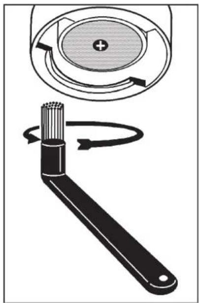
1) Clean the underpan gasket with a brush.
2) Fit the blank ring into the filter holder.
3) Pour in the filter holder the content of a sachet or a measure of detergent powder.
4) Connect the filter carrier to the group and perform a few cycles.
5) Remove the filter carrier, clean the spout with a sponge.
6) Rinse by dispensing water from each group for about 30^ .
Filter Holders
1) Pour 1 litre of cold water and a dose of detergent into a suitable receptacle.
2) Remove the filters from the filter holders.
3) Leave the filters and filter holders in the solution for at least two hours.
4) Remove any residues with a sponge and rinse in plenty of cold water.
5) Refit the filters in the filter holders, making sure that the filter fixing spring is in the correct position.
Steam and hot water dispensing pipe
Using a clean sponge, wash with hot water removing any organic residue present. Rinse carefully.
To clean the inside of the steam nozzle, follow these steps: Turn the nozzle towards the cup tray and carefully activate steam dispensing at least once.
Drip pan
Remove the drip plan and complete the cleaning with running water
Discharge tank
At the end of the working day, pour a jug of hot water into the discharge tank, removing any organic residue present.
Bodywork
Use a soft cloth and cleaning products WITHOUT ammonia or abrasives, removing any organic residue present in the work area. N.B. Do not spray liquids into the panel slots.

ATTENTION
When the machine has not been used for more than 8 hours, and in any case once a day, the internal components must be washed before use, in accordance to the following instructions:
Hot water
Dispense hot water repeatedly (using the relative command) until at least 6 liters of water have been dispensed from the 2-group machine, and 9 liters from the 3-group machine.
Supply Groups
Insert the filter carriers into the groups (without coffee) and dispense from each group for one minute.
Steam
Dispense steam from the steam pipe for about one minute, using the relative commands.
Cautions

Danger of burns
The areas marked with this sign become hot. Great care should be taken when in the vicinity of these areas.
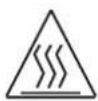
WARNING: Hot surface
ATTENTION: Surface chaude
The manufacturer disclaims all liability for damages to items or persons due to improper use or due to the coffee machine being used for reasons other than its intended use.
Never work the coffee machine with wet hands or naked feet.
Cup-warming plate
Place only coffee cups, cups and glasses to be used in conjunction with the coffee machine on the cup-warming plate.
Ensure that the coffee cups are completely drained before placing them on the cup-warming plate.
No other objects shall be placed on the cup-warming plate.

MACHINE CLOSE-DOWN
When the machine remains unattended for a long period of time (at night, during the weekly closing day or during holidays) the following operations shall be performed:
- Remove the plug or switch off the main switch.
- Close the water tap.
- Close the gas tap.
Non-compliance with these safety measures exonerates the manufacturer from all liability for malfunctions or damage to persons or items.
Danger of Burns
Do not place the hands or other parts of the body close to the coffee distribution points, or near to the steam and hot water nozzles.
Ensure that the machine is not handled by children or persons who have not been instructed in its correct use.
MAINTENANCE AND REPAIR
If the machine does not function correctly, switch it off, turn off the main switch and call the service agent.
Only qualified and authorised servicing personnel should be called.
Use only original spare parts.
Maintenance activities performed by unqualified personnel may jeopardise the safety of the machine.
If the electric cable is damaged, switch off the machine and apply to the servicing department for a replacement.

The following measures are indispensable for ensuring operational and functional safety:
- Comply with all the manufacturer's instructions.
- Ensure that specialized technicians periodically verify that the protection devices are intact and that all the safety devices function correctly (the first inspection should be made within 3 years and subsequently once yearly).
Regeneration of the Water Softener
The machine must be installed with an ionic resin water softener.
The water softener may be of different types, with different resin capacities and different periods of validity.
The resins are regenerated by adding coarse kitchen salt or salt pastilles to the water softener.
If the regeneration of the resins is not made at the due dates, calcareous deposits will form which progressively decrease the machine's efficiency until its functions are completely blocked.
The regeneration due dates and method thereof may be found in the instructions provided with the equipment.
If regeneration is performed at the due dates, the machine is maintained in ideal working conditions.
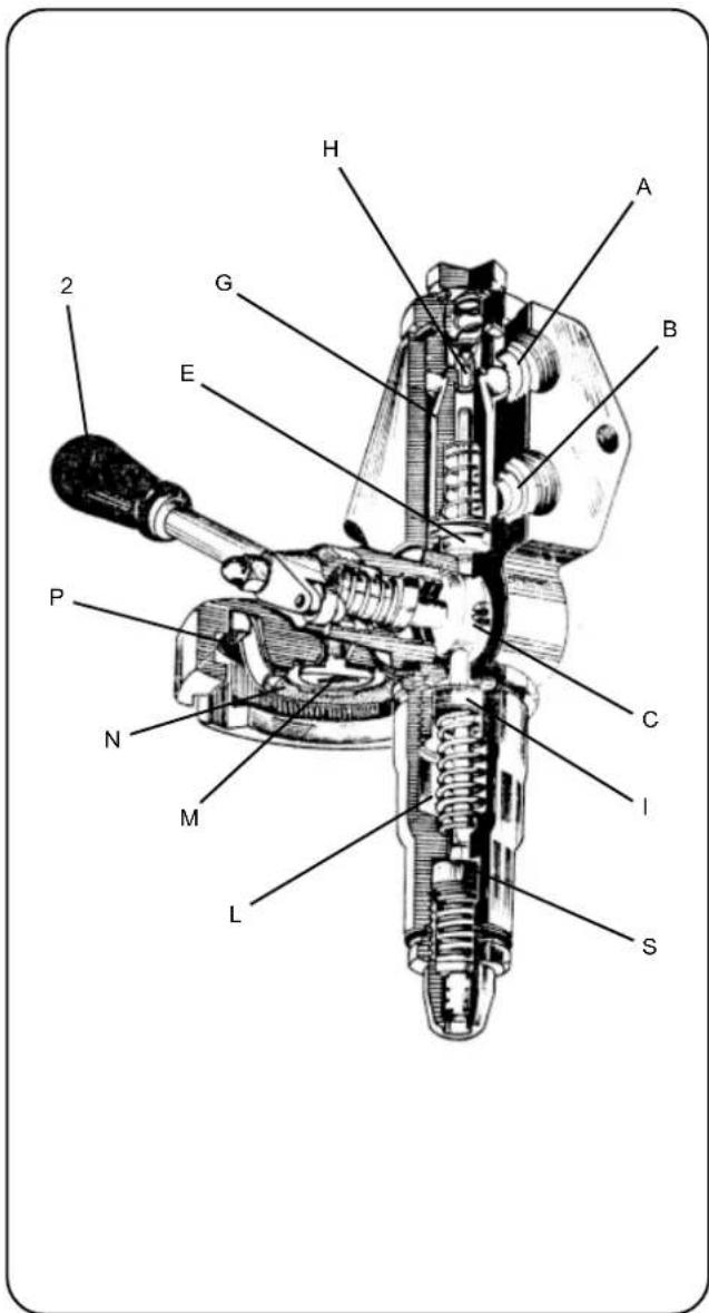
The Group
Every group is independently thermoregulated, with its own separate "THERMOSIPHON CIRCULATION".
The following devices are found on the front of the machine where the filter-holder is inserted:
-
the flow block (M)
-
the spout (N)
-
the under cup gasket (P)
On the rear are the water entry and exit perforations (A and B respectively) for the themosiphon circulation water and for the coffee.
The three group valves perform the following functions:
- The dispensing valve (E). When the group is operating this valve is open and allows the passage of water to the ground coffee. The valve is closed when the group is not operating and allows the thermosiphon circulation.
- Infusion valve (I). Determines the "cooking" of the coffee thanks to a play on the pressure.
- Drainage valve (S). This valve is closed during dispensing. It opens and drains the group at the end of the dispensing, controlled by the command lever cam wheel.
HOW THE GROUP FUNCTIONS
A. Group at rest.
- Group command lever (2) - horizontal.
- Thermosiphon circulation - the water circulates in the changer around the central head (G). (metal tube), maintaining the group thermoregulated.
- Dispensing valve (E)-Closed
- Infusion valve (I)-Kept open by the cam (C).
- Drainage valve (S)-Kept open by the cam (C).
- Filter-holder - Inserted and containing the previous coffee grounds.
- Pump- Standstill.
B. Group in operation
- Filter-holder - Inserted with freshly ground coffee.
- Group command lever (2) - Vertical.
- Pump-In operation
- Dispensing valve (E)-Kept open by the cam (C).
- Infusion valve (I)-Closed.
- Drainage valve (S)-Closed
Group command lever (2) in vertical position acts on the cam shaft which presses on the microswitch button of the pump motor.
INFUSION TIME
- The pressure in the thermosiphone circulation reaches the pump delivery head value (8 ÷ 9 bar).
- The water under pressure enters the chamber above the nozzle (H) via the 4 perforations in the central head.
- Nozzle (H) permits the passage of a small calibrated quantity of water into the group (cam chamber, dispensing chamber, ducts and space on the ground coffee) which gradually fills up until the level of pressure is reached that opens the infusion valve (I).
- At this point, the infusion chamber (L) is filled.
- While the infusion chamber is being filled, the air contained therein has contact with the ground coffee. Steam is formed in this air bubble.
- The entire group is now at infusion pressure and remains at this level until the entire infusion chamber is filled. At this point, the pressure rises to reach the pump delivery head value.
- Completion of the infusion requires about 6 seconds from the moment the group command lever (2) rises. This is the "INFUSION PERIOD".
- During this period hot water comes into contact with the ground coffee at a pressure that is not sufficient to overcome the resistance.
- The water pressure gradually increases on the ground coffee, causing its preliminary swelling and "cooking".
COFFEE DISPENSING
- At the end of the infusion period, i.e. when the water pressure on the ground coffee has reached the pump delivery head, dispensing of the "coffee cream" commences and continues until the group is halted. Dispensing of a normal coffee must last about 25 seconds.
- These times are based on the type of coffee (blend) used, its correct roast level and above all to its grinding degree.
NOTE: The closure of the group must be made quickly so that the cushion of steam that forms upon contact with the coffee grounds can contribute to an effective drainage from the group and consequently the drying of the coffee grounds.
Upon completion of the dispensing, the group drains automatically to remove the pressure and thus making it safe to remove the filter-holder.
C. DISPENSING COMPLETION
- All the group components return to the point A position.
- The opening of the infusion valves (I) and drainage valves (S) via the cam (C) empties the spaces under the dispensing valve.
Defects - Malfunctions
Direct action by the customer
Before calling service personnel, to avoid useless expense, check whether the machine problem corresponds to one of the cases listed below.
PROBLEM SOLUTIONCAUSE
| Leaking from the filter-holder rim (10). | Underpan gasket dirty with coffee. | Clean using the special brush provided. |
| Coffee dispensing time too short. Use a finer grind. | Coffee ground too coarse. Coffee too old. | Use new coffee. |
| Coffee drips out of machine. Clean. | Filter holes blocked or filter-holder (10) outlet hole dirty. Coffee ground too fine. | Use a coarser grind. |
| Loss of water under the machine. Clean. | Discharge well clogged up. Discharge pan hole blocked. | Clean. |
Defects - Malfunctions
Interventions by a specializes technician
PROBLEM COMMENTSCAUSE
| Infusion time too short Rapid dispensing. Coffee very bland, without cream. (Same defects on all groups). | Coffee grounds too course. Old coffee. | This defect is associated to other secondary symptoms which may be caused by a number of other causes as per the previous points. Do not adjust the machine until all other causes have been excluded. |
| Infusion time very short. Rapid dispensing. Coffee very bland, without cream. (Same defects on all groups). | Group nozzle widened through use. OR gasket in cone-shaped section leaks. Infusion valve remains open Filter edge broken. | The capacity of the group without filter must be 100 cm³ in 8 ÷ 10 seconds. |
| Low coffee yield. Slow dispensing. Coffee cold and bland. | Spout dirty. | If the group is operated without the filter-holder, thin, isolated jets will be dispensed instead of one central jet. |
| Fast dispensing, coffee bland. Pressure gauge pump indicates pressure greater than 9 bar. | Pump out of calibration. By-pass valve blocked. | |
| Low coffee yield. Fast dispensing. Coffee hot and bland. | Filters with perforations widened. Coarse grinding. | Coffee grounds in cup. |
| Coffee cold, bland and without cream. Normal infusion and dispensing times. | Air bubble in thermosiphon circulation. Check valve does not hold (with low pressure in system). Heat exchangers emptied. Heat exchanger defective (shows pressures higher than real values). | Move group to and fro to remove air bubble. When touching the water tube it is warm near to the machine. Pressure gauge calibrated with values that are too low. |
| Coffee cold in the morning at start of work. | Air in boiler. | See switching on instructions. |
| Dispensing slow. Coffee burnt and cold. Cream very dark, with tendency of formation of an “eye”. | Coffee grounds too fine. Low pressure in pump. Mesh filter above spout dirty. Spout partially blocked. |
Defects - Malfunctions
Interventions by a specializes technician
PROBLEM COMMENTSCAUSE
| Dispensing slow, coffee burnt. Pressure gauge pump lower than 9 bar. | Pump out of calibration. Pump with reduced capacity. | |
| Drainage tube leaks when group is at rest (defect only on one group). Coffee dispensed normally. | Dispensing valve does not hold. | If this defect is not corrected immediately, the water softener runs out long before the expiry time, with consequent scale deposit. |
| Group at rest Dispensing valve gasket fails rapidly. Water leak from the drainage tube. Coffee dispensed normally. Defect on all groups. | Expansion valve with calibration too high (above 12 bar). | If this defect is not corrected immediately, the water softener runs out long before the expiry time, with consequent scale deposit. |
| Group at rest. Continuous loss of cold water in the drainage tray. Groups do not dispense any more coffee and the pressure gauge pump shows low values. | Expansion valve remained open. | If this defect is not corrected immediately, the water softener runs out long before the expiry time, with consequent scale deposit. |
| Group in operation. Drainage tube leaks. No coffee. | Drainage valve does not hold. | |
| Group in operation. Loss of cold water in drainage tray. Coffee bland. Dispensing slow. | Expansion valve out of calibration (opens at less than 9 bar). | |
| Group leaks at cam shaft. | Leak on the two glands. | Remove the glands taking care not to mark the housings. Do not use tools made of steel or other hard materials. Before remounting, clean the shaft thoroughly, especially the grooves |
| Difficult to move the groups. | Cam profile worn. | |
| Machine does not go into pressure or reaches pressure level slowly. | No electricity. Automatic switch gone off. Resistances burned. Electric circuit to resistance interrupted. No water in boiler. | Steam taps leak: |
| Groups function normally. Pressure gauge pump does not give correct pressure reading (8 ÷ 9 bar). | Pressure gauge defective. | |
| Pump does not reach pressure level. No dispensing. | Motor does not work: - No electricity. - Capacitor burnt. - Microswitch burnt. - Motor burnt. Check valve pump open. By pass valve completely opened. | |
| Pump noisy. | Pump defective. No water in system. |
Smontaggio - Disassembly - Demontage - Abmontierung - Desmontaje - Desmontage
Disassembly of side panels
GB Unscrew screw (A) and remove the panel.
Disassembly of the cup warmer tray and glass panels
GB Loosen fasteners (B) and remove the tray.
GB Disassembly of top panels
Unscrew screws (C) and remove the panel.
Disassembly of the framework
1 - Unscrew the knobs (D) at the four corners.
2 - Remove the framework from the rear, holding it by the two lower sides and slightly rotating towards the top.
3 - Disconnect the connector of the lighted panel.
4 - Place the framework down carefully on the the 4 stud bolts towards the ground, away from the work area.
5 - Upon completion of the repair, follow the instructions from 5 to 1.
D
GB A - Screw for adjusting the boiler pressure
PRESSOSTAT
GB A - Screw for adjusting the pump pressure
BY-PASS
MACHINE EQUIPPED WITH SAFETY THERMOSTAT
[5B] In case of thermostat intervention, switch on again.
MAQUINE EQUIPÉE DE THERMOSTAT DE SURETE
SETTING THE THERMOSIPHON CIRCULATION
To set the group temperature, turn the knob as follows:
- Anticlockwise (+), for a warmer group.
- Clockwise (·) , for a colder group.
A - Reference index: standard calibration - 8
RéGLAGE DU CHAUFFAGE A THERMOSIPHON
10 = Automatic level board
17 = Level probe
19 = Automatic level solenoid valve
26 = Pump motor
27 = Pump capacitor
30 = Pressure switch
31 = Boiler heating element
33 = Boiler thermal cut-out
45 = Pump motor switch
46 = Led electronic board
47 = Led switch
59 = Pump fuses *
Items marked -* - are fitted in some product configurations only.
F LEGENDE
1 = Pump pressure gauge
2 = Pump filter
3 = Pump
4 = Pump pressure regulator
5 = Non return valve (heat exch.)
6 = Expansion valve
9 = Boiler
10 = Safety valve
11 =Vacuum release valve
12 = Coffee dispenser group
15 = Boiler non return
18 = Hot water tap
19 = Water filling manual valve
20 = Pin-tap for solenoid valve 21
21 = Automatic filling solenoid valves
22 = Automatic filling neck
23 = Steam tap
26 = Pressure switch
27 = Level indicator
29 = Boiler pressure gauge
31 = Heat exchangers
32 = Automatic level probe
36 = Drain valve
37 = Infusion valve
38 = Dispensing valve
39 = Infusion nozzle
40 = Nozzle filter
41 = Thermosiphon setup valve
F LEGENDE
Copyright by FAEMA S.p.A., Milano
FAEMA reserves the right to make changes to the machines in accordance with the needs of individual countries and on the basis of technological progresses.
This publication may not, either in whole or in part, be used, copied or published without the written authorisation of FAEMA S.p.A.
Copyright by FAEMA S.p.A., Milan, Italy
All rights reserved

FAEMA S.p.A.
Via Manzoni, 17
20082 Binasco
(MI) Italy
Tel: +39-2-90.04.81
Fax: +39-2-90.54.818
www.faema.it
Copyright by FAEMA S.p.A., Milano
Copyright by FAEMA S.p.A., Milano
Copyright by FAEMA S.p.A., Milan
Todoosdedechosestanreservados

FAEMA S.p.A
Via Manzoni, 17
20082 Binasco
(MI) Italy
Tel: +39-2-90.04.81
Fax: +39-2-90.54.818
www.faema.it
Copyright by FAEMA S.p.A., Milano
FAEMA and the "SERVICE LINE"
The FAEMA Company's client service, the aim of which is to assure top coffee-machine performance for its clients at all times, also makes available its ECO LINE, a series of specific cleaning products expressly designed for this purpose.
ECO LINE - Cleaning products
A) For cappuccino makers in liquid form 4991-134458;
B) For dispensers, filter-holders, coffee cups in powder form 4991-134682;
C) For dispensers, filter-holders, coffee cups in small envelopes 4991-134681;
D) For superautomatic-machine dispensers in tablet form 4991-134683.
Order directly from your local distributor and refer to the particular item you require by its number, as shown above.

FAEMA et la "SERVICE LINE"

- D
- F LEGENDE
- ATTENZIONE
- ATTENTION
- Installazione - Installation - Installation - Installation - Instalación - Instalación
- INDICATIONS POUR L'INSTALLATION
- INDICACOsParaAINSTALACAO
- F
- CONNECTION HYDRAULIQUE
- F BRANCHEMENT ELECTRIQUE
- Installazione - Installation - Installation - Installation - Instalacion - Instalacao
- D STROMANSCHLUSS
- COLLEGAMENTO EQUIPOTENZIALE
- F CONNEXION EQUIPOTENTIELLE
- 1) HYDRAULIC CONNECTION
- 2) OPERATION
- HOT WATER:
- STEAM:
- Certification for materials in contact with food used in FAEMA products
- CE Declaration of conformity
- Daily Switch-On
- Heating phase
- Delivery of the coffee
- Other hot beverages
- Steam dispensing
- Dispensing hot water
- Water level control of boiler
- Filling the boiler with water using the manual service tap
- Cleaning and maintenance
- Cleaning the dispenser units
- Filter Holders
- Steam and hot water dispensing pipe
- Drip pan
- Discharge tank
- Bodywork
- Hot water
- Supply Groups
- Steam
- Cautions
- Danger of burns
- WARNING: Hot surface
- Cup-warming plate
- MACHINE CLOSE-DOWN
- MAINTENANCE AND REPAIR
- Regeneration of the Water Softener
- The Group
- HOW THE GROUP FUNCTIONS
- Group at rest.
- Group in operation
- INFUSION TIME
- COFFEE DISPENSING
- DISPENSING COMPLETION
- Defects - Malfunctions
- Direct action by the customer
- Smontaggio - Disassembly - Demontage - Abmontierung - Desmontaje - Desmontage
- Disassembly of the framework
- PRESSOSTAT
- BY-PASS
- MACHINE EQUIPPED WITH SAFETY THERMOSTAT
- MAQUINE EQUIPÉE DE THERMOSTAT DE SURETE
- SETTING THE THERMOSIPHON CIRCULATION
- RéGLAGE DU CHAUFFAGE A THERMOSIPHON
- FAEMA and the "SERVICE LINE"
- FAEMA et la "SERVICE LINE"
Brand : Faema
Model : E61 3 GR
Category : Coffee machine