HB300 - Boiler ACV - Free user manual and instructions
Find the device manual for free HB300 ACV in PDF.
| Product type | Boiler / Heat pump water heater |
| Model | ACV HB300 (HB300C with solar exchanger) |
| Nominal volume | 300 L (HB300), 287 L (HB300C) |
| Dimensions (diameter x height x depth) | 661 x 1930 x 720 mm |
| Weight | 124 kg (HB300), 141 kg (HB300C) |
| Electrical supply | 230 V ~ / 50 Hz |
| Maximum absorbed power | 1200 W (heat pump) / 1800 W (electric heating element) |
| Maximum current | 16 A |
| Nominal service pressure | 0.6 MPa (6 bar) |
| Maximum safety valve pressure | 0.7 MPa (7 bar) |
| Maximum water temperature | 60 °C |
| Operating ambient temperature range | -7 °C to +43 °C (heat pump) / -30 °C to +43 °C (electric heating element) |
| Nominal COP | ≥ 3.5 (at 15/10-45 °C) |
| Sound level | 48 dB(A) |
| Air flow rate | ≈ 500 m³/h |
| Water connection | G 3/4 |
| Refrigerant | R134a, 1100 g, GWP 1300 |
| Protection class | IPX4 |
| Thermal insulation | CFC-free PUR foam, 50 mm |
| Tank material | Enameled steel |
| Corrosion protection | Enamel + active anode |
| Heating modes | Economy (heat pump), Hybrid, Electric only |
| Special functions | Timer, child lock, temperature display, error codes |
| Recommended maintenance | Clean the air filter every month; descaling and anode check every 2 years |
Frequently Asked Questions - HB300 ACV
User questions about HB300 ACV
0 question about this device. Answer the ones you know or ask your own.
Ask a new question about this device
Download the instructions for your Boiler in PDF format for free! Find your manual HB300 - ACV and take your electronic device back in hand. On this page are published all the documents necessary for the use of your device. HB300 by ACV.
USER MANUAL HB300 ACV
| 2 EN 2 | ||
| Contents | ||
| duction 4. | ||
| general information 4. | ||
| Application area 4. | ||
| Instructions and technical norms 4. | ||
| Explanation of applied symbols 4. | ||
| Package content 5. | ||
| Transport and handling 5. | ||
| technical features 5. | ||
| Operation principle 5. | ||
| Operation explanation | 6. | |
| Water heating methods | 7. | |
| Explanation of water heating operation | 7. | |
| Mode selection | 7. | |
| Construction features | 8. | |
| Name of parts | 8. | |
| Overall dimensions 9. | ||
| Control circuit diagram of heat pump water heater | 9. | |
| Summary table of technical data | 10. | |
| seful recommendations (Usage and maintenance instructions for users) | 11. | |
| First installation 11. | ||
| Instructions and warranty | 11. | |
| Recommendations | 11. | |
| Safety precautions | 12. | |
| usage instructions 13. | ||
| Control panel explanation | 13. | |
| Display explanation | 13. | |
| Operation | 14. | |
| Operation procedure | 14. | |
| Error code explanation | 21. | |
| maintenance | 22. | |
| Planned preventive maintenance to be performed by the user | 22. | |
| Routine check of heat pump water heater | 22. | |
| Technical support | 22. | |
| Disposal of water heater | 22. | |
| 6. | Useful recommendations ( Technical information for installing technicians) 23. | |
| 6.1. | Qualification of installing technicians 23. | |
| 6.2. | Usage of installation, usage and maintenance manual 23. | |
| 6.3. | Check of heat pump water heater 23. | |
| 6.4. | Safety precautions 23. | |
| 7. | Putting into operation 25. | |
| 7.1. | Placement of water heater 25. | |
| 7.2. | Duct connection ways 28. | |
| 7.3. | Pipeline connection 32. | |
| 7.4. | Electric connection 33. | |
| 7.5. | First start up 34. | |
| 8. | Maintenance instructions (For personnel authorized to perform maintenance) | 35. |
| 8.1. | Appliance discharge 35. | |
| 8.2. | Storing and combined safety valve 35. | |
| 8.3. | Active anode 35. | |
| 8.4. | Scale removal 35. | |
| 8.5. | Prevention of frost damages 35. | |
| 8.6. | In case of indirect heating 35. | |
| 8.7. | Air filter 36. | |
| 8.8. | Shutoffs not caused by errors 36. | |
| 8.9. | Errors and solutions 36. | |
| 8.10. | Self-protective mechanisms of the appliance 36 | |
INTRODUCTION
This manual is for end users of heat pump water heater of types HB300 and HB300C (hereinafter referred to as HB300(C) if both types are concerned) and building engineers performing installation. The manual is an integrated and indispensable part of the appliance. Therefore, the user should carefully keep the manual and hand it over to the new owners or users of the appliance.
In order to ensure adequate and safe usage of the appliance, both the installation technicians and the users of the appliance should read manual instructions and safety precautions carefully as they contain important information on appliance safety, putting into operation, usage and maintenance for users and installation technicians, as well.
1. GENERAL INFORMATION
1.1. Application area
The appliance produces domestic hot water or hot water of similar usage at temperature under the boiling point. For this aim, the appliance must be hydraulically connected to the domestic water pipeline. Electric current is also required for the operation of the appliance. The usage of air ducts is optional and it will be described later in details.
It is forbidden to use the appliance for purposes other than the pre-defined ones. Any other usage of the appliance is considered to be improper and therefore forbidden. The appliance must not be used especially in environments exposed to industrial cycles and / or corrosive or explosive materials.
The manufacturer and distributor shall take no responsibility for damages raised by inefficient installation, improper or wrong usage, rationally not foreseen usage or incomplete or careless compliance of manual instructions.
1.2. Instructions and technical norms
Persons with reduced physical, perceptive or mental abilities (including children) or persons without complete knowledge and experience on the appliance are not permitted to use the appliance, except for the person responsible for their safety ensures supervision or adequate information on the operation of the appliance for them. Supervision of children is required to avoid that they play with the appliance.
The manufacturer is responsible for ensuring that the appliance complies with all construction guidelines, regulations and requirements effective at the time of the first commercial marketing of the product. The constructor, user and installation technician are exclusively responsible for knowledge and compliance of regulations on the construction, installation, operation and maintenance of the appliance in their competency areas. References on laws, requirements of technical descriptions used in this manual are for information only. Newly implemented laws or modifications of efficient laws shall not be legally binding for the manufacturer against third persons in any way.
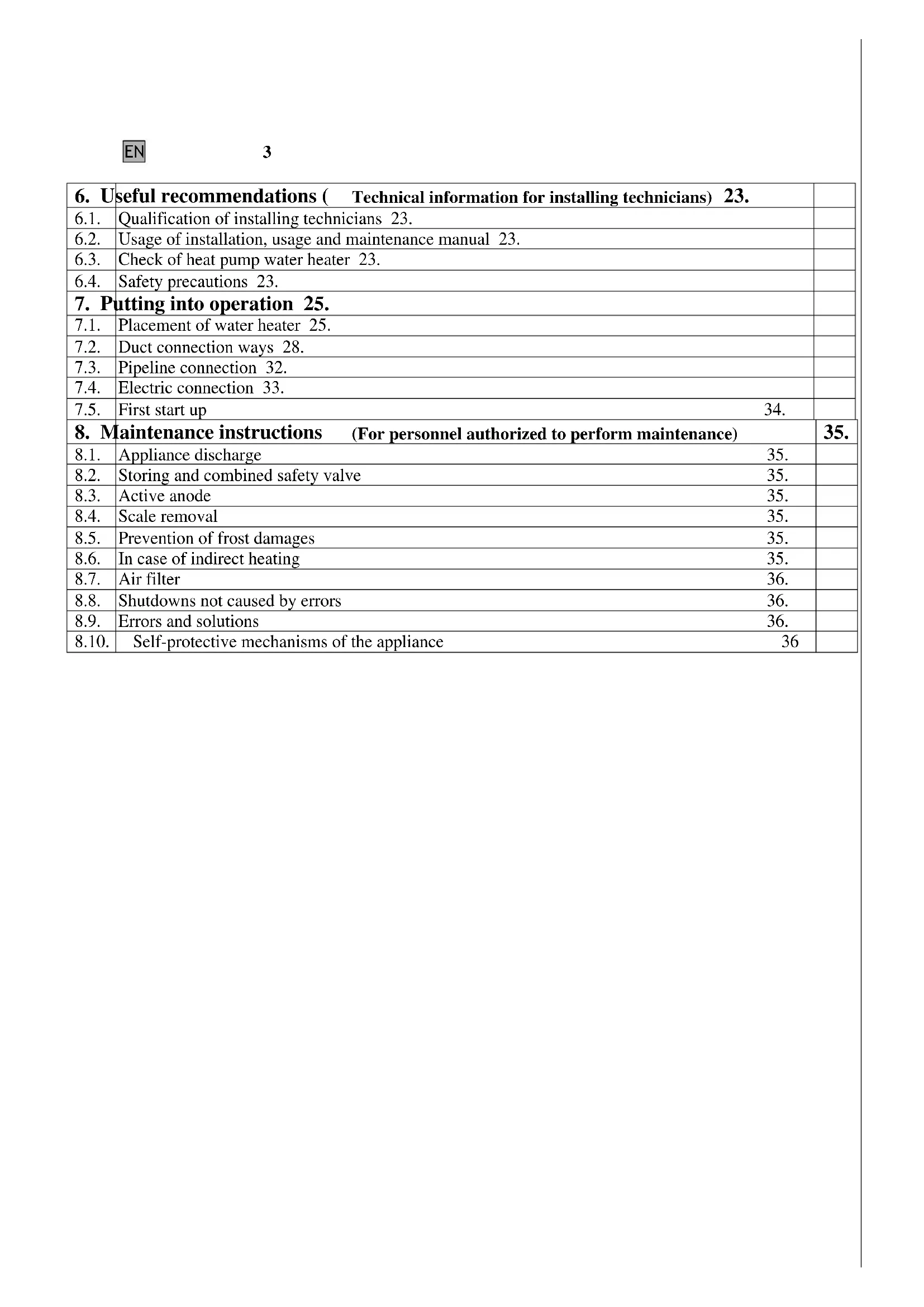
1.3. Explanation of applied symbols
Concerning putting into operation of appliance and operation safety of the appliance, the following symbols are used in order to underline the importance of warnings of danger:
Failure to observe a warning may result in serious injury or in death, in some cases.
Failure to observe a warning may result in serious injury or damage in the building, in the plants or in the animals.
Compulsory compliance with general and specific safety instructions of the product.
Parts or points written after the expression "WARNING!" and/or written in bold type contain important information or recommendation and it is indispensable to take them into consideration and to comply with them.
1.4. Package content
The appliance is transported in carton box with internal protective elements.
The package contains the following:
Installation, usage and maintenance manual 1 item
Y filter Rp3/4 1 item
Flexible conduit to discharge condensate water 1 item
Feet fixing 3 items
Drill frame 1 item
Wire installation rubber 1 item
1.5. Transport and handling
During product delivery, please check that there is no visible damage on the external part of packaging. If the product seems to be damaged, please turn to the delivery company with your complaint in no delay.
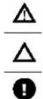
Similar to all equipment containing a compressor, the heat pump must be stored and transported only in a standing position (see Figure 1.5.-1.)
WARNING!
The appliance must be transported, handled or stored in a vertical position and it must not be inclined more than 45^ (Figure 1.5.-2.). This appliance is very heavy, it needs to be carried by 2 or more persons, otherwise it might cause personal injury or appliance damage. If during any of the operations above, the placement of the appliance needs to be different from the recommended position, before the first start up of the appliance, please wait at least 3 hours starting from the time when the appliance has been put into the proper vertical position and / or into operation. This way, it is ensured that the lubricating oil working within the cooling circuit is placed properly and compressor damage is avoided.
The packaged appliance can be handled by hand or by lift truck - please follow the instructions printed on the carton box.
It is recommended to keep the appliance in the original packaging until it is installed on the selected place, if possible, especially when construction work is performed on the site.
During the removal of the package, please check that the appliance is intact and all necessary parts are placed in the package. In case of any deficiency or missing parts, please notify the contracted distributor within the deadline defined by law.
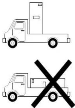
Figure 1.5.-1.
Figure 1.5.-2.
WARNING!
Due to potential danger, please keep packaging material (clips, plastic sacks, polystyrene foam) away from children.
During handling or transportation of the appliance after its first start up, please keep warnings on maximum inclination angle described above and ensure that all water has been discharged from the tank. If the original packaging no longer exists, please provide protection to the appliance and its parts similar to the original packaging.
2. TECHNICAL FEATURES
2.1. Operation principle
HB300(C) heat pump water heater is seemingly similar to traditional electric hot water tanks. During its normal operation cycle, HB300(C) connected to household pipeline and electrical power system does not use as much electric power for direct heating of water as the traditional electric hot water tank does, but rather, it uses energy in a more rational and efficient way, reaching the same result with an energy use of less than 70% as compared to the traditional electric hot water tank.
Heat pump is named by the fact that it is able to transfer heat from a heat source of lower temperature to a heat source of higher temperature, which means it turns natural flow of heat, which is transferred from a heat
source of higher temperature to a heat source of lower temperature. The application of the heat pump brings the benefit that it is able to transfer more energy (in form of heat) than the energy it takes for its operation (in form
EN
6
of electric power). This way, heat pump is able to extract energy from heat sources existing in its environment without "expenditure", depending on the type and availability of the heat sources.
HB300(C) heat pump water heater extracts heat from stuffy internal air to be refreshed, thus it adds to the efficiency increase of water heating. It is possible to select among several different configurations to use environmental air, which provides multilateral application of the appliance besides different operational conditions.
HB300(C) heat pump water heater has been planned and manufactured pursuant to specifications on the energy performance of buildings. The appliance ensures more rational energy use and leads to savings in the operational costs. As opposed to other alternative systems used to produce sanitary hot water, heat extraction from free energy sources definitely reduces environmental effects of emissions into the atmosphere.
2.2. Operation explanation
According to the facts mentioned above, the "energetic capacity" of heat pump is based on heat transfer through heat extraction from free source (in this case, it is the environmental air) with lower temperature than the material to be heated (in this case, it is the water in the tank of the water heater). Electric power is required for the operation of the compressor (that leads to change of state of matter of the cooling fluid within the cooling circuit), thus for the transfer of heat energy. Cooling fluid passes along a closed hydraulic circuit where the fluid changes into liquid or gaseous state of matter in connection with its temperature and pressure. The main elements of the hydraulic circuit (Figure 2.2-1) are the following:
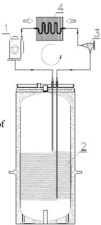
Figure 2.2.-1.
1 - compressor, which ensures cycle running through increasing the pressure and the temperature of the cooling fluid (which has a gaseous state of matter in this cycle).
2 - first heat exchanger located in the water tank of the water heater: heat exchange between the cooling fluid and the sanitary water to be heated up is produced on its surface. As in this phase, the state of matter of the warm cooling fluid changes and it condenses into liquid while transferring its heat to the water, this heat exchanger is defined as condenser.
3 - expansion valve: it is an equipment through which the cooling fluid passes just when its pressure and temperature are reducing, following the expansion of the liquid perceivably as a result of pipe cross-sectional area increase above the valve.
4 - second heat exchanger located in the upper part of the water heater, which surface has been increased by fins. The second heat exchanger performs heat exchange between the cooling fluid and the environmental air drifted artificially by either the free source or by a special fan in a proper way. As in this phase, the cooling fluid evaporates and extracts heat from the environmental air, this heat exchanger is defined as evaporator.
As heat energy is able to flow from a higher temperature level to a lower temperature level exclusively, the temperature of the cooling agent located in the evaporator (4) has to be lower than the environmental air acting as free source, in the same time, in order to transfer heat, the cooling agent located in the condenser (2) has to possess a temperature higher than the temperature of the water to be heated in the tank.
The temperature difference within the heat pump circuit is produced by the compressor (1) located between the evaporator (4) and the condenser (2) and by the expansion valve (3), due to physical features of the cooling fluid.
The efficiency of the heat pump circuit can be measured by the coefficient of performance (COP). COP is the ration of incoming energy into the appliance (in this case, it is the heat transferred to the water to be heated) to the electric power used (by the compressor and the supporting equipment of the appliance). COP may change depending from the type of the heat pump and the related operational circumstances. A value of 3 for COP means, for example that the heat pump transfers 3kWh to the material to
be heated after 1kWh electric power used, from which 2kWh is extracted from the free source. The rated COP values of HB300(C) heat pump water heater are listed in table 2.10.1 containing technical data.
The temperatures of typical heat pump cycles, in connection with features of the cooling fluid and the free source ensure heating of sanitary water located in the aluminium pipe heat exchanger placed outside of
EN
7
HB300(C) heat pump water heater up to a temperature of max. 60^ , besides normal usage conditions. As HB300(C) heat pump water heater has been equipped with a supplementary pipe radiator that provides further options: quicker obtaining of operation with full capacity through combination of heat pump mode and pipe radiator mode up to a temperature of max. 60^ that may be used after running of antibacterial protective cycles. In order to ensure rational energy use during the operation of the hot water tank, visual indicators call the attention of the user on the fact that the appliance is not operated in the most efficient way if the pipe radiator is active.
2.3. Water heating methods
The appliance (in case of HB300C type) integrates heating elements that contain a heat pump, an electric pipe radiator and a heat exchange pipe coil. Heating elements do not operate all the three in the same time. Hot water tanks of HB300C type can be operated from several different energy sources: indirectly from solar energy, or gas-based, coal-based or other based energy carriers, furthermore, auxiliary electric heating provided by appliances of HB300(C) type is controlled by the heat pump unit.
This appliance possesses two temperature-sensors that are placed in the upper flare located in the closing cover and in the lower flare. The sensor placed in the upper flare measures upper temperature and this number is displayed by the Water temp indicator, while the sensor placed in the lower flare monitors the lower temperature, which serves as input data for switch on/ off, but this is not displayed at all.
1.) Economy Mode:
In this mode, it is the heat pump that is working, not the electric heater as a result of pre-set water temperature.
(The water outlet temperature is between 38 60^ , the operation environment temperature is between -7 43^ )
2.) Hybrid Mode:
In this mode, the equipment is sharing its operation capabilities between electric heating and heat pump, based on the temperature of the water tank.
(The water outlet temperature is between 38 60^ , the operation environment temperature is between -30 - 43^ )
3.) E-heater Mode:
In this mode, the motors of the compressor and the fan are not working, only the electric heater is working. This time, only water located in the upper part of the tank is heated, which means approximately 100 l.
(The water outlet temperature is between 38 60^ , the operation environment temperature is between -30 43^ )
a) Defreezing through water heating
In case of Economy Mode and Hybrid Mode, if the evaporating steam freezes in cold environment, the appliance defreezes it automatically, to ensure efficient performance (3~10 min).
b) External environmental temperature
The operation temperature of the appliance should be within the interval -30 43^ and the operation temperatures of the modes are described below in details.
2.4. Explanation of water heating operation
1) Economy Mode: -7 43^
This mode is recommended when the external environmental temperature is between -7 43^ . If the external environmental temperature falls under the temperature of -7^ , energy efficiency becomes low, evidently, thus it is recommended to use E-heating mode under these circumstances.
2) Hybrid Mode: -30 43^ °C
3) E-heater Mode: -30~43° °C
In each case, only water located in the upper part of the tank is heated, which means approximately 100
2.5 Mode selection
As different modes have been developed to serve different needs, it is recommended to consider the following: .
Economy Mode:-7~43°C,
In case of continuous hot water need under 300L (60^)
- Hybrid Mode: -30 43^
In case of continuous hot water need between 300L (60^)
E--heater Mode: -30 43^,
In case of continuous hot water need under 100L (60^)

8
2.6 Construction features
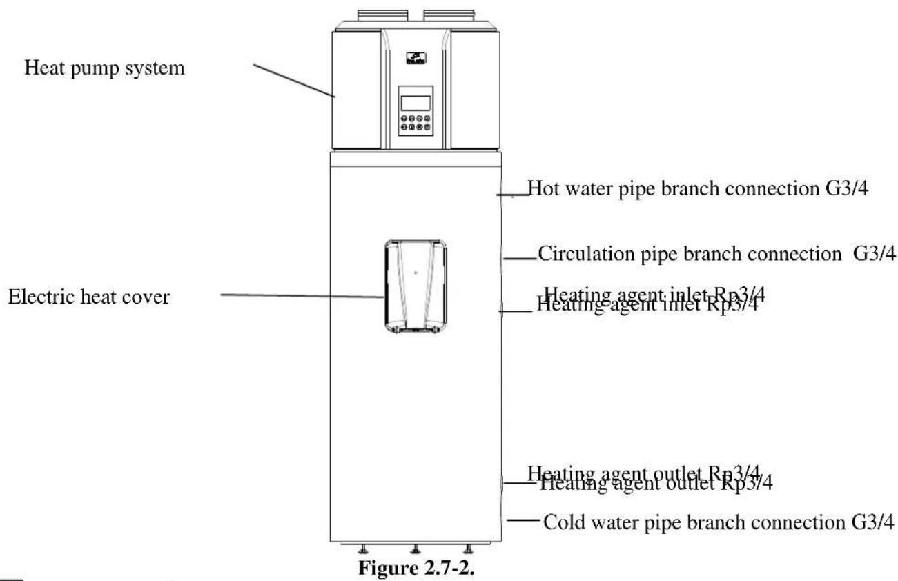
HB300(C) heat pump water heater is basically composed of an upper part (Figure 2.7.-1.) containing heat pump equipment and a lower part (Figure 2.7.-2.) containing the storage tank. The storage tank of the sanitary hot water- having a volume of - is covered by an enamel coating internally and by a thick polyurethane insulation layer having large efficiency externally, and the latter is covered by plastic surface of the appliance. The pipe radiator, controlling indicator anode electrics and magnesium indicator anode located on the closing cover are placed on a horizontal axle common with the closing cover.
The condensate water discharge pipe branch is located in the rear part of the circle-shaped tray above. The control panel equipped with display is located in the front part. All the other parts of the heat pump circuit are located above the storage tank according to a precisely planned order, which produces optimal operation, reduced vibration and noise emission.
The following parts are placed under an easily accessible and adequately insulated plastic coverage: compressor, thermostatic expansion valve, evaporator, fan ensuring adequate air flow and all the other parts displayed on Figure 2.7.-1.
2.7. Name of parts
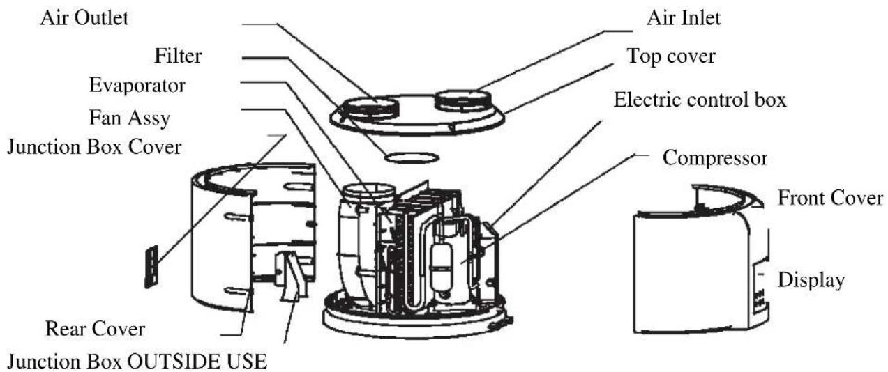
Figure 2.7.-1.

9
REMARK
All the figures in this manual are for explanatory purpose only. They may be slightly different from the heat pump water heater You have purchased (depending on product model). The actual shape shall prevail.
2.8. Overall dimensions
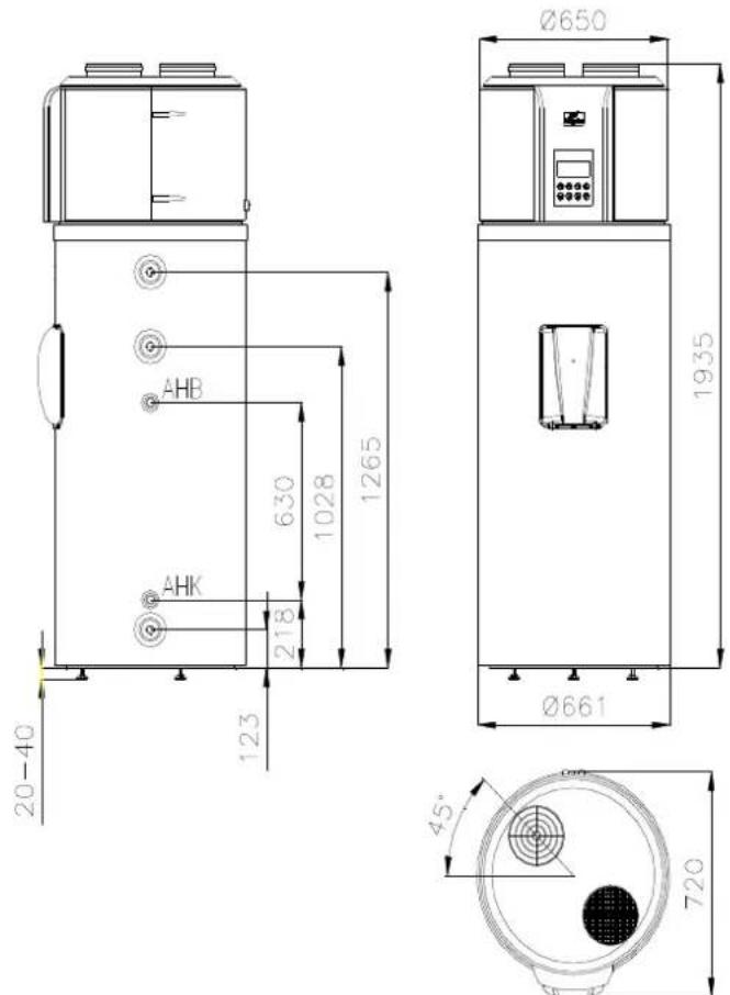
Figure 2.8-1.
2.9. Control circuit diagram of heat pump water heater
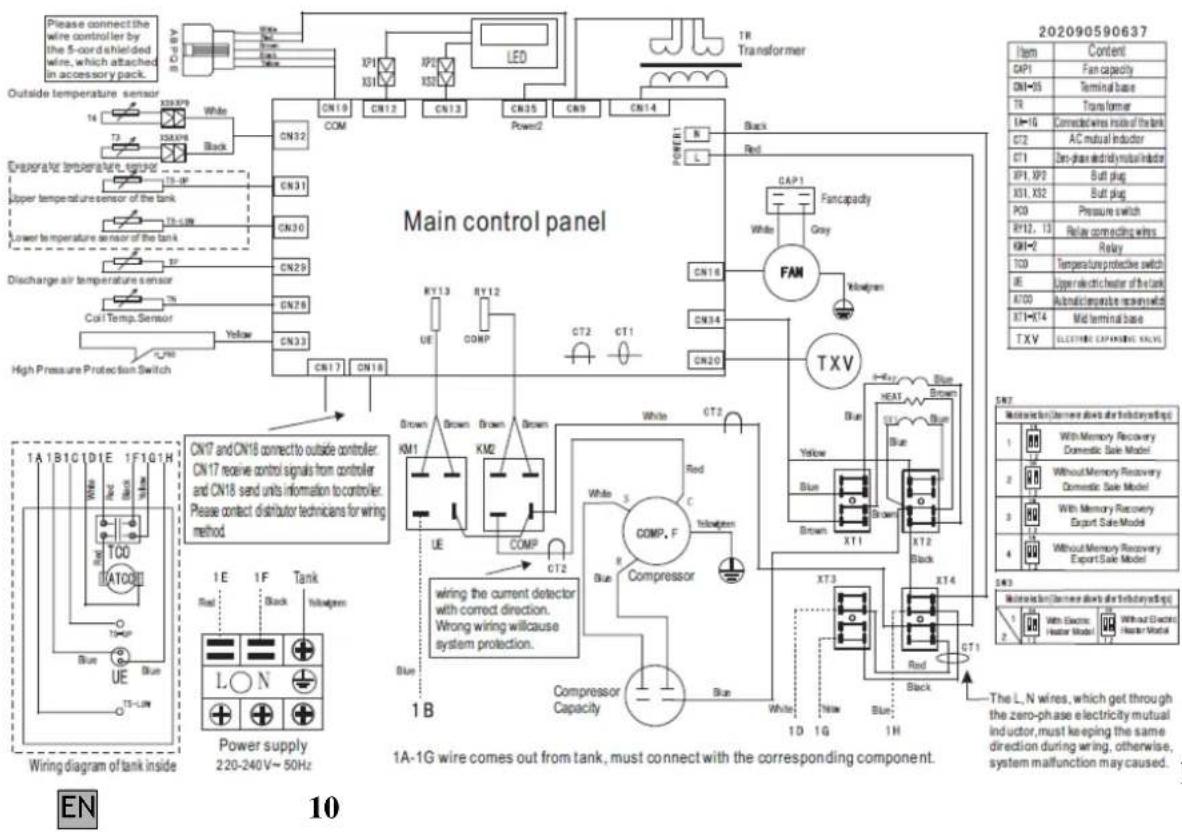
Figure 2.9-1
2.10. Summary table of technical data
QUALITY CERTIFICATION LABEL-TECHNICAL DATA
| Type | HB300 HB300C | |
| Sizes: diameter/height/depth Ø661/1930/720 | ||
| Water pipeline connection G3/4 | ||
| Circulation pipe branch connection G3/4 | ||
| Rated volume 300 I 287 | ||
| Rated operation pressure 0,6 MPa | ||
| Safety valve max. opening pressure 0,7 MPa | ||
| Largest water supply pressure 0,525 MPa | ||
| Smallest required network pressure 0,01 MPa | ||
| Standby energy use at 60°C 2500 Wh/24h | ||
| Weight | 124 kg | 141 kg |
| Pipe coal | ||
| Pipe coal connection | Rp3/4 | |
| Pipe coal heatable volume | 287 l | |
| Pipe coal surface | - | \( 1,5\ m^2 \) |
| Pipe coal flow resistance | 130 mbar | |
| Top performance | 510 l/the first 10 minutes | |
| Durable performance | 1100 l/h | |
| Durable performance | 45 kW | |
| Heat pump | ||
| Type | air (indoor) | |
| Air duct connection (inlet/outlet) | Ø190 mm | |
| Condenser | safety heat exchanger | |
| GWP / Cooling agent / quantity | 1300 / R134a / 1100 g | |
| Max. Power Consumption | 1200W | |
| Average Power Consumption | 850W | |
| Air flow | ~500m³/h | |
| Reachable static pressure | 80 Pa | |
| External static pressure range where the appliance has been examined | 1013 – 1050 hPa | |
| Max. suction side pressure | 1,0 MPa | |
| Max. blow side pressure | 2,5 MPa | |
| Minimum space required for operation (in case of operation without air duct 20 m | |
| Operation temperature range -7 - +43 | °C |
| Max. water temperature 60 | °C |
| COP 15/10-45°C ≥3,5 | |
| Noise level 48 dB(A) | |
| Type of outlet air Air support flowing vertically upward | |
| Electric heating | |
| Heatable volume 100 l | |
| Voltage/frequency L/N/PE 230V~ / 50Hz | |
| Fuse 5A/250V~(T) | |
| Rated heating performance 1800W | |
| Largest electric power consumption 16 A | |
| Heating time 3,5 h | |
| Max. water temperature 60 | °C |
| Min. Water temperature 10 | °C |
| Others | |
| Heat insulation/thickness | Freon free PUR insulation / 50 mm |
| Tank Enamelled steel sheet | |
| Pipe coal | Enamelled steel pipe |
| Corrosion protection | Enamel + active anode |
| Active anode maintenance | Anode consumption display |
| Built-in controller | Electric heating and temperature controlling device |
EN
11
Table 2.10.-1.
| Electric wiring | Fixed |
| Protection degree | IPX4 |
| Touch protection to be applied | Touch protection class I. |
| It can be connected to electric system supplied with protective earthing as defined in Hungarian Standard MSZ 2364. | |
| Regulations on the product: | (Hungarian Standards) MSZ EN 60335-1 MSZ EN 60335-2-21 MSZ EN 14511-3 |
| Storage and transportation requirements | (Hungarian Standards) MSZ IEC 721-3-1 IE12 MSZ IEC 721-3-2 IE22 |
| Quality certification | CE indication |
| Quality | Ist class |
HAJDU Hajdusagi Industrial Closed Company Limited by Shares (HAJDU Hajdusagi Iparmuek Zrt) as manufacturing company hereby certifies that the appliance comply with the technical features described in the quality certification label.
USAGE AND MAINTENANCE INSTRUCTIONS FOR THE USER
Thank you very much for purchasing our product.
We hope that the appliance fulfils all expectations and provides the best possible service for You continuously, besides maximum energy saving.
Before using your appliance, please, read this manual carefully and keep it for future reference.
3. USEFUL RECOMMENDATIONS
3.1. First installation
WARNING!
Putting into operation and first start up of the appliance can only be performed by a technician according to all related effective regulations or legal requirements or any requirements defined by local authorities and public health organizations.
If the water heater to be installed does not simply replace an existing appliance but it represents part of renovation of an existing hydraulic system or a new hydraulic system, the company installing the water heater shall be obliged to issue a compliance statement for the
buyer, certifying compliance with all effective regulations and specifications after finishing installation of the appliance. In both cases, the company performing installation has to execute safety and operation checks on the entire system.
Before starting up the hot water tank, please check that the installing technician has performed all required operations of installation. Please ensure that You have properly understood the information provided by the installing technician on how to use the hot water tank and how to perform the operations on the appliance.
3.2. Instructions and warranty
The manual is an integrated and indispensable part of the appliance. Do not remove the data label on the appliance for any reason as these data may be required for any possible future reparations.
Please, read the warranty document related to the appliance carefully. This document contains specifications regulating warranty.
3.3. Recommendations
In case of failure and/or defective operation, please do not try to search the error and correct it, rather, switch the appliance off and turn to our service. In case of reparation, original spare parts are to be used exclusively, and any type of reparation work can only be performed by a qualified technician. Failure to consider these recommendations may endanger the safety of the appliance and it invalidates the responsibility undertaken by the manufacturer.
If the appliance is not used for a longer period, it is recommended to perform the following:
-
disconnect the appliance from the electric power system in a way that if there is a switch between the appliance and the power system, then turn the switch into "OFF" position.
-
close all the faucets of the water pipeline of the household
EN
12
WARNING!
It is recommended to discharge water from the appliance if it is not used and it is placed in a location that is exposed to frost. This operation can only be performed by a qualified technician. WARNING!
Running hot water with temperature above 50^ may cause serious burn marks. The maximum water temperature displayed on the indicator is 60^ , which value can be actually higher than that in case of defective operation. Children, disabled persons and elder persons are highly exposed to burn marks. It is therefore recommended to connect a thermostatic mixing valve to the water outlet pipe of the appliance.
3.4. Safety precautions
The explanation of the symbols used in the table below is described in details in point 1.3, chapter GENERAL INFORMATION.
| Warning Danger | |||
| 1. | Do not perform any operation that causes removal of the appliance from its operational place. | Danger of electric shock caused by touching the parts under power. | Δ |
| Flood caused by water leaking from disconnected pipes. | Δ | ||
| 2. | Do not leave any object on the appliance. | Personal injuries caused by falling objects due to vibration effect. | Δ |
| Damage of the appliance or objects under the appliance caused by falling objects due to vibration effect. | Δ | ||
| 3. | Do not climb onto the appliance. | Personal injuries caused by fall over of the appliance. | Δ |
| Damage of the appliance or objects under the appliance caused by fall over of the appliance from its mounted place. | Δ | ||
| 4. | Do not perform any operation that requires opening the appliance. | Electric shock caused by touching the parts under power. Burn marks caused by overheated parts and injuries caused by sharp edges or salients. | Δ |
| 5. | Do not cause damage in the feeder wire. | Electric shock caused by uninsulated wires under power. | Δ |
| 6. | During cleaning the appliance, do not step on chair, table, ladder or any other instable support. | Personal injury caused by fall down or by accidental closing of the standing ladder. | Δ |
| 7. | Before cleaning, the appliance always has to be switched off and the external switch has to be turned into “OFF” position. | Electric shock caused by touching the parts under power. | Δ |
| 8. | Do not use the appliance for purposes other than the normal household operation. | Damage of the appliance caused by operational overcharge. Damages caused by improper usage of the objects. | Δ |
| 9. | Neither children, nor persons without professional experience can operate the appliance. | Damage of the appliance caused by improper usage. | Δ |
| 10. | Do not use pesticides, solvents or aggressive cleaning supplies to clean the appliance. | Damages of plastic parts. | Δ |

13
4. USAGE INSTRUCTIONS

WARNING!
Please follow the general warnings and safety precautions listed in the previous chapter and please comply with them strictly.
WARNING!
Any operations other than the ones listed here should be performed by qualified technician.
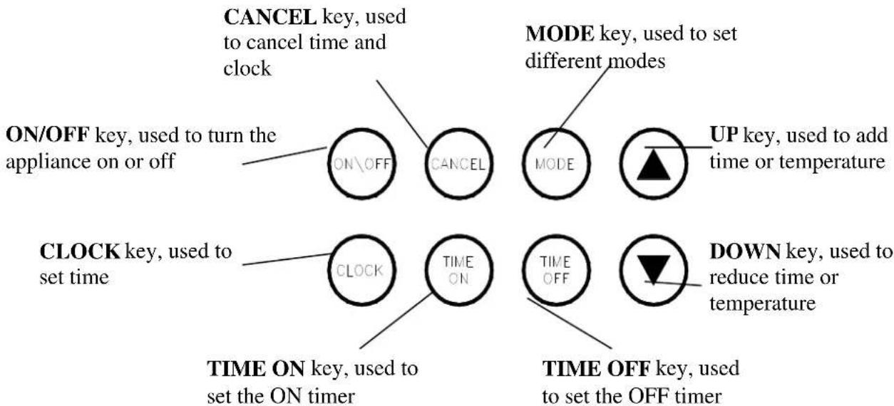
4.1. Control panel explanation
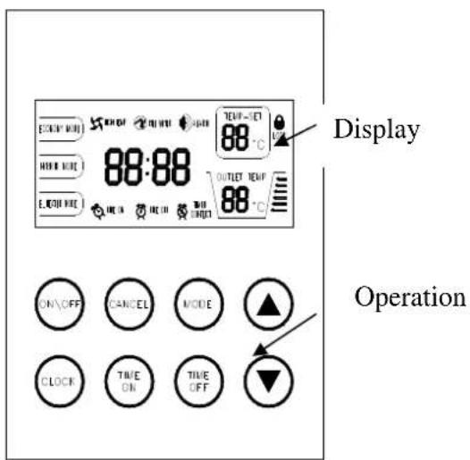
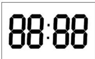
4.2. Display explanation
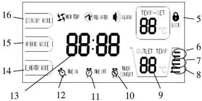
| 1 | HIGH TEMP indicator: When the setting temperature exceeds 50 °C, it lights up to remind you that the outlet temperature is too high for direct spray. |
| 2 | FILL WATER indicator: When the power supply is turned on, it lights up to remind you to re-affuse water. |
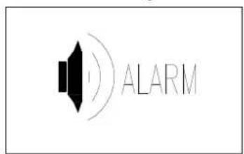
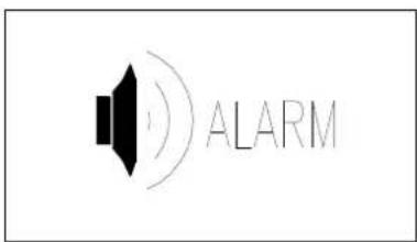
| 3 | ALARM indicator: it flashes continuously at malfunctioning or protection time. . |
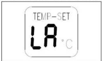
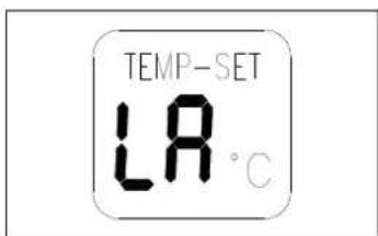
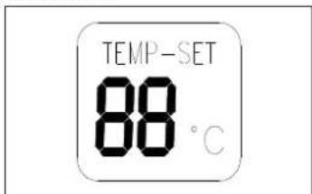
| 4 | TEMP-SET indicator: it shows the setting temperature at blank during screen protection. Codes are shown at malfunctioning or protection time. |
| 5 | LOCK indicator: when the user interface is locked, it always lights. |
| 6 | Water temp. indicator: when the actual water temperature exceeds 60 °C, it lights up. |
| 7 | Water temp. indicator: when the actual water temperature exceeds 50 °C, it lights up. |
| 8 | Water temp. indicator: when the actual water temperature exceeds 40 °C, it lights up. |
| 9 | OUTLET TEMP indicator: it displays water temperature of the upper part of the tank, which can be used. It always lights. |
| 10 | TIMER CONFLICT indicator: When the temperature you set through Wired Controller conflicts with that through User Interface, it lights up. |
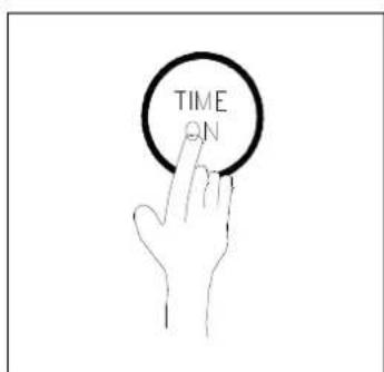
| 11 | TIME OFF indicator: It will light up when timing off mode is set, blanks during screen protection. |
| 12 | TIME ON indicator: It will light up when timing on mode is set, blanks during screen protection. |
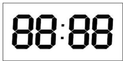
| 13 | CLOCK indicator: It displays present time, it blanks during screen protection. |
| 14 | E_HEATER MODE indicator: When the user sets the E-heating Mode, it lights up. |
| EN 14 | |
| 15 | HYBRID MODE indicator: When the user sets the Hybrid Mode, it lights up. |
| 16 | ECONOMY MODE indicator: When the user sets the Economy Mode, it lights up. |
4.3. Operation
4.4. Operation procedure
Preparation before running the appliance
When you run the appliance for the first time, all the indicators on the User Interface will light up for 3 seconds, and the buzzer will "didi" ring twice at the same time, and then display is lit up. After no operation for
1 minute, all indicators will go out automatically, except Water fill indicator which is flashing and the temp. indicator which is lighting.
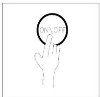
When the tank is full, please press the ON\OFF key, then the Water fill indicator will stop flashing and you can continue to function other settings. When all settings are finished, please press the ON\OFF key again and the Water fill indicator will go out. And then run the appliance.
When the appliance is running, if there is no operation or malfunction for 20s, the backlight of the display will go out automatically except the operation model, the outlet temp, the lock indicator. If there is no operation for 1 minute, the appliance will lock automatically, but the lock indicator would be right all time.
- Lock and Unlock
In order to prevent wrong operation, a special lock function has been designed. If there is no operation for 1 minute, the appliance will be locked automatically, and lock indicator will be displayed. When the appliance is locked, no keys can be operated.
Unlock:
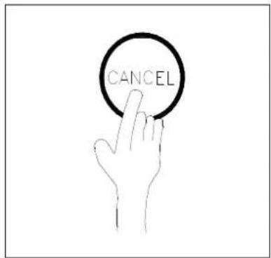
At the locking status of the display, long press the "CANCEL" key to remove it. At the screen protection of the display, press any key to activate the display, and then long press the "CANCEL" key to remove it. After removal of the locking mode, the Lock indicator will blank out and all keys could be
Clock set
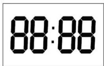
The clock is for a 24-hour system and the initial time is 00:00. To make a better use of this appliance, it is recommended to set the time for accurate local time. Every time powered off, the clock will be reset to the initial time 00:00.

15
Method for time set:
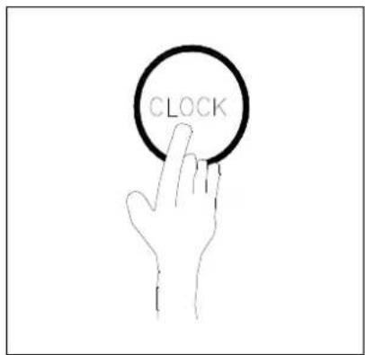
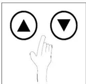
Press the CLOCK key, the minute of the the minute digit of the clock on the display starts flashing slowly.
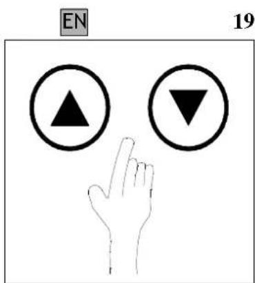
Press the ,UP" and ,DOWN" key, you can adjust the minute.
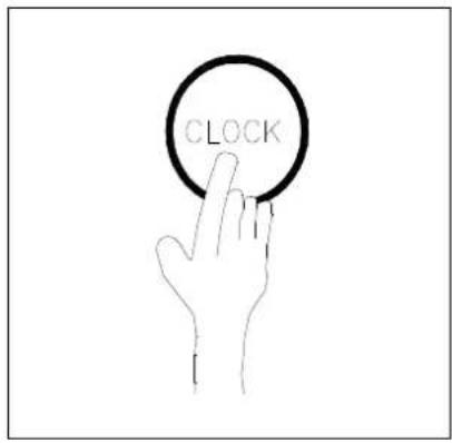
Press the CLOCK key again, the minute digit stops flashing while the hour digit starts flashing.
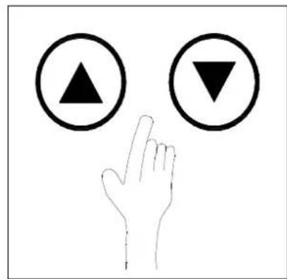
Press the ,UP" and ,DOWN" key, you can adjust the hour to set the clock.
Press the „CLOCK" key again and wait about 10 seconds, flashing stops and CLOCK SET is finished.
EN
16
Mode selection
The appliance is enhanced with three operation modes: Economy Mode, Hybrid Mode and E-heater Mode.
a) Economy Mode: the appliance heats water only by compressor drive according to heat pump principle. It is used when the ambient temperature is high (15^≤) .
b) Hybrid Mode: the appliance heats water basically by heat pump, but when the ambient temperature is low (15^≥) , the electric heater also starts to operate.
c) E-heater Mode: The appliance heats water only by electric heater. It is used when the ambient temperature is very low.
By default, the appliance operates in Hybrid Mode.
Mode Change:
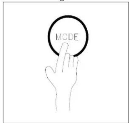
Press the MODE key, operation mode will be shifted among the three modes in a cycle, meanwhile the corresponding indicator on the display will light up.
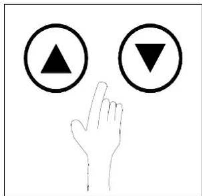
- Temperature set
The Temp displayed is the water temperature in the upper part of the tank. Default is 55^ and the Economy Mode setting range is 38 60^ , while the Hybrid and E-heater Mode setting range is also the same, 38 60^ .
Method for set
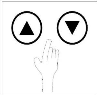
Press "UP" and "DOWN" key, you can increase or decrease water temperature.

When the set temperature is higher than 50^ , the HIGH TEMP indicator will light up.
Timer
The user can set up a running start time and a stop time specifically by the Timer function. The least number set for the time is ten minutes.
Time on: The user can set up a start time by this. The appliance will auto run one time between the set time and 24:00 on the same day.
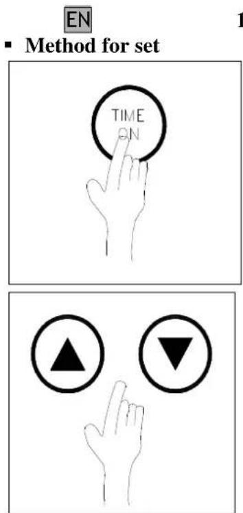
Press the TIME ON key, the minute digit of the clock ont he display starts flashing slowly.
Press „UP" and „DOWN" key, you can adjust the minute.
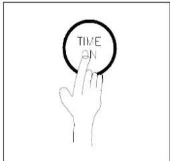
Press the TIME ON key again, the minute digit stops flashing, and the hour digit starts.
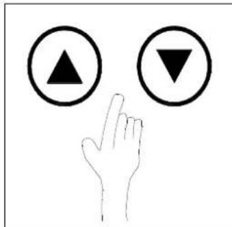
Press „UP" and „DOWN" key, you can adjust the hour.
Press the TIME ON key again and wait about 10s, flashing stops and ON TIMER set is finished.
- Cancel:
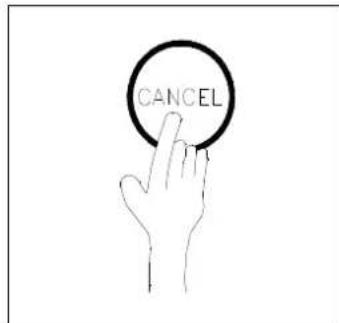
In the unlocked state, press the CANCEL key for 1 second and the TIME ON function will be cancelled.
EN
18
Time on and Time off: Users can set up a running start time and a stop time. When the start time is earlier than the stop time, the appliance will run between the set time. When the start time is later than the stop time, the appliance will run between the start time today and the stop time next day, when the users set up a running start time and a stop time at the same time, the stop time will be delayed by ten minutes automatically.
Method for set

Press the TIME ON key, the minute digit of the clock on the display starts flashing slowly.

Press the ,UP" and ,DOWN" key, you can adjust the minute.
Press the TIME ON key again, the minute digit stops flashing and the hour digit starts flashing.
Press „UP" and „DOWN" key, you can adjust the hour.

Press the TIME OFF key, the minute digit ont he display starts flashing slowly.
Press the ,UP" and ,DOWN" key, you can adjust the minute.

Press the TIME OFF key again, the minute digit stops flashing and the hour digit starts flashing.

Press the „UP" and „DOWN" key, you can adjust the hour.
Stop operation for about 10 seconds, flashing stops and TIME ON + TIME OFF set is finished.
- Cancel:
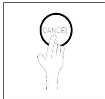
In the unlocked state, press the CANCEL key for 1 second, the TIME ON + TIME OFF functions will be cancelled.
REMARK
Time on and Time off functions can not be set to the same time. If they are the same, the stop time will be delayed by 10 minutes automatically. For example, if Time on and Time off are set to 1:00 at the same time, the stop time will be adjusted to 1:10 automatically.
The Time off function can not be used alone. The key can be used only after Time on has been set. The user can press the on\off key manually beyond the Timer range.

20
Power On and Power Off: Press Power On/Power Off button when the setting above has been finished and the system will run according to the setting. And simply press the same button to stop it.
Operation status
The light alarm code from the screen of SET TEMP. will appear and remind the user that the ambience temperature does not meet the operation conditions of the heat pump unit (beyond the range of -7 43^ ). The user can switch the Economy Mode to E-heating Mode to ensure enough volume of hot water according to needs. The appliance will return to operation pre-status automatically, when the ambience temperature meets the operation conditions of heat pump mode and the error light alarm will disappear at the same time so the screen display will become normal.
Warning code of disagree with heat pump mode.
In case of continuous 20 hours when the season ambient temperature does not meet the heat pump operation requirements (beyond the range of -7 43^ ), "LA" error code will be displayed at TEMP SET window and the ALARM indicator will flash simultaneously signing that the temperature does not meet the heat pump performance. This time, only E-heating Mode can be set under these circumstances. Please switch to E-heating Mode manually to ensure that the quantity and temperature of hot water supplied should be adequate. When this is the case, the error code disappears and indicator alarm stops flashing and everything sets back to normal operation
The light will glitter in error.
Warning code of disagree with heat pump mode.
Error shooting
If some error happens, the buzzer will buzz 3 times every other minute and the ALARM indicator will glitter fast. Press CANCEL for several seconds to stop the buzzer but the light will keep glittering.
The light will glitter in error.

Press CANCEL key to stop the buzzer.
The error code from the screen of SET TEMP. will be displayed when malfunctioning happens, the system then displays an error code after one minute. Press the SET TEMP key again to set the temperature on the screen
The error code is displayed.
When malfunctioning happens in Economy Mode, the system switches to E-heater Mode and goes on operating. When some error happens, the system could be used under some circumstances, but it can not reach the expected efficiency. Please contact your contracted distributor for help. Error code explanation (See Table 4.5-1.)
WARNING!
The cover of the electric heating can be removed only by a technician; failure to this warning may cause electric shock or other danger.
4.5 Error code explanation
Table 4.5.-1.
| Display Malfunctioning description | |
| E0 | Error of sensor T5U |
| E1 | Error of sensor T5L |
| E2 | Tank and wired controller communication error |
| E3 | Discharge pipe temperature sensor error |
| E4 | Evaporation pipe temperature sensor error |
| E5 | Ambient temperature sensor error |
| E6 | Discharge pipe temperature sensor error |
| E7 | Heat Pump system error |
| E8 | Electric leakage error. The control indicates electric leakage error at L, N > 14mA. |
| E9 | TH sensor condenser failure |
| P1 | System high pressure protection error |
| P2 | Discharge pipe temperature overhigh error |
| P3 | No current flowing in compressor |
| P4 | Compressor overloading error |
| P8 | No current flowing in electric heater |
| P9 | Upper e-heater overloading error |
| LA | Ambient temperature is not fit for heat pumps, change the mode to E-heater mode |
Remark:
If you perceive defective operation of the appliance, please turn to either a contracted service shop or our to our customer service.
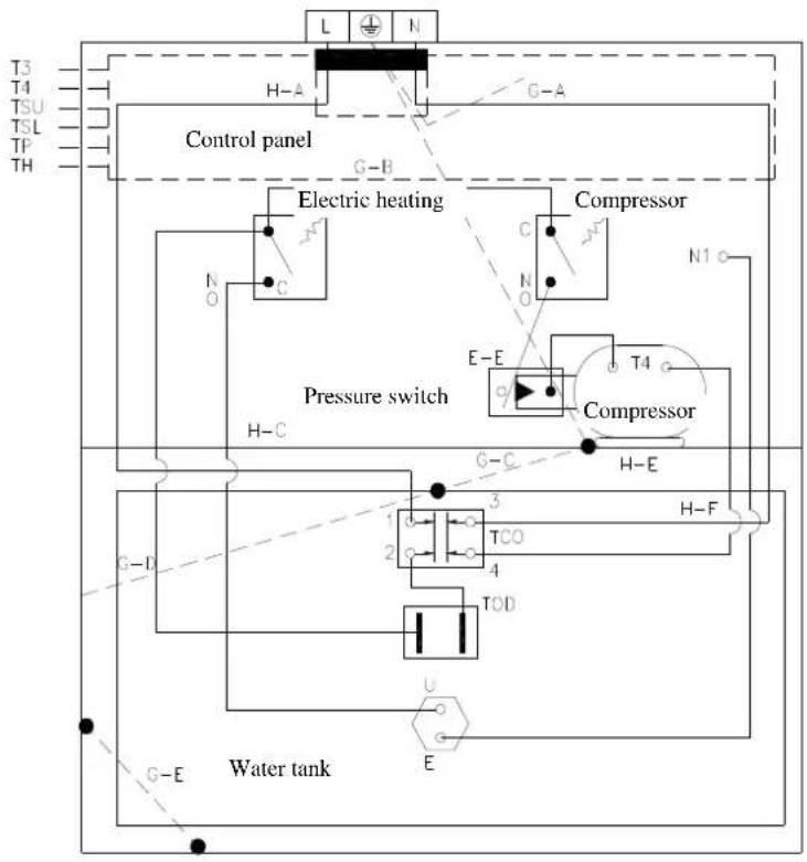
T3: Pipe temperature sensor
T4: Environmental temperature sensor
T5L:Tank temperature sensor (lower)
TSU:Tank temperature sensor (upper)
TP: Discharge temperature sensor
TH: Air reflow temperature sensor
5. MAINTENANCE
5.1. Planned preventive maintenance to be performed by the user
WARNING!
The operations explained below can only be performed when the appliance is not operating, so it is switched off and the external switch is set into "OFF" position.
It is recommended to perform the following operations at least every second month:
a) safety valve: in order to prevent obturation and remove limescale deposition, the safety valve has to be operated regularly.
b) external coverage: clean it with wet cloth dipped into soapy water. Do not use pesticides, solvents or aggressive cleaning supplies.
5.2. Routing check of heat pump water heater
In order to reduce the number of possible errors to the minimum and to ensure perfectly efficient operation of the appliance (which means maximum performance besides minimal operation costs), it is recommended to ask the service technician authorized by area at least every second year to perform overall check of the appliance. The planned preventive maintenance operations to be performed by the service technician are the following:
5.3. Technical support
Before contacting the service center or the service technician authorized by area in case of a potential error, please check whether the error is caused by unique circumstances, like for example, temporary power cut or water pipeline shutdown.
In case of reparation, original spare parts are to be used exclusively, and any type of reparation work can only be performed by a qualified technician. Failure to consider these recommendations may endanger the safety of the appliance and it invalidates the responsibility undertaken by the manufacturer.
5.4. Disposal of water heater
The appliance contains cooling gas of R134a type, which must not be emitted in the atmosphere. If the water heater is put outside operation for a longer time, please ensure that only qualified technicians perform the disposal of the appliance. The product complies with EU Directive No. 2002/96/EC.
The dustbin symbol lined through displayed on the data label of the appliance means that when the product reaches the end of its life-cycle, it should be disposed of separately from other household waste and it should be transported to waste disposal site dedicated to electric or electronic devices or it should be transported back to the contracted distributor if the user buys a new product of the same type. It is the task of the user to transport discharged and dismounted appliance to the adequate waste disposal site. Proper and separated collection of dismounted appliance and then its eco-compatible recycling, handling and disposal contribute to the prevention of effects damaging the environment and human health, and thus, they support recycling of materials incorporated in the product.
TECHNICAL INFORMATION FOR INSTALLING TECHNICIANS
6. USEFUL RECOMMENDATIONS
6.1. Qualification of installing technicians
WARNING!
Putting into operation and first start up of the appliance can only be performed by a technician according to all related effective national regulations or legal requirements or any requirements defined by local authorities and public health organizations.
Heat pump hot water tank contains R134a cooling agent in a quantity enough for its operation. The cooling fluid does not damage the ozone layer of the atmosphere, it is not flammable or explosive, but only the authorized personnel is allowed to perform any maintenance or repair work on the cooling circuit, using adequate equipment.
6.2. Usage of installation, usage and maintenance manual
WARNING!
Improper installation may cause personal injuries or injuries in animals or damage to objects. The manufacturer shall undertake no responsibility for these injuries or damages.
The person performing installation or putting into operation the appliance is obliged to comply with the instructions of this manual. After finishing the installation, the person performing installation is obliged to inform and train the user on the operation of the water heater and on proper execution of the operations.
6.3. Check of heat pump water heater
During handling the appliance or opening the packaging, please, follow the instructions explained in points 1.4 and 1.5 of chapter GENERAL INFORMATION carefully.
During the removal of the packaging, please, check whether the appliance is intact and whether all required parts are included in the package.
6.4. Safety precautions
The explanation of the symbols used in the table below is described in details in point 1.3, chapter GENERAL INFORMATION.
| warning danger | |||
| 1. | Protect connection pipes and wires from any possible damage. | Danger of electric shock caused by touching the parts under power. | △ |
| Flood caused by water leaking from damaged pipes. | △ | ||
| 2. | Ensure that the location of installation and any system to which the appliance is connected fully comply with effective relevant regulations. | Electric shock caused by touching the parts that are put into operation improperly or that are under power. | △ |
| Damage of the appliance caused by improper operation conditions. | △ | ||
| 3. | Use manual tools and equipment adequate to the purpose (it is especially important to ensure that the tools are not used up, their handles are intact and fixed safely). Use tools and equipment in a proper way, so that they can not fall down from above. Put the tools and equipment back into their places after use. | Personal injury caused by flying chips or spills, dust inhalation, hit, cut or stabbed injuries or bruises. | Δ |
| Damage of the appliance or surrounding objects caused by falling chips, beating or cutting. | Δ | ||
| 4. | Use electric equipment adequate for the purposes. Use the equipment properly. No feeder wires should be located in the passages. The equipment should not fall down from above. Disconnect them from the power system and put them back into their places after use. | Personal injury caused by flying chips or spills, dust inhalation, beaten, cut or stabbed injuries or bruises. | Δ |
| Damage of the appliance or surrounding objects caused by falling chips, beating or cutting. | Δ | ||
| 5. | Parts should be cleaned from fur according to instructions on the safety data sheet of the applied product, besides airing of the location and wearing protective clothing. Avoid mixing different products and protect the appliance and the surrounding objects. | Personal injuries cased by acidic materials touching the skin or the eyes; inhalation or swallow of harmful chemicals. | Δ |
| Damage of the appliance or surrounding materials caused by corrosive effect of acidic materials. | Δ | ||
| 6. | Ensure that portable ladders are placed safely and that they are adequately resistant, the steps are intact and slippery free. The ladder must not be moved when somebody is on it. A person should always supervise the operations. | Personal injuries cased by fall down or by accidental closing of the standing ladder. | Δ |
| 7. | Ensure that adequate hygienic conditions are produced in consideration of lighting, airing and stability of the relevant structure of the place of work. | Personal injury caused by hit, fall, etc. | Δ |
| 8. | Wear individual protective clothing and equipment during each work phase. | Personal injuries caused by electric shock, falling chips or spills, dust inhalation, shaking, cut or stabbed injuries, bruise, noise or vibration. | Δ |
| 9. | Each operation to be performed within the appliance should be performed with due caution, in order to avoid sudden touch of sharp parts. | Personal injuries caused by cut or stabbed injuries, bruise. | Δ |
| 10. | Before handling the appliance, discharge all parts that may contain hot water, through performing water discharge, if necessary. | Burning marks. | Δ |
| 11. | Mount electric connections with wires of adequate cross section size. | Fire caused by overheating as a result of electric power flowing through undersized wires. | Δ |
| 12. | Ensure the protection of all areas surrounding the appliance and the work area with adequate materials. | Damage of the appliance or surrounding objects caused by falling chips, hit and cut. | Δ |
| 13. | Handle the appliance carefully, using adequate protective tools. | Damage of the appliance or surrounding objects caused by shaking, hit, cut or contusion. | Δ |
| 14. | Organize all materials and equipment in a way ensuring easy and safe handling, avoiding accumulation of materials that may lead to their falling down or leaning away. | Damage of the appliance or surrounding objects caused by shaking, hit, cut or contusion. | Δ |
| 15. | Set all safety and control functions concerned by any work performed on the appliance into default state and ensure that they operate properly before re-starting the appliance. | Damage or shutdown of the appliance caused by unregulated operation. | Δ |
Please follow the general warnings and safety precautions listed in the previous chapter and please comply with them strictly.
7.1. Placement of water heater
WARNING!
Before starting any installation operation, please ensure that the planned operation location of the water heater fulfils the following requirements:
a) It should be installed in a location larger than a floorspace of 8m^2 . Do not place the appliance in a location that may provide favourable conditions for the creation of ice. Do not place the appliance into a location where another appliance works that requires air for its operation (i.e. gas furnace, water heater operated by gas, etc.) It is not allowed to use the hot water tank outdoors or at a place exposed to rain.
b) In order to ensure adequate operation of the appliance and to ease maintenance, the selected location has to possess suitable safety distances as measured from the walls and the ceiling (Figures 7.1.-1 and 7.1-2.)
c) Feet fixing: Make sure that the flooring is flat enough, possessing adequate stability. With the help of the „drill frame" (usage manual), set the positions of the feet fixing, taking into consideration deployment sizes indicated on figures 7.1.-1, and 7.1.-2. of the usage manual. Mount the 3 feet fixing items attached to the appliance with screws of M8 size and metal hit anchor drilled into the flooring as minimum (M8x75), while the feet fixing is positioned according to figure 7.1.-3. Fix the setable feet of the appliance at a distance of min. 26mm (see figure 7.1.-4.) Push the appliance carefully into the direction of the feet fixing screwed down in a way that the setable feet are hit up in the open mortice of the feet fixing (figure 7.1.-5.).
If the appliance is operated without any feet fixing, it might turn upside down. In this case, the manufacturer shall not be liable to any damages emerged.
Air outlet
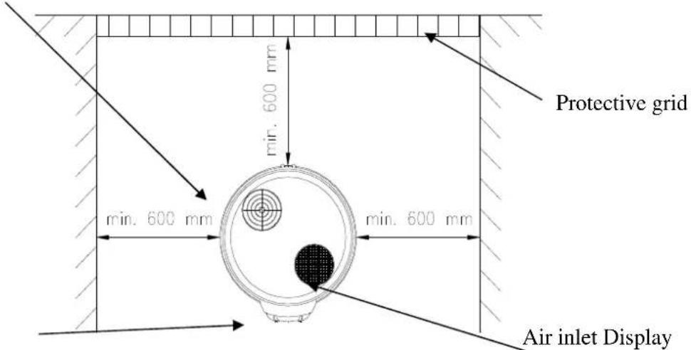
Figure 7.1.-1.
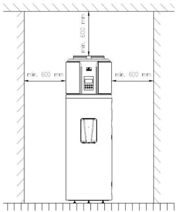
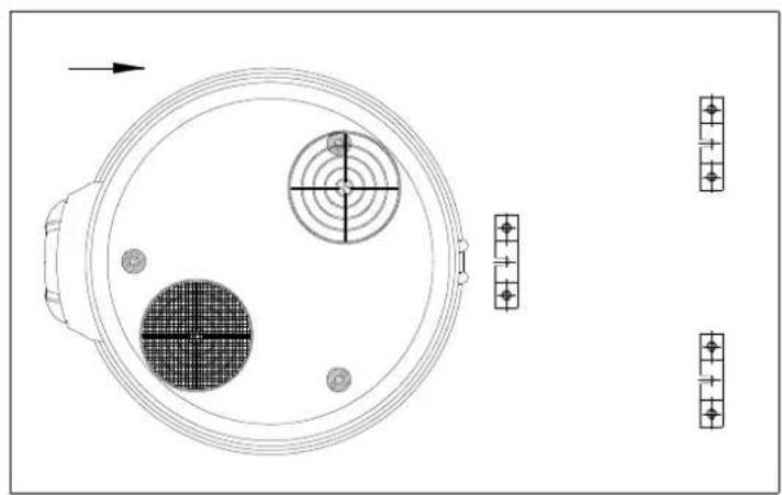
Figure 7.1.-2.
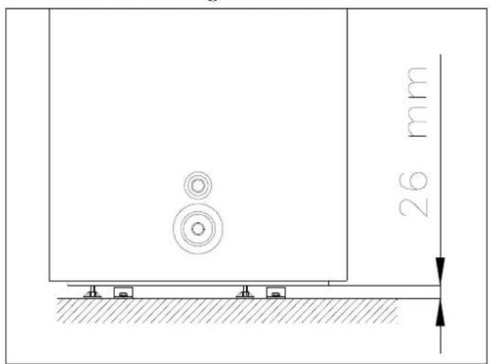
Figure 7.1.-3.
Figure 7.1.-4.
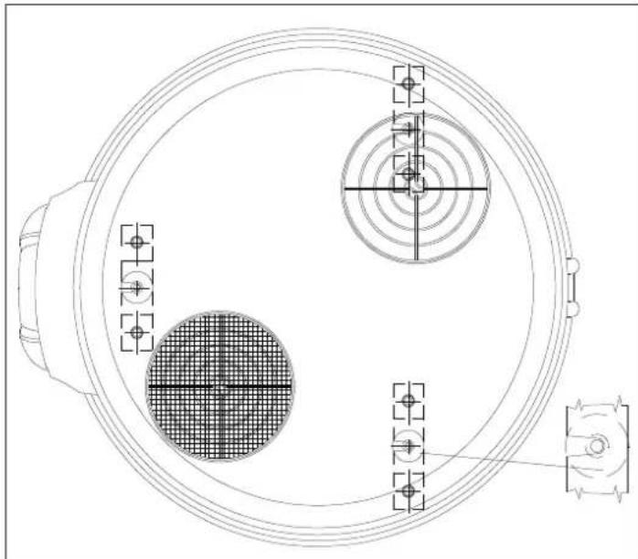
Figure 7.1.-5.
a) The selected location must be ready to house a discharge opening for condensate water connected to the upper part of the appliance with a flexible circuit.
b) Please ensure that the location of operation and electric and hydraulic systems to which the appliance will be connected fully comply with all relevant regulations.
c) The selected location has to possess (or to be able to house) a single phase 230V 50Hz external switch.
d) According to the definitions of relevant regulations, the selected location has to comply with IP protection class (protection against liquid penetration).
e) Do not expose the appliance to sunlight, not even through any window.
The appliance must not be exposed to effects of especially aggressive materials, i.e. acidic gases environment saturated by dust or gas.
The appliance must not be mounted directly to phone line without overvoltage protection.
h) The appliance must be placed and operated as close to the usage points as possible, in order to limit the diffusion of heat along the pipeline.
i) Adequate electric power system, water pipeline and sewage system should be ensured on the location of the operation. (floor drain).
j) In order to reduce heat loss due to hot water pipe, please install the appliance close to hot water usage locations, if possible. In case of larger distances, it is rational to equip the hot water pipe with heat insulation.
k) Unused connection branches of the hot water tank must be closed and equipped with heat insulation.
1) Review measure diagrams (Figure 2.8.-1.)
7.2. Duct connection ways
Air outlet Air inlet
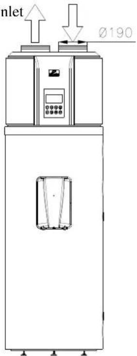
Figure 7.2.-1.
Air outlet
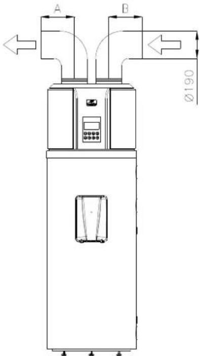
Figure 7.2.-2.
Air inlet
Air inlet and air outlet are connected to air duct. A + B≤ 10m
Duct description
| Duct size Dimensions(mm) | Straight-line pressure drop (PA / m) | Straight-line length(m) | Bent pressure drop (PA / m) | Bent quantity | |
| Round duct | Ø 190 | ≤2 | ≤10 | ≤2 | ≤5 |
| Rectangle duct 190x190 | ≤2 | ≤10 | ≤2 | ≤5 | |
Remark: It is better to connect the air duct to air outlet than to air inlet.
Remark: Due to operation with air duct, part of air flow and heat pump capacity is lost in the system.

Air outlet
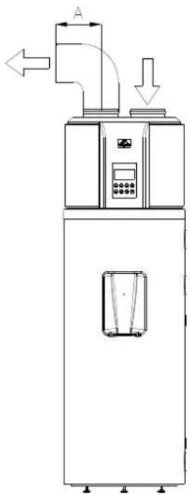
Figure 7.2.-3.
Air inlet
Air inlet is not connected to air duct, but air outlet is connected to air duct. A ≤ 10 m Recommendation: Use it in case of heat surplus or in winter in case of indoor heat surplus.
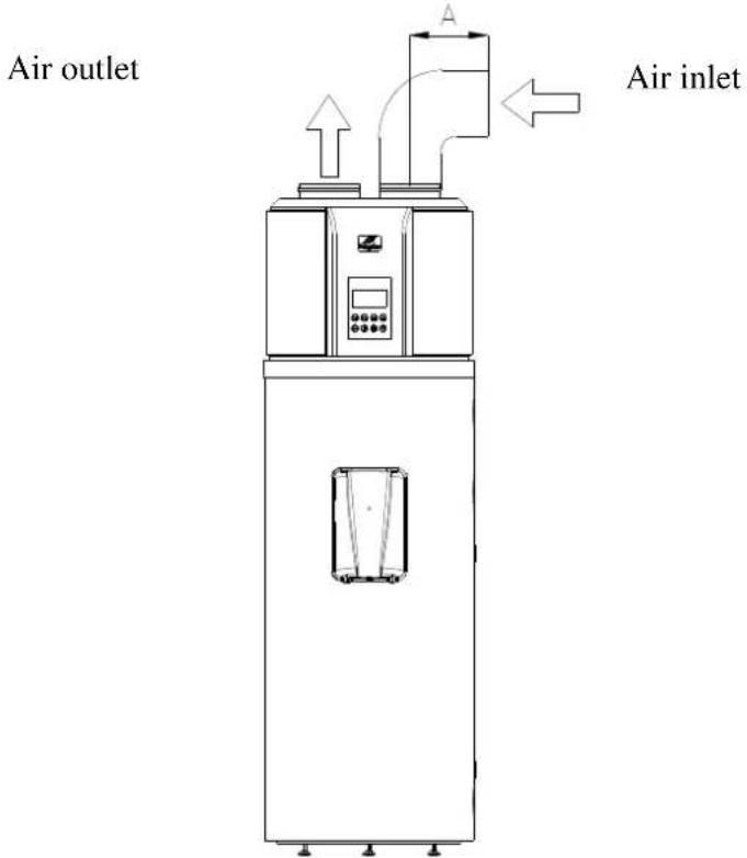
Figure 7.2.-4.
Air inlet is connected to air duct, but air outlet is not connected to air duct. A ≤10m
Recommendation: This connection way used in the summer refreshes the air of the indoor space.
REMARK
a) Due to connection with air duct, part of air flow and heat pump capacity is lost in the system.
b) If the air outlet of the main unit is connected to canvas air duct, condensate drops may be produced outside the canvas air duct during the operation of the main unit. Please, ensure drainage of condensate water. In this case, it is recommended to mount the heat insulation layer outside the air duct outlet.
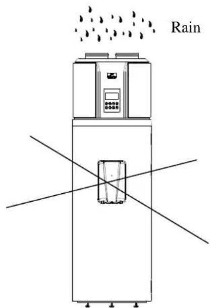
Figure 7.2.-5.
Putting into operation HB300(C) hot water tank in a closed space.
It is forbidden to operate HB300(C) hot water tank outdoor or exposed to rain or moisture.
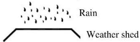
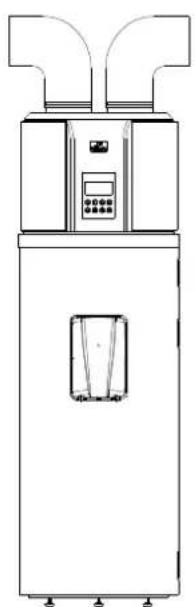
Figure 7.2.-6.
If the HB300(C) hot water tank is connected to air duct reaching to outdoor, reliable water-resistant protection needs to be ensured for the air duct, to avoid that rainwater enters the appliance.
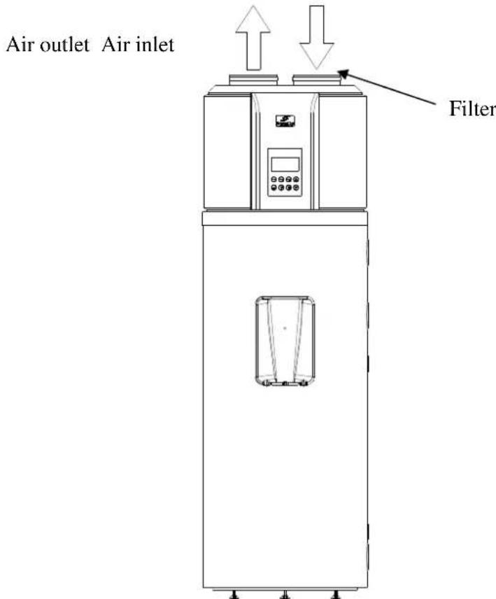
Figure 7.2.-7.
Figure 7.2.-8.
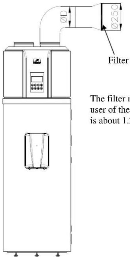
The filter must be mounted by the user of the appliance, the mesh size is about 1.2mm
Filter installation to the air inlet of the appliance. If the appliance is connected to air duct, a filter must be mounted to the air inlet of the air duct.
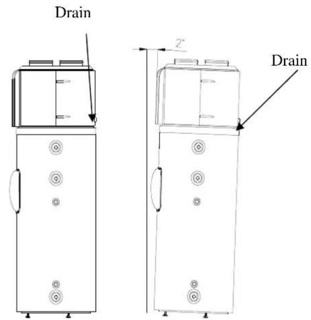
Figure 7.2.-9. Figure 7.2.-10.
In order to drain condensate water continuously, please install the appliance on a horizontal floor. If this is not possible, please ensure that the drain vent is at the lowest possible place. It is recommended to place the appliance in a way that the inclination angle between the appliance and a vertical line is not more than 2^ .
7.3. Pipeline connection
It is forbidden to connect the appliance with a hose pipe. Galvanized steel pipe, plastic pipe and red copper pipe can equally be used as cold water pipe or hot water pipe. In case of connecting red copper pipes to the water pipeline system, the use of insulating intermediate pieces is compulsory.
The package of intermediate pieces distributed by HAJDU Zrt. are sold in outlay of 2 items in contracted shops of HAJDU Zrt. and in the general commerce. One of the intermediate pieces should be mounted directly to the hot water pipe of the tank, while the other should be mounted between the fittings already mounted and the red copper water pipeline system.
In case of connection without intermediate pieces, the guarantee on the appliance will be invalidated.
IT IS AT THE RISK OF DEATH AND THEREFORE IT IS FORBIDDEN TO PUT THE WATER TANK AND THE HEAT EXCHANGERS UNDER A PRESSURE LARGER THAN THE PERMITTED OPERATION PRESSURE (0.7 MPa) !
During connection to the water pipeline system, it is compulsory to keep the building order of the fittings according Figure 7.3.-1., as proper operation of the appliance highly depends on that.
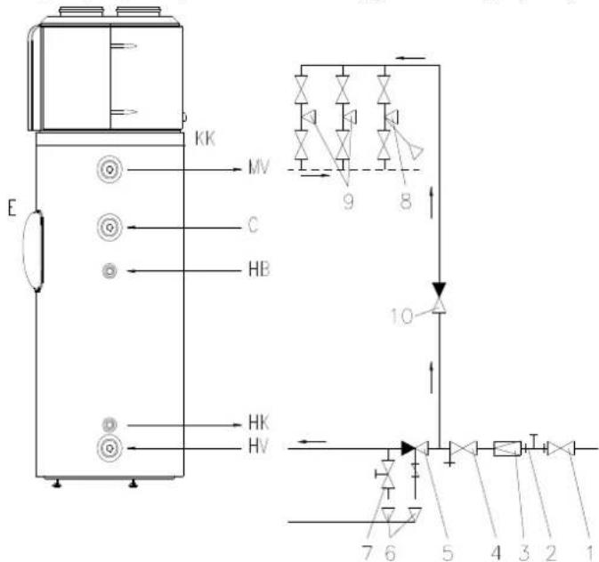
Figure 7.3.-1.
HV - Cold water
MV - Hot water
E -Electric heating
HB - Heating agent inlet from heat exchanger or external heat exchanger (in case of type HB300C)
HK - Heating agent outlet from heat exchanger or external heat exchanger (in case of type HB300C)
C - Circulation pipe branch
KK - Condensation outlet
1 -Closing valve
2 -Manometer
3 -Pressure reducing valve (only above water pipeline pressure above 0,6MPa
4.-Y filter
5 -Combined safety valve
6 -Drain outlet (into sewage system)
7 - Discharge valve
8 -Faucet (with shower)
9 -Faucet
10 -One-way valve
The combined safety valve must be connected to the cold water branch considering the flow direction indicated by the arrow. The maximum distance between the appliance and the valve is 2m , and two bends (arc, knee) are permitted. The appliance has to be equipped with safety valve controlled for an operation pressure of max. 7 bar. The safety valve has to be mounted directly before the tank onto the cold water pipe branch, in a frost-free environment. The drainage pipe has to be connected to the safety valve in a way that it is always directed downwards and located in a frost-free environment. The feeding pressure of incoming cold water must not exceed 5.25 bar pressure in case of valve with operation pressure of 7 bar. In case of valve with lower pressure values, maximal feeding pressure has to be defined concerning mini-maxi tolerance limits of the safety valve. If it exceeds this value, pressure reduction device should be connected in front of the safety valve.
The safety valve is not an accessory of the appliance.
IT IS FORBIDDEN TO BUILD WATER PIPELINE FITTING BETWEEN THE VALVE AND THE APPLIANCE.
Before mounting the valve, the cold water pipeline must be flushed thoroughly, in order to avoid any damage caused by any possible pollution. The combined safety valve contains a one-way valve. Therefore, it is not needed to mount a separate one-way valve. During the heating, the expanding water has to leak through the drainage pipe branch of the combined safety valve. During installation of the valve, one should pay attention to ensure that this leaking remains visible.
IT IS FORBIDDEN TO CLOSE THE DRAINAGE PIPE BRANCH OR TO DIVERT WATER LEAKING IN A NON-VISIBLE WAY.
If the pipeline system pressure exceeds the value of 0.6MPa - only in a temporary way -, a pressure reduction valve has to be mounted in front of the hot water tank, at the location of item
No. 3 as described in Figure 7.3.-1. In case of lacking pressure reduction valve, the safety valve will leak besides heating under this pressure. It is the task of the user to purchase and mount the pressure reduction valve. If the combined safety valve is connected to the hot water tank without the reducing device, in order to discharge the hot water tank, a discharge faucet or valve should be mounted to the cold water pipe of the appliance, adding a standard T-shaped fitting. It is the task of the user to purchase the valve (faucet). An arbitrary number of taps and mixing faucets can be mounted on the hot water tank. It is rational to block the flow back of the hot water through the outlet towards the cold water pipeline system by mounting a one-way valve in the cold water pipe in front of the taps. A closing valve needs to be mounted in the cold water pipeline leading to the tank in front of the fittings (combined safety valve, one-way valve, etc.) With the help of this closing valve, both the hot water tank and the water pipeline fittings can be disconnected from the water pipelines system (in case of failure or other maintenance work).
7.4. Electric connection
- The hot water tank should be connected to the electric system only through permanent connection. It is forbidden to apply any wall socket.
- The current of the electric system has to be connected to the hot water tank through an all-pole disconnection device, which has at least 3mm separation distance in all poles.
- The required diameter per string of the electric system wire with 3 strings is: 2.5mm2 - 4mm2 depending on performance as described on the data table.
The wires adequate for connection to the electric system are the following:
Adequate type: H0 5VVF H0 5RRF
Connection with wire protection tube is not allowed.
- The connection wire and the wire with green/yellow colour mark have to be connected in the terminal block. The plastic wire driver marked with a label located at the lower part of the cover of the fitting house has to be broken out. ("Break out for connection") The overhang part of the rubber wire driver, which is placed in the bag attached to the appliance, has to be cut, then the wire driver has to be stitched to the electric system wire. The connection wire has to be connected in the terminal block of the left side according to phase label (L, N, The wire fixing and the bent clamp have to be tightened finally, then the wire driving rubber has to be fitted to the lower horizontal surface of the cover frame in a way that it has to protect electric parts against any possible water inflow, after mounting the cover.
Figure 7.4.-1. shows the electric connection diagram of the hot water tank, which can also bee seen on the cover of the fitting house.
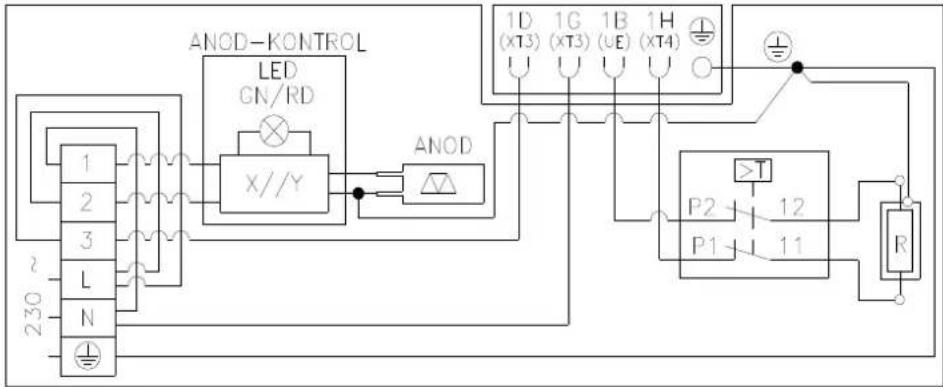
Figure 7.4.-1.
IT IS FORBIDDEN TO OPERATE THE HOT WATER TANK WITHOUT ANY PROTECTIVE EARTH The protective earthing has to comply with the instructions of the Hungarian Standard MSZ 2364.
7.5. First start up
Before first start up of the appliance, please, check the following elements:
- Adequate installation of the appliance;
- Adequate connection of water pipes and electric wires;
- The leaking of cooling pipe has been tested;
Efficient water discharge pipe.
Full insulation protection;
Adequate earthing; - Adequate power source;
- No obstacle to air inlet and air outlet;
There is no air in the water pipeline and all the valves are in open position;
Efficient electric leak protection is operating;
Water inlet pressure is sufficient (≥ 0,15MPa)
After being connected to the water pipeline system and the electric power system, the hot water tank has to be filled up with water from the household water supply system. The tank must be filled up with water before switching on the heating. During filling the tank up with water, open the hot water valve of the closet tap while keep all the other valves closed. Then open the closing valve mounted in the cold water pipe (Figure 7.3-1., item No. 1.). The tank is filled up when water appears on the tap. For flushing purposes, the water must be flown for some minutes, then you can close the valve of the hot water.
PLEASE TURN TO A TECHNICIAN TO CHECK THE FIRST HEATING.
Perform an eye check to decide whether connections of edges and pipe fittings are leaking or not - and tighten them carefully, if necessary. The appliance can be connected to the electric power system only after this check. In order to switch the heat pump of the water heater in a mode, press the ON/OFF key located on the control panel. Before setting the clock and other parameters or programs, please follow the instructions of chapter 4.
FOR PERSONNEL AUTHORIZATION TO PERFORM MAINTENANCE
8. MAINTENANCE INSTRUCTIONS

WARNING!
Please follow the general warnings and safety precautions listed in the previous chapter and please comply with them strictly.
Any operations and activities has to be performed by qualified personnel (so they have to possess expertise as required by effective regulations).
WARNING!
Before repair or maintenance, the appliance always must be switched off and the external switch must be turned into "OFF" position.
8.1. Appliance discharge
Water drainage can be performed through the blow off button (faucet) mounted in front of the hot water tank or through the combined safety valve, turning the button in the direction indicated by the arrow, through the water outlet tube. Before water drainage, the valve closing pipeline connection and the cold water faucet have to be closed, while the hot water faucet has to be kept opened during water drainage.
ATTENTION! HOT WATER MAY OUTFLOW DURING WATER DRAINAGE!
If you perceive water leaking or any malfunctioning from the interior of the appliance, switch it off from the water pipeline system immediately with the help of the closing valve.
8.2. Storing and combined safety valve
In order to ensure safe operation, it is rational to turn to a plumber to check the appliance and the correct operation of the combined safety valve every now and then (in every year). Furthermore, it is recommended to blow off the valve every month or every second month through turning the blow off button of the safety valve in the direction indicated by the arrow. This way, the valve seat is cleaned from any possible pollution (sand grains, scale, etc.)
8.3. Active anode
Besides enamel coverage, the hot water tank is protected by anode against corrosion, so it is essential that the tank always possesses an active anode of adequate size. Therefore the state of the active anode must be checked every second year by a contracted service shop. This is also a condition for extra warranty related to the tank (see the commercial warranty). If the diameter of the anode shrinks to appr. 10mm , it has to be replaced.
It is extremely important that the active anode has good contact with the tank. Therefore, in case of mounting a new anode or performing any other repair work, the connection of the active anode and the earthing screw has to be performed in a way that the electric connection must drive electricity well.
8.4. Scale removal
Depending on the quality of the water, scale deposition may occur on the heater exchanger or on the tank. The scale deposited on the heater decreases heating efficiency. So, it is necessary to clean the hot water tank from scale every second year.
It is strictly forbidden to apply any sharp metal object or acid to remove scale deposited on the heat exchanger, the close cover and its fittings. Please use cleaning and scale removal supplies available in commerce.
Scale can be removed from the interior part of the tank manually, through the fitting opening. It is rationale to flush the tank with water ray after scale removal.
8.5. Prevention of frost damages
If temperature may fall below the freezing point in the location of the hot water tank, the heating of the tank must not be switched off or the tank must be discharged in periods of frost danger.
8.6. In case of indirect heating
OVERHEATING PROTECTION MUST BE PERFORMED BY THE INDIRECT HEATING EQUIPMENT!
8.7. Air filter
Clean the air duct every month as this influences heating performance! If the filter has been mounted directly into air inlet (i.e. air inlet is not connected to air duct), dismounting and cleaning of the filter can be performed in the following way: the air inlet closing ring has to be turned counter-clockwise, the filter must be removed and perfectly cleaned and then it must be put back to its place.
8.8. Shutdowns not caused by errors
a) 3-minutes protection
When the appliance is under power, one must wait 3 minutes to protect the compressor at immediate start-up after shutdown.
b) If the appliance launches a self-protection mechanism and then shuts down, please check the following:
When the power indicator lights up, it may happen that the appliance does not fulfil all the conditions for system start up when being switched on. One should also check that air inlet or air outlet are not blocked or no strong draught reaches the air outlet.
c) Defreezing
The evaporator may freeze in a wet and cold environment, so it can reduce water heating performance. This time, the appliance is set to stop water heating, changes to defreezing and starts water heating only then.
During defreezing, the fan stops, the four-direction valve turns the way of flow and the compressor operating continuously.
Defreezing may range from 3 minutes to 10 minutes, depending on the external environment and the frost.
d) Temperature display
When the appliance stops, temperature decrease due to heat release is quite normal. The system is started automatically after falling back to a certain heat degree.
During water heating, the indicated water temperature may decrease for a while or it can not increase due to heat exchange of the water. When the tank has fully reached the pre-set temperature, the appliance stops automatically.
8.9 Errors and solutions
| Malfunctioning Reason | Solutions | |
| The outlet water is cold. The display is dark. | Check whether power supply exists Outlet water is set an a low temperature; Outlet water temperature controller is damaged; Circuit board of indicating indicator is damaged; | Set outlet water at a higher temperature; Contact the technician. |
| No hot water from the outlet. | Tap water has been cut away; Water pressure is too low; Inlet valve has been closed. | It will return to normal after water supplied; Use it when the pressure is higher; Open the inlet water valve. |
| Water leakage The joints | on the pipeline are not sealed well. | Check and reseal all the joints. |
8.10 Self-protective mechanisms of the appliance
a) In case of self-protection, the appliance shuts down, starts auto-check and re-starts when the defensive mechanisms are put into operation.
b) During the launch of self-protection, the buzzer will buzz every other minute and the ALARM indicator will glitter fast, the error code and water temperature are displayed at one after the other. Press CANCEL for 3 seconds to stop the alarm. The self-protection mechanisms solve the error and the error code disappears from the display.
c) The appliance shall launch its self-protective mechanisms among the following circumstances:
c.1) Air inlet or air outlet is blocked;
c.2) The evaporator is covered by too much dust;
c.3) The power source is inadequate (it exceeds the voltage range of 230V )
REMARK
In case of self-protection of the appliance, it has to be disconnected from the electrical power system manually and restarted after solving the error.
1) Water temperature display
1.a) The water temperature data concerns water in the upper part of the tank (above 1/4), which is used by the user, but it does not cover all the quantity of the water stored.
1.b) The 6 indicator displayed next to the water temperature data measures the temperature of the lower part of the water. When water temperature exceeds 50^ , blue and yellow indicators are lit up. In case of water temperature of 60^ , the blue, yellow and red indicators are lit up and finally, when all the collared indicators are lit up, water has reached the desired temperature.
1.c) During water usage, it might happen that the temperature of the lower water part decreases while the upper part temperature is still high, this time, the appliance starts heating of the lower part. This is considered to be normal operation.
2) Error shooting
3) In case of frequent error, the appliance changes into Standby mode and stays to be operative, but at a definitely lower efficiency than earlier. Please, turn to a technician.
3.a) In case of serious error, the system can not operate further. Please, turn to a technician.
3.b) In case of occurrence of error the buzzer will buzz every second minute, the ALARM indicator will glitter faster, the ALARM indicator is lit up and the error code and water temperature are displayed one after the other. In order to switch off the alarm, please, press the CANCEL button for 3 seconds!
4) Restart after long shutdown
When the appliance is restarted after shutdown for a longer period (including pilot mode), it is evident that outlet water is not clean. This time, the faucet must be kept open and outflowing water becomes clean soon.
Sommaire