
T32100 - Car radio Ultimate - Free user manual and instructions
Find the device manual for free T32100 Ultimate in PDF.
| Product Type | Car Audio Amplifier |
| Brand | Ultimate |
| Model | T32100 |
| Amplifier Class | AB (for T3 series) |
| RMS Output Power (4 ohms) | 250 W x 1 |
| RMS Output Power (2 ohms) | 320 W x 1 |
| Max Output Power (4 ohms) | 440 W x 1 |
| Max Output Power (2 ohms) | 620 W x 1 |
| Minimum Impedance | 2 ohms (stable) |
| Total Harmonic Distortion (THD) | 0.06% |
| Signal-to-Noise Ratio | 90 dB |
| Frequency Response | 5 Hz - 400 Hz |
| Power Supply | MOSFET, +12 V |
| Recommended Fuse | 20 A x 2 (internal) |
| Maximum Current | 23 A |
| Inputs | Gold-plated RCA (variable low-level 8 V), variable high-level 10 V |
| Outputs | Speakers (gold-plated block), preamp (low current), 12 V 1 A trigger |
| Built-in Filters | Low-pass 40-200 Hz, variable high-pass 40-400 Hz, adjustable subsonic 20/30/40 Hz, bass boost 0-18 dB at 45 Hz |
| Display | Digital for voltage and temperature, peak power indicator |
| Protections | Short circuit, overload, thermal |
| Dimensions (L x D x H) | 28 x 41 x 6 cm |
| Weight (estimated) | 2 kg |
| Included Accessories | User manual, volume remote (optional, sold separately) |
| Maintenance | Clean with a dry cloth. Check connections periodically. |
Frequently Asked Questions - T32100 Ultimate
User questions about T32100 Ultimate
0 question about this device. Answer the ones you know or ask your own.
Ask a new question about this device
Download the instructions for your Car radio in PDF format for free! Find your manual T32100 - Ultimate and take your electronic device back in hand. On this page are published all the documents necessary for the use of your device. T32100 by Ultimate.
USER MANUAL T32100 Ultimate
| Table of Contents | Pages |
| Table of Contents | 3 |
| English | 4-9 |
| French | 10-15 |
| Spanish | 16-21 |
| German | 22-27 |
| Diagrams | 28-33 |
Ultimate
Introduction
Ultimate Car Audio products have been designed to deliver awesome performance and the coolest look on the street! Learning from our past successes, our new products have been developed with a whole new look and attitude. After all, we want you to have an ultimate car audio system. Ultimate would like to thank you for purchasing it's products.
Caution
This device is a high power, audio amplifier. Proper and careful usage of this product will provide many years of enjoyment. Being exposed to very loud music can result in temporary or permanent hearing loss. Misuse or improper installation will shorten the life of your product, and/or result in damage to the vehicle electrical system. Please ensure you read this manual completely for procedures on how to properly install this unit.
Description
Ultimate's T3 series amplifiers are designed to deliver powerful, undistorted sound. We drive our amps through rigorous load testing to ensure they operate under the most stressful of conditions. After all, we know you will! These amplifiers can be compared to a high performance muscle car. Just like the polished engine block that powers down the quarter mile, these amplifiers have been designed to look hot while delivering performance.
MOSFET technology, high current dual-layer circuit board, precision grade components, and protection circuitry ensure stable and safe power delivery to your speakers and subwoofoers. Keep your eye on system voltage and temperature through individual digital readout displays. Subsonic filter and variable control crossover take system tweaking to the next level. Remote volume control capability on most amplifier models.
Stability is essential when your speaker system drops below normal impedance levels. Our amplifiers will operate safely into 2 ohm loads, without causing distortion to get out of control. Operating at these loads will generate lots of heat. Our engineered heat sink design ensures our amplifiers dissipate that heat effortlessly, while keeping your tunes pumping hard!
Features
Class AB - T3-2050, T3-2100, T3-4075, T3-1250
- 2 Ohm Stable Amplifier
MOSFET Power Supply
Multi-Channel Capable - Illuminated dual-function "Ultimate" logo
Digital voltage and temperature meters
Overload Protection Indicator
Gold Plated RCA Connections - Low Level Input - variable up to 8 volts
High Level Input - variable up to 10 volts - Gold Plated Terminal Block for Power Input & Speaker Output
Crossover Selection Switch for LPF / Full / HPF
Variable Low Pass Filter Control from 40 to 200Hz^2
Variable Low/High Pass Filter Control for 40 to 400Hz
Variable Bass Boost Control from 0 to 18dB at 45Hz
Subsonic filter with 24db/occt cut-off - switched 20, 30,40Hz - Protection Circuitry against Short, Overload and Thermal
1 Not available on T3-1250
2 T3-1250 only
3 T3-2100, T3-1250 only
Class D - T3-500D, T3-1000D
- 2 Ohm Stable Amplifier
MOSFET Power Supply - Illuminated dual-function "Ultimate" logo
- Digital voltage and temperature meters
Overload Protection Indicator
Gold Plated RCA Connections - Low Level Input - variable up to 8 volts
High Level Input - variable up to 10 volts - Gold Plated Terminal Block for Power Input & Speaker Output
Variable Low Pass Filter Control for 40 to 200Hz
Variable Bass Boost Control from 0 to 18dB at 45Hz - Subsonic filter with 24db/oct cut-off - switched 20, 30, 40Hz
- Protection Circuitry against Short, Overload and Thermal
Ultimate
Installation
Ultimate recommends professional installation of all it's products. Should you choose to install this product yourself, please read this manual carefully and refer to the instructions detailed below. Failure to do so may result in poor product performance, premature or immediate malfunction, and potential damage to your vehicle or it's contents.
-
When selecting a location to mount your amplifier, please ensure proper ventilation is considered. Areas below seats or in trunks are suitable, so long as air flow is not restricted. Refrain from mounting your amplifier upside down, as heat will not dissipate effectively, and can result in thermal shutdown or component failure
-
Using a standard Allen key (3/32), remove the hex bolts located in the fins at the top of the amplifier heat sink. Pulling the end caps away from the amp, you'll find all the connectors and adjustments to complete the installation.
-
Mount your amplifier using 4 screws, preferably onto a piece of wood. If screwing into the body of the vehicle, be sure to check for brake, fuel or electrical lines, as well as stay clear of the gas tank.
-
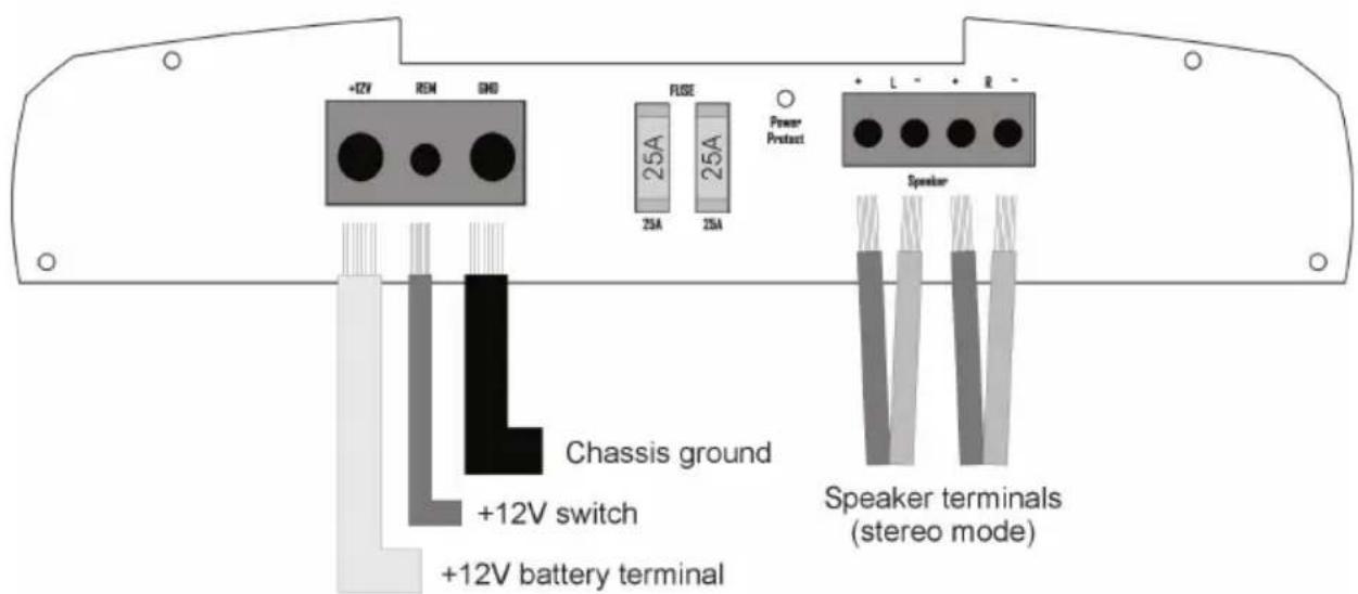
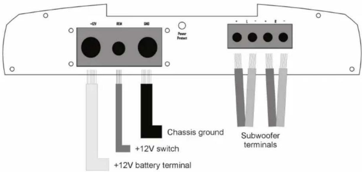
Using a minimum of 8 gauge wire, run a power cable directly to the positive terminal of your battery to the +12V terminal of your amp. A separate fuse must be located within 18 inches of the battery to protect the vehicle from a potential short. Total up the fuse ratings on your amplifiers to determine the fuse size required under the hood.
-
Your amplifier will turn on only when ignition is activated. This can be accomplished by connecting an 18 gauge wire to the 'trigger' output on your head unit. If you are using an OEM radio, this will not be available. You must locate a +12v switched circuit to achieve this.
-
The ground path is equally important to the positive feed of your amplifier. Find or create a bare metal spot on the vehicle's chassis. Using as short a wire as possible, connect to the 'GND' terminal using the same gauge wire as you did for power. The paint on the body must be removed to bare metal.
-
If you're using a low-level output signal from your head unit, ensure to use a high quality RCA cable to prevent unwanted noise. It is preferred to use the side opposite to the power wire to run the RCA. Failure to do so can introduce unwanted noise into the input signal which will be heard through your speakers.
-
If your head unit doesn't have RCA, then the hi-level input of the amp would be used. For this, it is ideal to tap in on the speakers closest to the amplifier location. Using regular 18 gauge speaker wire, take left and right (both positive and negative) signals. Connect directly to the 'hi-level' input on your amplifier. Proper gain settings are required to ensure undistorted sound.
-
You have now completed the basic installation portion of your new amplifier. Please continue to the "Amplifier Settings" section of this manual to properly configure your amp for maximum listening pleasure.
Amplifier Settings
The gain control (input sensitivity) on this amp is not a volume control. It is designed to provide proper matching of various source units to this amplifier, and provides a reference to how much signal will be necessary to reach maximum operating power. Correct settings will ensure safe operation for both your amplifier and speakers.
- Start by turning the gain level to the "8 volt" setting. This is the minimum level, far left.
- Next, turn up your head unit volume up to 75% of max volume. For example, if your digital volume control goes to "50", you would use the "40" level for this exercise.
- Last, slowly begin increasing the gain until distortion becomes audible, then turn the gain back a notch. You have now properly set your input sensitivity.
Crossover Control
Your amplifier has been designed with an onboard 18db/act crossover, or filter management system. How you configure these settings will be dependent on the speakers you are connecting to the amp. The crossover circuit consists of two main settings: 1. Filter Type; 2. Frequency Adjustment.
The "filter type" is controlled by a "LPF, FULL, HPF" switch. The low-pass filter, LPF, will allow only low frequency information to pass on to the speakers. The opposite would be achieved using the HPF, high pass filter. When no filter is required, the FULL setting would be selected, allowing all frequencies to pass.
For proper operation of some speakers, it is necessary to select the crossover point to which they will play. The "frequency adjustment" setting allows you to accomplish this. In a LPF mode, only frequencies up to the crossover point will play, with a gentle roll-off beyond that point. In HPF mode, any frequency above that point will be heard, with those below being filtered away gradually.
Bass Boost
Sometimes, we want a little more kick to our system's bottom end. Your amplifier has been outfitted with an internal circuit to provide a boost at frequencies surrounding 45hz. A bass boost should be treated similar to a gain control. Proper adjustment of this setting will be required to ensure safe operation of your amplifier and speakers. When boosting the lower frequencies, turning the input sensitivity down would be required. Failure to do so may result in permanent damage.
Remote Volume Control (sold separately)
Let's face it, bass levels can fluctuate considerably from one style of music to another. Having some control within reach enhances your level of listening pleasure. The RVC (not available on T3-2050), provides 18 steps of adjustment to fine tune your bass. Additionally, it provides essential monitoring of your amplifier. Should the amplifier begin to clip, the letter "C" will appear in the display and begin to flash. Continuous clipping will bring the "C" to a solid state. Clipping is the #1 reason for premature failure of your speakers or subwoofoers. If your voltage drops below 11v, the display will read "888". If the fuse should blow, the display will flash "...".
Ultimate
Subsonic Filter
Getting the most out of your amplifier is our goal. Having a subsonic filter in your subwoofer amplifier is going to achieve just that. If you're running a ported subwoofer system, it's crucial that the signal from your amplifier doesn't drop drastically below the tuning frequency. If that should happen, your subwoofer will feel as if it's in open air, and that the enclosure does not exist. The result, slow and permanent damage to the voice coil.
Our subsonic filter is always on to protect your subwooers. With a minimum setting of 20Hz , and selectable for 30 and 40Hz , your ensured that sub-harmonics are dropped off quickly. With most ports tuned in the 30 - 40Hz range, you can rest assured that your subwoofer will play cleaner and with less distortion. Furthermore, your amplifier runs more efficient by not wasting voltage and current on reproducing these frequencies.
Voltage and Temperature Monitor
Nothing is more critical to an amplifier than the power delivery system, and dissipating heat as quickly as possible. Your amplifier has been outfitted with circuitry to monitor both voltage and temperature through top-mount digital meters. Voltage is crucial in ensuring that a sufficient amount of current is reaching your amplifier. Having the proper gauge power wire and accessories will minimize your voltage loss. Using a high power capacitor will help maintain voltage levels during transient peaks in your music.
Amplifiers will generate heat, and heat is it's biggest enemy. Choosing a proper location for your amplifier will ensure that it gets the cooling required to operate at a safe temperature rating. It is not recommended to mount your amplifier upside down, in storage compartments or behind unventilated panels. Having the ability to monitor the temperature on your amplifier is a bonus!
Low Level Output
Many of today's car audio systems will run multiple amplifiers. Using a Y-adapter is not a preferred way to split your low level signal, as signal loss is guaranteed to happen. Your amplifier has been outfitted with a pre-amp output circuit to pass on a full-range signal on to your next amplifier. If you require fading capability between speakers, it will not be possible in this arrangement.
Trigger Output
Most head units today are outfitted with an amplifier "turn-on" circuit built in. Typically, the current capability of this circuit is 500mA . While sufficient to activate one or two amplifiers, anything more than that can require higher demands for current which it cannot handle. Our amplifiers have been outfitted with a turn-on circuit of it's own to assist you in your installation. Whether you're running multiple amplifiers, have additional processors or outboard processors, or use lighting effects in your installation, our +12v trigger will help you turn them on. This output is limited to 1A and is internally protected with auto-reset circuitry.
| Specifications | T3-2050 | T3-2100 | T3-4075 |
| Continuous Power: | |||
| ·4 ohms | 50x2 | 100x2 | 75x4 |
| ·2 ohms | 80x2 | 150x2 | 120x4 |
| Maximum Power: | |||
| ·4 ohms | 110x2 | 200x2 | 150x4 |
| ·2 ohms | 170x2 | 350x2 | 230x4 |
| Bridged Power: | |||
| ·4 ohms | 170x1 | 320x1 | 180x2 |
| THD: | 0.06% | 0.05% | 0.04% |
| Signal to Noise Ratio | 91db | 94db | 90db |
| Frequency Response: | 5-100Khz | 5-100Khz | 5-100Khz |
| Speaker Impedance: | 2 ohms | 2 ohms | 2 ohms |
| Damping Factor: | 250@4 ohms | 235@4 ohms | 205@4 ohms |
| Input Sensitivity: | 250mV - 8V | 250mV - 8V | 250mV - 8V |
| Dimensions: | 11" x 12 1/4" x 2 3/8" | 11" x 16" x 2 3/8" | 11" x 17" x 2 3/8" |
| 28cm x 31cm x 6cm | 28cm x 41cm x 6cm | 28cm x 44cm x 6cm | |
| Fuse Rating: | 30A | 25A x 2 | 40A x 2 |
| Max Current: | 11A | 22.5A | 33.5A |
| Specifications | T3-1250 | T3-500D | T3-1000D |
| Continuous Power: | |||
| ·4 ohms | 250x1 | 500x1 | 1000x1 |
| ·2 ohms | 320x1 | 900x1 | 1200x1 |
| Maximum Power: | |||
| ·4 ohms | 440x1 | 1000x1 | 1600x1 |
| ·2 ohms | 620x1 | 1800x1 | 3500x1 |
| Bridged Power: | |||
| ·4 ohms | |||
| THD: | 0.06% | 0.12% | 0.04% |
| Signal to Noise Ratio | 90db | 90db | 91db |
| Frequency Response: | 5-400 Hz | 5-400Khz | 5-400Khz |
| Speaker Impedance: | 2 ohms | 2 ohms | 2 ohms |
| Damping Factor: | 210@4 ohms | 230@4 ohms | 220@4 ohms |
| Input Sensitivity: | 250mV - 8V | 250mV - 8V | 250mV - 8V |
| Dimensions: | 11" x 16" x 2 3/8" | 11" x 19 3/4" x 2 3/8" | 11" x 23" x 2 3/8" |
| 28cm x 41cm x 6cm | 28cm x 50cm x 6cm | 28cm x 58cm x 6cm | |
| Fuse Rating: | 20A×2 | 40A×3 | External Only |
| Max Current: | 23A | 55A | 136A |
Ultimate
Introduction
Note: Ultimate recommends 8ga minimum to be used for optimum performance of this amplifier.
Diagram
T3-2100

Note: Ultimate recommends 4ga minimum to be used for optimum performance of this amplifier.

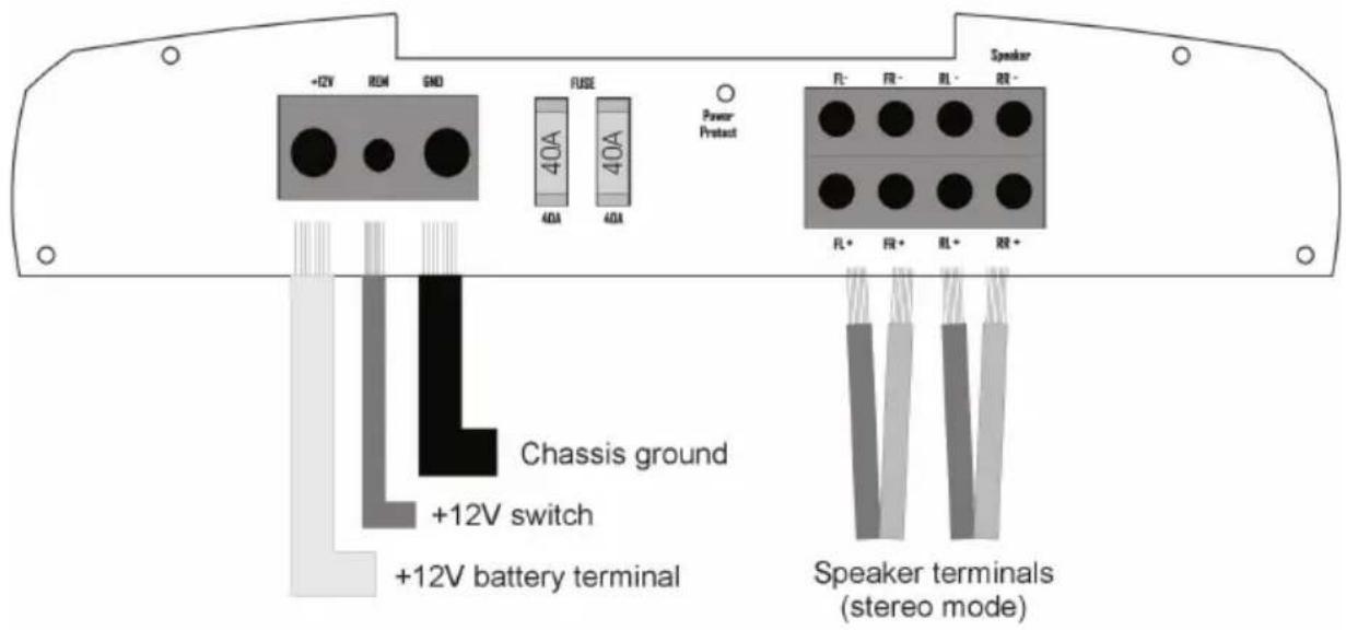
Note: Ultimate recommends 4ga minimum to be used for optimum performance of this amplifier.
Diagram
T3-1250
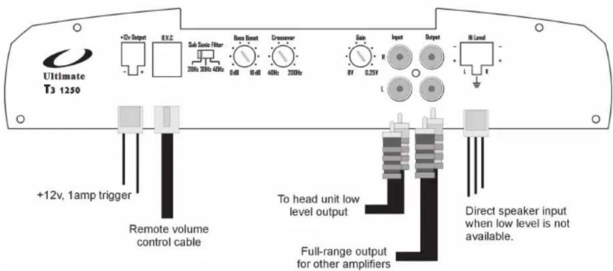
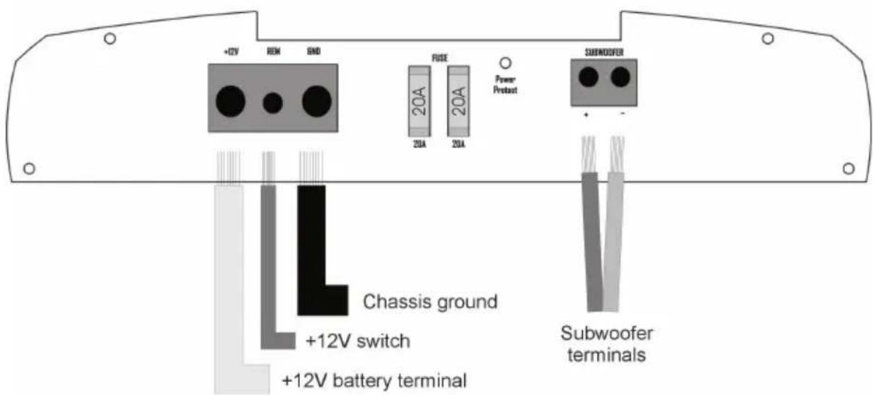
Note: Ultimate recommends 4ga minimum to be used for optimum performance of this amplifier.
Diagram
T3-500D
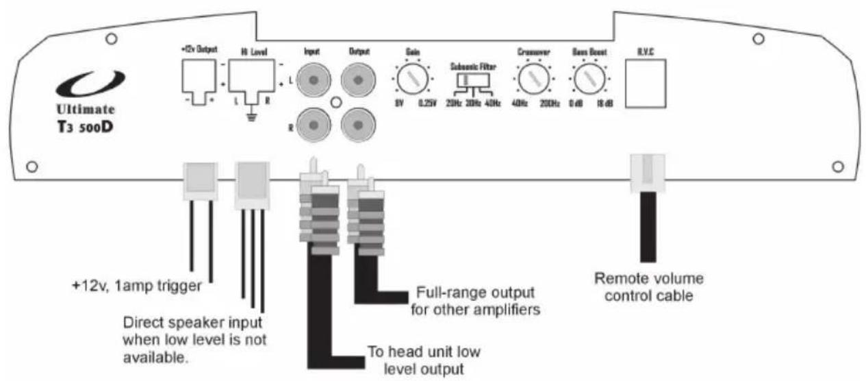

Note: Ultimate recommends 4ga minimum to be used for optimum performance of this amplifier.
Diagram
T3-1000D
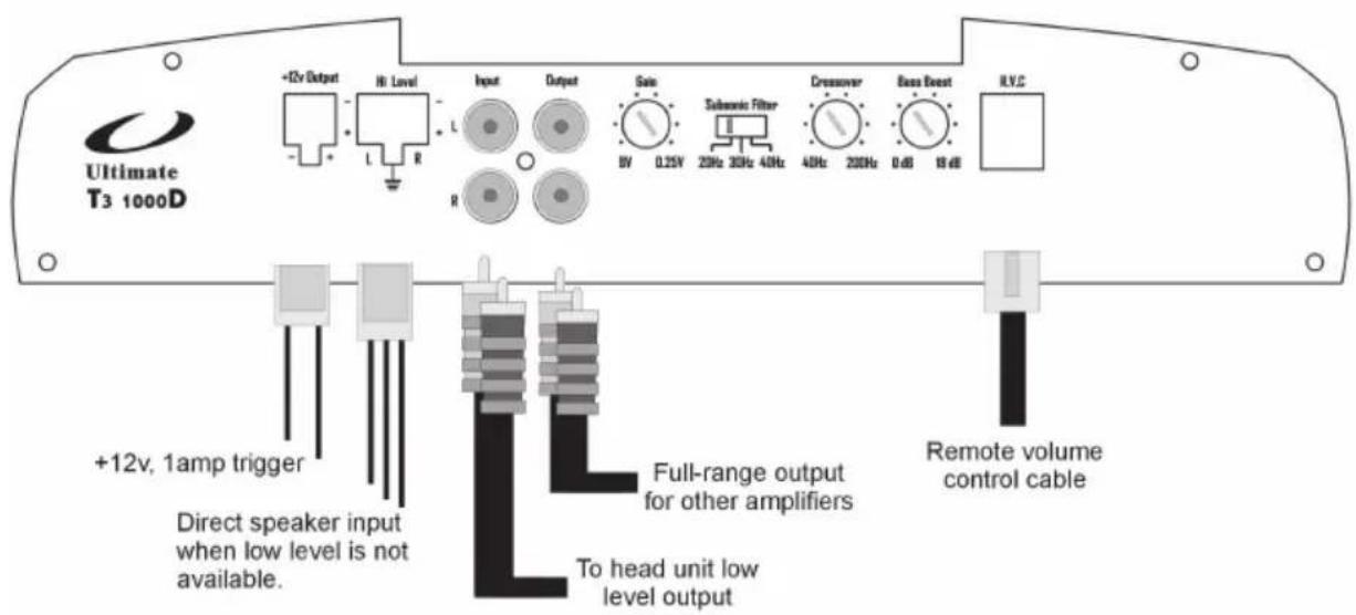
Note: Ultimate recommends 0ga minimum to be used for optimum performance of this amplifier. There is no fuse on this amplifier. An external, 150 amp fuse must be installed within 18 inches of the amplifier..
Notes / Notas / Anmerkungen
- Ultimate
- Introduction
- Caution
- Description
- Features
- Class AB - T3-2050, T3-2100, T3-4075, T3-1250
- Class D - T3-500D, T3-1000D
- Installation
- Amplifier Settings
- Crossover Control
- Bass Boost
- Remote Volume Control (sold separately)
- Subsonic Filter
- Voltage and Temperature Monitor
- Low Level Output
- Trigger Output
- Diagram
- T3-2100
- T3-1250
- T3-500D
- T3-1000D
- Notes / Notas / Anmerkungen
Brand : Ultimate
Model : T32100
Category : Car radio