
AMPLICALL 10 - Receiver GEEMARC - Free user manual and instructions
Find the device manual for free AMPLICALL 10 GEEMARC in PDF.
| Product Type | Telephone ring amplifier (receiver) |
| Brand | Geemarc |
| Model | AMPLICALL 10 |
| Dimensions (approx.) | 96 x 70 x 30 mm |
| Weight (approx.) | 200 g (with batteries) |
| Power Supply | 4 non-rechargeable AA batteries (included); optional mains adapter |
| Main Functions | Telephone ring amplification; selectable alarm (strobe flash, electronic ringer, vibrating pad); volume adjustment; 3 alarm tones |
| Mounting Type | Wall-mount (96 mm center distance) or tabletop (stand provided) |
| Number of Batteries | 4 AA batteries (1.5 V) |
| Battery Indicator | Flashing red LED for low battery |
| Compatibility | Hearing aids; FCC Part 68 standards |
| Included Accessories | RJ11 cord, table stand, 4 AA batteries |
| Optional Accessories | Mains adapter, vibrating pad, second AMPLICALL 10 |
| Maintenance | Test batteries once a year; replace when red LED flashes |
| Safety | Do not open or modify; avoid surges; unplug before replacing batteries |
| Warranty | 1 year parts and labor |
| Customer Service | Sonic ALERT: 1-888-864-2446 |
| Country of Compliance | United States (FCC); Canada (ACTA) |
| Ringer Equivalence Number (REN) | Check product label |
Frequently Asked Questions - AMPLICALL 10 GEEMARC
User questions about AMPLICALL 10 GEEMARC
0 question about this device. Answer the ones you know or ask your own.
Ask a new question about this device
Download the instructions for your Receiver in PDF format for free! Find your manual AMPLICALL 10 - GEEMARC and take your electronic device back in hand. On this page are published all the documents necessary for the use of your device. AMPLICALL 10 by GEEMARC.
USER MANUAL AMPLICALL 10 GEEMARC
Installation (See drawing)
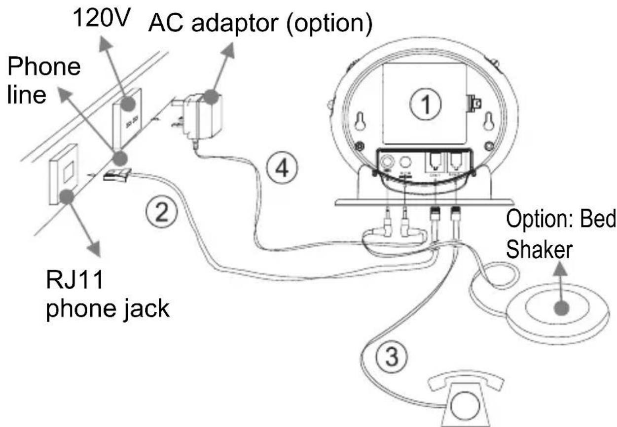
1) Insert 4 AA batteries into the battery compartment, for battery backup feature. Test batteries every year.
2) Connect the Phone cable to the line jack found at the rear of the Amplicall 10. Connect the other end of the cable to the on the wall.
3) Connect the telephone line cord from your telephone into the jack found at the rear of the Amplicall 10.
4) Plug the power cable into the power adapter jack found at the rear of the Amplicall 10. Plug the adaptor into the mains supply at the wall (optional)
INSTALLATION
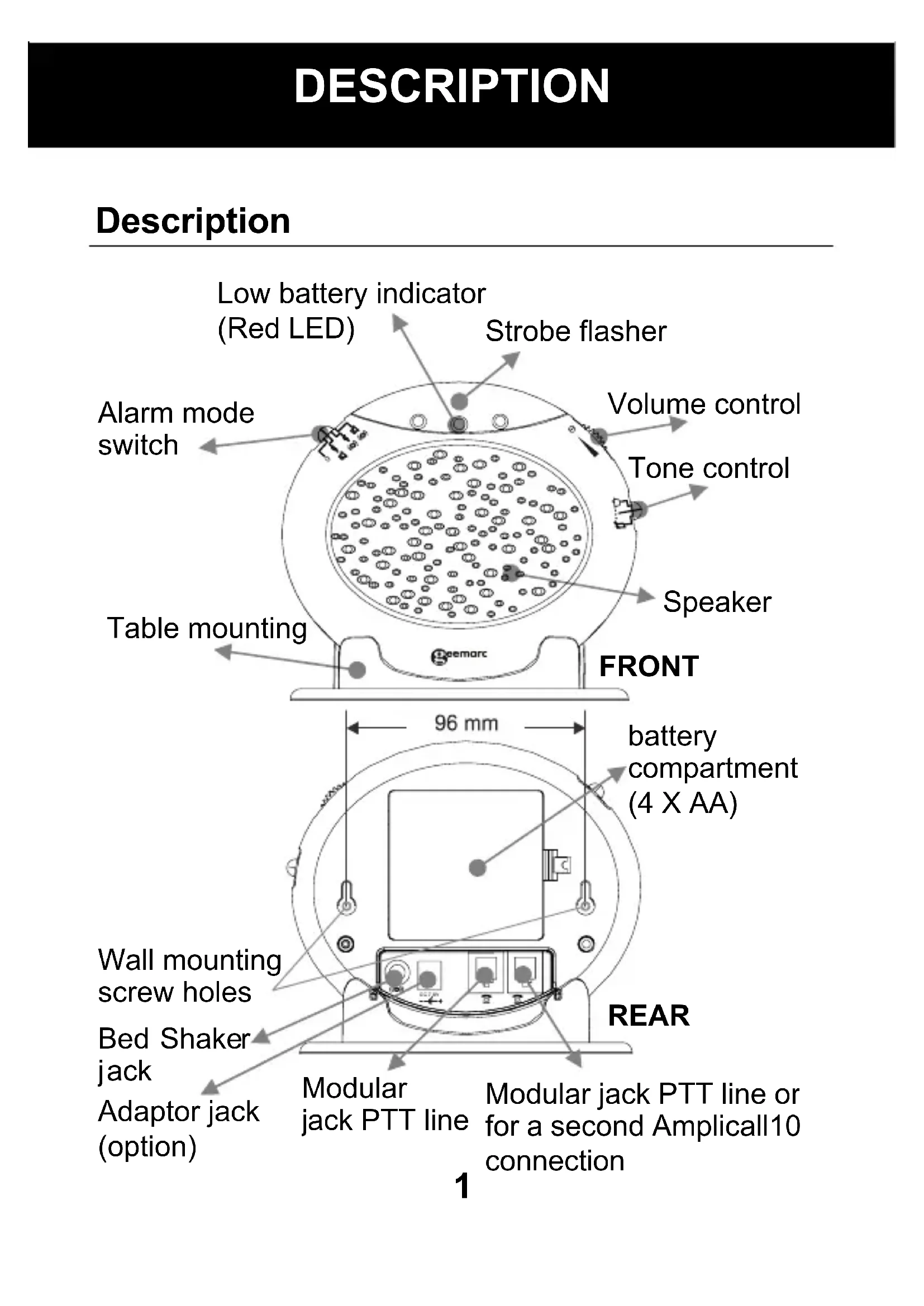
Alarm Operation
1 - SETTING THE ALARM MODE
Choose which alarm mode you want by moving the alarm mode switch to one of the following positions:
0 : no alarm
:both strobe flasher and sound alarm activated
: both strobe flasher and shaker (if connected)
(0) activated
: both sound alarm and shaker (if connected)
(0) activated
2 - VOLUME CONTROL SLIDE SWITCH
Set the volume of the alarm sound or power on/off.
3 - TONE CONTROL SWITCH (3 POSITIONS)
Set the tone of the alarm sound.
INSTALLATION
Wall Mounting
- Drill two holes horizontally, 96mm apart, and leave the screws protruding from the wall by 5mm.
- Hang the base on to the two screws and pull the base down to lock it into place.
Table Mounting
If you want to mount the unit on a table, simply place it in the base cradle, and place the base cradle on the table.
Change The Battery
The unit requires 4 × AA batteries
- Open the battery compartment door.
- Insert 4 x AA batteries into the battery compartment.
- Snap the battery compartment door back into place.
Note: when the red LED indicator flashes, it is time to replace the batteries.
When replacing the batteries, disconnect all telephone line cords from the modular wall jacks.
Second Amplicall 10
Another Amplicall 10 can be added to the system (call 1-888-864-2446). Add the second piece on one second PTT socket.
INSTALLATION
Trouble shooting
| Symptom | Solution |
| No incoming call yet the Amplicall10 rings automatically or rings continuously; the shaker vibrates automatically or continuously; the strobe LED flashes automatically. | 1) Check the batteries are inserted correctly. 2) Check the power adaptor is connected correctly. 3) Turn off the power switch for 10 minutes and then turn it on. |
| The red low battery LED flashes automatically. | 1) Replace the batteries. 2) Turn off the power switch for 10 minutes and then turn it on. |
| When there is an incoming call but no ringing can be heard. | 1) Check it is connected to the power adaptor correctly. 2) Check the batteries are installed correctly. 3) Check if the volume switch is switched on. 4) Check it is connected to the line cord correctly. |
INSTALLATION
When there is an incoming call but the shaker doesn't vibrate.
1) Check it is connected to the shaker correctly.
2) Check the shaker socket to see if it has been damaged.
3) Check the alarm mode selection switch position is correct.
REGULATORY COMPLIANCE
- This equipment complies with Part 68 of the FCC rules and the requirements adopted by the ACTA. On the bottom of this equipment is a label that contains, among other information, a product identifier in the format US:AAAEQ##TXXXX. If requested, this number must be provided to the telephone company.
- All applicable certification jacks Universal Service Order Codes (USOC) for the equipment is provided (i.e. RJ11C) in the package with each piece of approved terminal equipment.
- A plug and jack used to connect this equipment to the premises wiring and telephone network must comply with the applicable FCC Part 68 rules and requirement adopted by the ACTA. A compliant telephone cord and modular plug is provided with this product. It is designed to be connected to a compatible modular jack that is also compliant. See installation instructions for details.
- The REN is useful to determine the quantity of devices you may connect to your telephone line and still have all of those devices ring when your telephone number is called. In most, but not all areas, the sum of the REN's of all devices connected to one line should not exceed five (5.0). To be certain of the number of devices you may connect to your line, as determined by the REN, you should contact your local telephone company to determine the maximum REN for your calling area.
- If this equipment causes harm to the telephone network, the telephone company will notify you in advance that temporary discontinuance of service may be required.
REGULATORY COMPLIANCE
But if advance notice isn't practical, the telephone company will notify the customer as soon as possible. Also, you will be advised of your rights to file a complaint with the FCC if you believe it is necessary.
-
The telephone company may make changes in its facilities, equipment, operation or procedures that could affect the operation of the equipment. If this happens the telephone company will provide advance notice in order for you to make necessary modifications to maintain uninterrupted service.
-
This equipment may not be used on coin service provided by the telephone company. Connection to party lines is subject to state tariffs. This equipment is hearing aid compatible.
Warning: Changes or modifications to this unit not expressly approved by the party responsible for compliance could void the user's authority to operate the equipment.
NOTE : This equipment has been tested and found to comply with the limits for a Class B digital device, pursuant to Part 15 of the FCC Rules. These limits are designed to provide reasonable protection against harmful interference in a residential installation. Some cordless telephones operate at frequencies that may cause interference to nearby TV’s and VCR’s; to minimize or prevent such interference, the base of the cordless telephone should not be placed near or on top of a TV or VCR; and, if interference is experienced, moving the cordless telephone farther away from the TV
REGULATORY COMPLIANCE
or VCR will often reduce or eliminate the interference. However, there is no guarantee that interference will not occur in a particular installation. If this equipment does cause harmful interference to radio or television reception, which can be determined by turning the equipment off and on, the user is encouraged to try to correct the interference by one or more of the following measures:
- Reorient or relocate the receiving antenna.
- Increase the separation between the equipment and receiver.
- Connect the equipment into an outlet on a circuit different from that to which the receiver is connected.
-
Consult the dealer or an experienced radio TV technician for help.
-
If trouble is experienced with this equipment, for repair or warranty information, please contact our customer service staff at: 1-888-864-2446
If the equipment is causing harm to the telephone network, the telephone company may request that you disconnect the equipment until the problem is resolved.
- Please follow instructions for repairing if any; otherwise do not alter or repair any part of device except as specified.
Opening the equipment or any attempt to perform repairs will void the warranty. For service or repairs, call 1-888-864-2446.
REGULATORY COMPLIANCE
- Connection to party line service is subject to state tariffs. Contact the state public utility commission, public service commission or corporation for information.
- If your home has specially wired alarm equipment connected to the telephone line, ensure the installation of this telephone equipment does not disable your alarm equipment. If you have questions about what will disable alarm equipment, consult your telephone company or a qualified installer.
- This equipment is hearing aid compatible.
GARANTIE
Sonic Alert warrants the phone against any defect in materials or workmanship for the period of one year from the date of purchase.
Should you experience a problem, contact our customer service department. Be sure to save your sales receipt as proof of purchase date should you need warranty service.
Within a period of one year from purchase date, Sonic Alert will repair or replace (our discretion) your phone at no cost, if a defect in materials or workmanship is found. If we elect to replace your phone, we may replace it with a new or reconditioned product of the same or similar design.
Repair or replacement will be warranted for a period of 90 days or the original time on the original warranty, whichever is longer.
The warranty does not cover accidents, negligence or breakage to any parts. This includes shipping damage, failure to follow instructions, misuse, fire, floods, use of incompatible accessories, Acts of God or failure in your phone service carrier's line service. The product must not be tampered with or taken apart by anyone who is not an authorized Sonic Alert representative. Tampering with the phone will void ant written or implied warranties Sonic
Alert shall not be responsible for loss of time, inconvenience, property damage caused by your phone or any other accidental or consequential damages.
Warranty service is available only with proof of purchase.
GARANTIE
Simply send the Amplicall10(postpaid) and a copy of your sales slip as proof of purchase to:
Sonic Alert Warranty Center 1081 West Innovation Dr. Kearney, MO 64060
IMPORTANT : YOUR RECEIPT IS PART OF YOUR WARRANTY AND MUST BE RETAINED AND PRODUCED IN THE EVENT OF A WARRANTY CLAIM
SonicAlert
Sonic Alert Warranty Center
1081 West Innovation Dr.
Kearney, MO 64060
Sales: 248-577-5400 Fax: 248-577-5433
Customer Service & Warranty: 1-888-864-2446


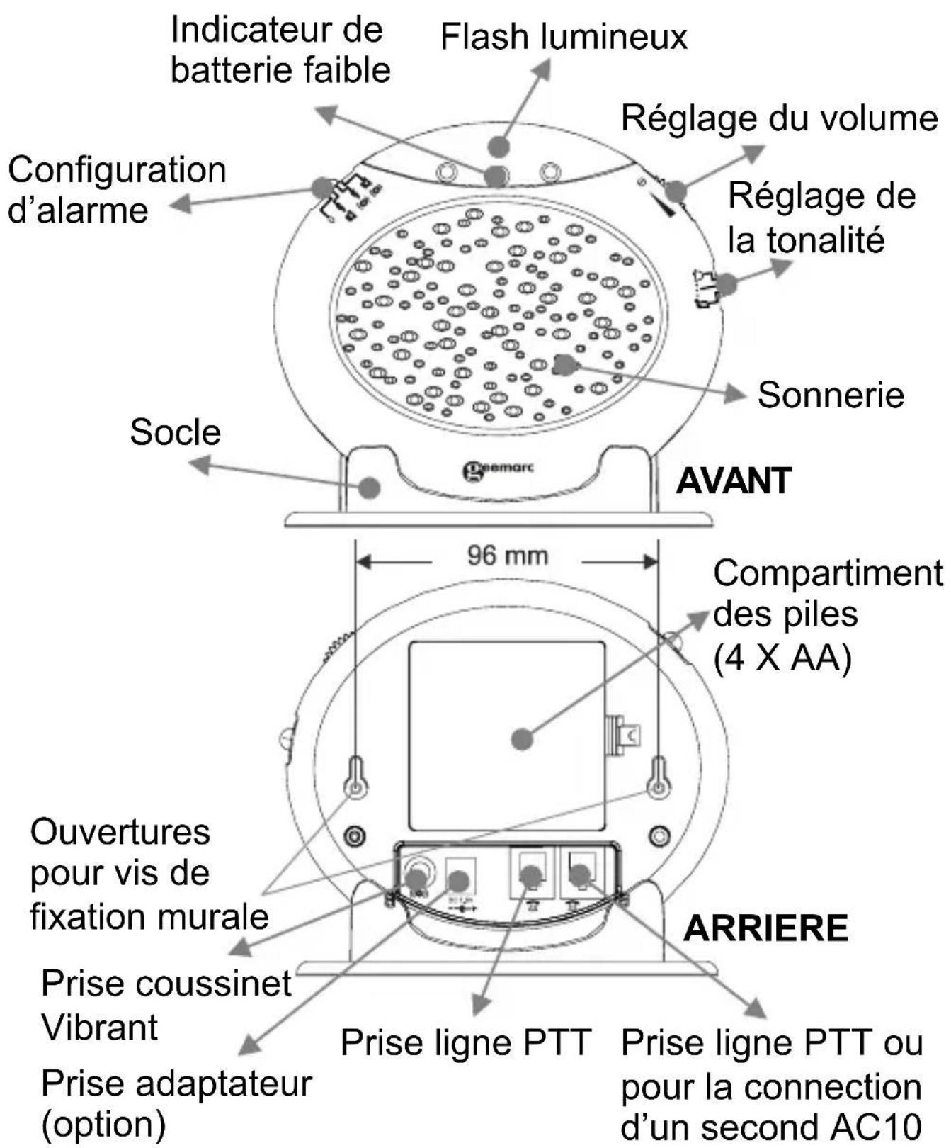
DESCRlPTIF
Descriptif
INSTALLATION
Sonic Alert Warranty Center 1081 West Innovation Dr. Kearney, MO 64060
SonicAlert
Sonic Alert Warranty Center
1081 West Innovation Dr.
Kearney, MO 64060
Sales: 248-577-5400 Fax: 248-577-5433
Customer Service & Warranty: 1-888-864-2446


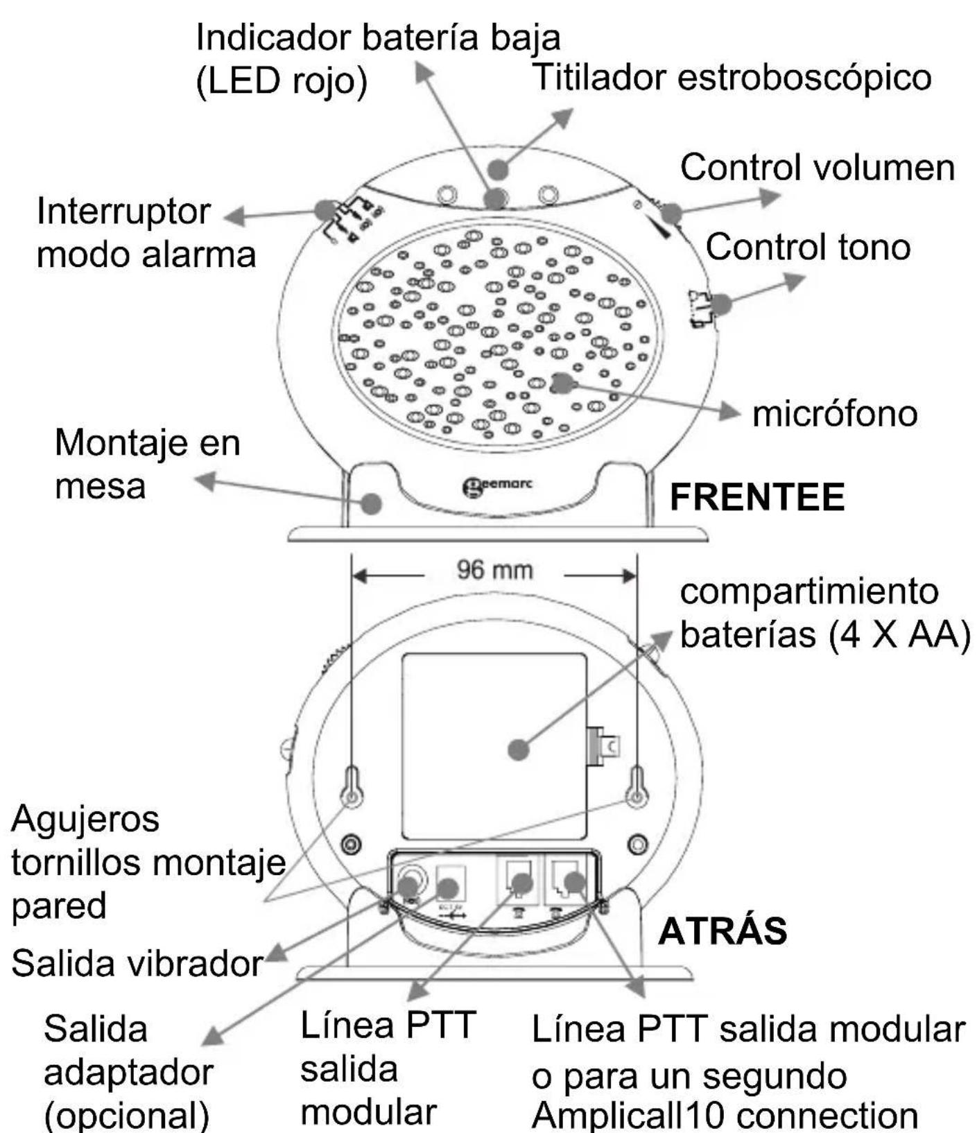
Descripción
Sonic Alert Warranty Center 1081 West Innovation Dr. Kearney, MO 64060
IMPORTANT: EL RECIBO FORMA PARTE DE LA
GARANTÍA Y DEBERÁ CONSERVARSE Y MOSTRARSE EN CASO DE EXISTIR UNA RECLAMACION DE GARAN'TÍA.
SonicAlert
Sonic Alert Warranty Center
1081 West Innovation Dr.
Kearney, MO 64060
Sales: 248-577-5400 Fax: 248-577-5433
Customer Service & Warranty: 1-888-864-2446


- Installation (See drawing)
- INSTALLATION
- Alarm Operation
- - SETTING THE ALARM MODE
- - VOLUME CONTROL SLIDE SWITCH
- - TONE CONTROL SWITCH (3 POSITIONS)
- Wall Mounting
- Table Mounting
- Change The Battery
- Second Amplicall 10
- Trouble shooting
- REGULATORY COMPLIANCE
- GARANTIE
- SonicAlert
- DESCRlPTIF
- Descriptif
- Descripción
Brand : GEEMARC
Model : AMPLICALL 10
Category : Receiver