
MTS3 - Monitor Marquant - Free user manual and instructions
Find the device manual for free MTS3 Marquant in PDF.

| Brand | Marquant |
| Model | MTS3 |
| Product type | Vehicle LCD monitor |
| Power supply | 11-14 V DC (car battery) |
| Power consumption | Not specified (estimated ~5-10 W) |
| Screen dimensions | Not specified (estimated 7-10 inches) |
| Weight | Not specified (estimated ~1 kg) |
| Screen resolution | Not specified (estimated 800x480 or higher) |
| Video inputs | 2 x AV (yellow RCA for video, red/white for audio) |
| Outputs | Headphone jack (3.5 mm) |
| Infrared receiver | Yes, with input for DVD player IR connector |
| Settings | Brightness, contrast, color, volume, 180° image flip |
| Integrated dome light | Yes, with 3-position switch (off, on with doors, continuous) |
| Mounting | Ceiling or stand (bracket included, screws) |
| Maintenance | Clean with a soft dry cloth, no harsh chemicals |
| Repairability | Replaceable bulb (unscrew old, insert new) |
| Safety | Do not use while driving, secure mounting required |
| Warranty | Warranty void if device opened |
| Included accessories | RCA cables, power cable, bracket, screws, user manual |
Frequently Asked Questions - MTS3 Marquant
User questions about MTS3 Marquant
0 question about this device. Answer the ones you know or ask your own.
Ask a new question about this device
Download the instructions for your Monitor in PDF format for free! Find your manual MTS3 - Marquant and take your electronic device back in hand. On this page are published all the documents necessary for the use of your device. MTS3 by Marquant.
USER MANUAL MTS3 Marquant
Desktop Installation
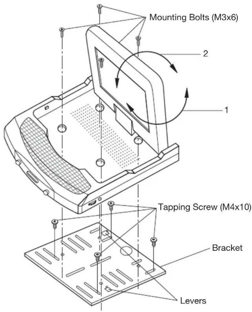
Fig. 1
-
Determine the mounting location and drill four mounting holes.
-
Attach the bracket to the holes with the tapping screws (M4x10).
-
Let the two levers aim at the fixing holes on the bottom of the base to fix the display unit.
-
Attach the TV unit to the preferred location with the mounting bolts (M3x6).
-
For the convenience of fixing the unit, you can turn the display left or right to show the holes on the base.
(See the arrowhead symbol named 1).
- When the installation has completed, you can turn the display upward or downward, left or right to adjust the viewing angle.
(See the arrowhead symbol named 2 and 1).
INSTALLATION
Ceiling-on Installation
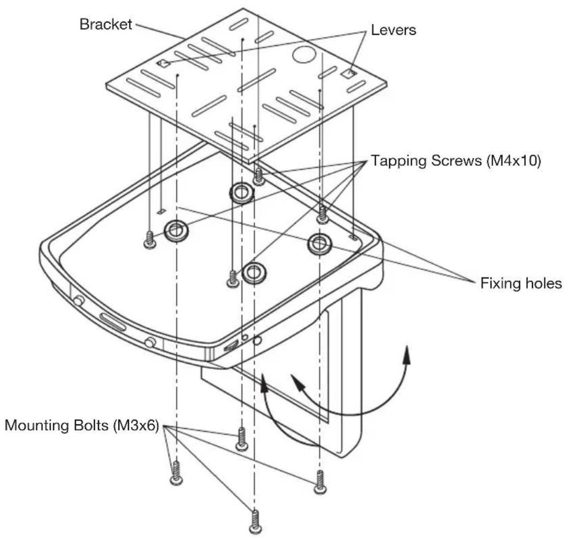
Fig. 2
- Determine the mounting location and drill four mounting holes.
- Attach the bracket to the holes with the tapping screws (M4x10).
- Let the two levers aim at the fixing holes to fix the display unit.
- Attach the unit to the bracket with the mounting bolts (M3x6).
- When the installation has completed, you can also turn the display upward or downward, left or right to adjust the viewing angle.
(See the arrowhead symbol).
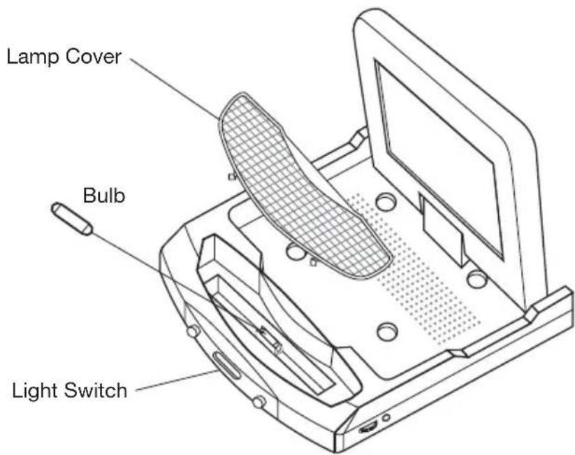
REPLACING THE CAR DOME LAMP
Follow the directions show below for a new lamp changing.
- Position light switch to " 量
- Push back the lamp cover and open it. (Refer to the following figure)
- Remove and discard the old lamp.
- Install a new bulb.
- Close the cover.
Bulb Specification
| Color | Connection |
| Red | Power Supply |
| White | Interior Light Supply |
| Black Ground | |
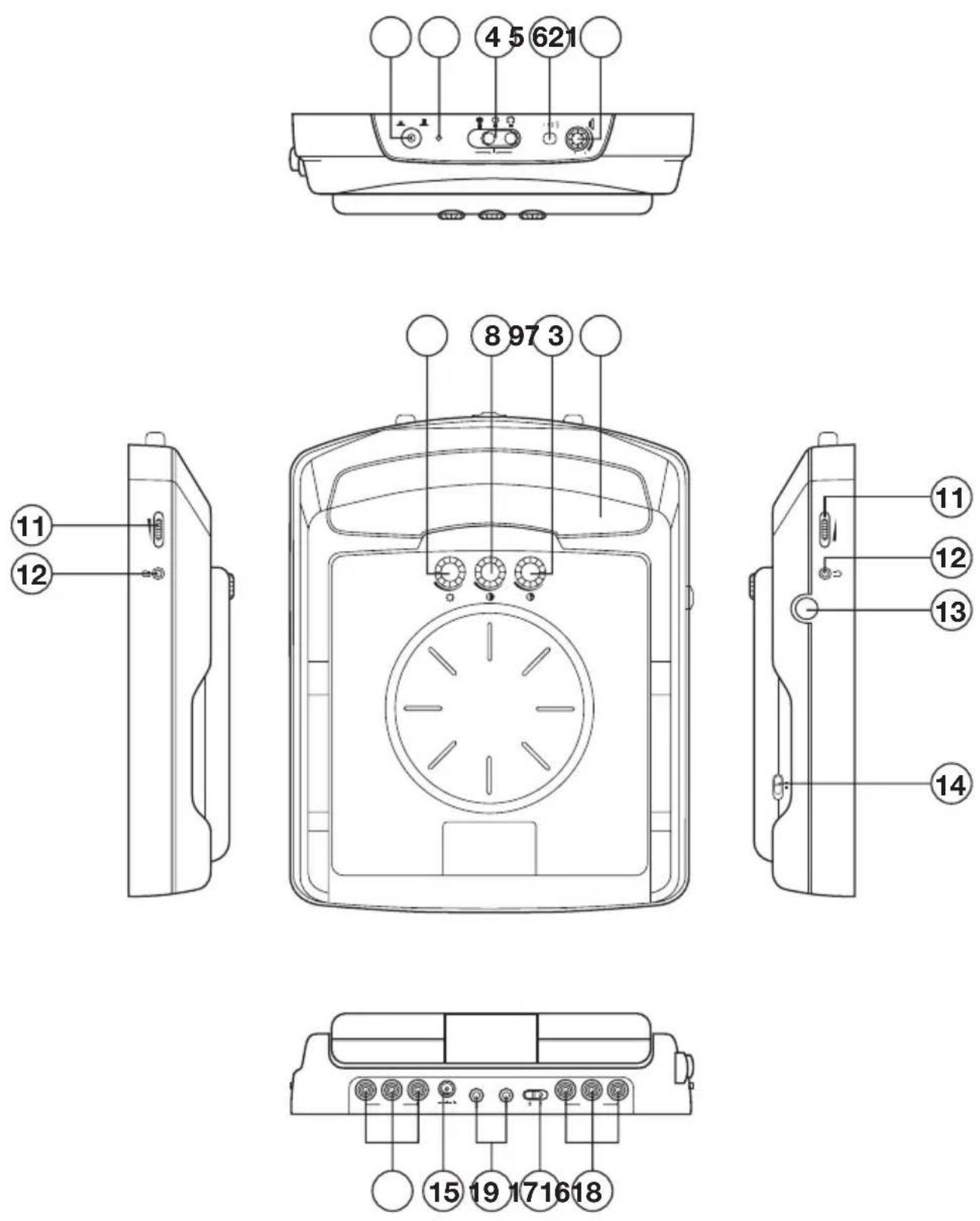
CONTROL & FUNCTION KEYS
CONTROL & FUNCTION KEYS
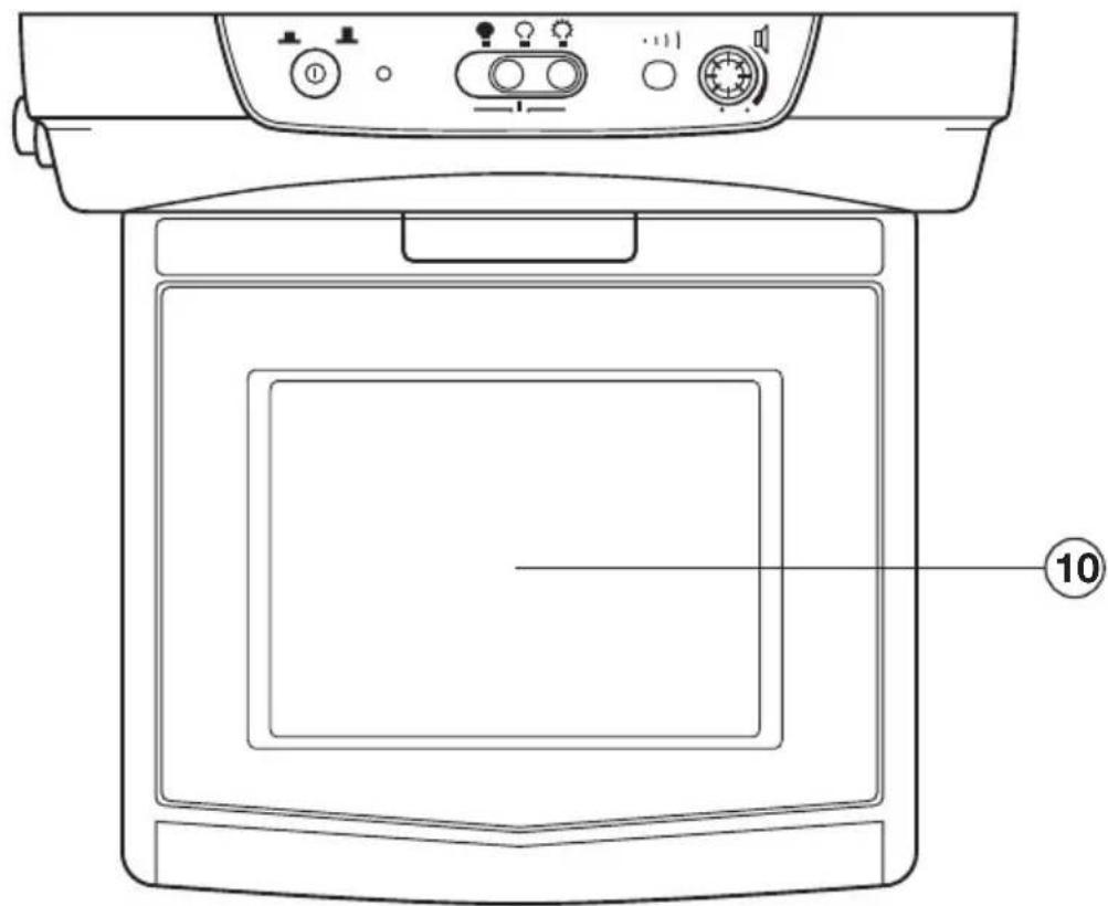
FIG.A
5.6 INCH TFT COLOR MONITOR
MONITOR
1. (F=POWER)
Press ① button (1) to turn on the unit. Press it again to turn it off.
2. POWER INDICATOR LIGHT
When the system is on, the indicator light (2) will be illuminated.
3. CAR DOME LAMP
The car dome lamp (3) will be on in some needed situations.
4. LIGHT SWITCH
The are three settings for the car dome lamp operation: (OFF), (AUTO), and ON, refer to light switch (4).
A.:To turn off the lamp.
B. :To make the lamp turned on only when car doors are opened.
C.:To turn on the lamp.
5. REMOTE SENSOR
Point the remote control handset to the remote sensor (5).
Press the function keys on the handset to control the unit, it would be worked for connecting the TV unit or DVD only.
6. SPEAKER VOLUME CONTROL KNOB
Rotate the knob (6) clockwise or counter-clockwise to increase or decrease the volume level of the speaker on the base of the unit. When rotate the knob in the direction of volume decreasing to the end, it will turn off the speakers.
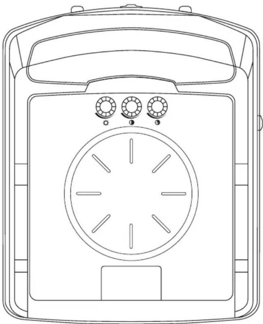
7.BRIGHT(
Rotate the bright knob (7) clockwise or counter-clockwise to increase or decrease the screen brightness.
8. CONTRAST (
Rotate the volume knob (8) clockwise or counter-clockwis to increase or decrease the contrast lever of the screen display.
9. COLOR (
Rotate the color knob (9) clockwise or counter-clockwis to increase or decrease the color lever of the screen display.
10. TFT LIQUID CRYSTAL DISPLAY
The 5.6 - inch color TFT LCD (10) can show the current state of the unit.
11. EARPHONE VOLUME CONTROL KNOB
Slide the knob (11) will change the volume of the earphone.
12. JACKS FOR EARPHONE
There are two jacks (12) for earphone. You can connect earphone to any one of the jacks to receive sound signal.
13. PUSH (Monitor Release Button)
Opening the Monitor
Press the PUSH button (13) to eject the screen display from the base at a little angle. Then you can easily turn the display upward or downward for good viewing. The monitor also can be adjusted through 30 degree both left and right from the central viewing position
Closing the Monitor
Return the monitor to the central viewing position. Then push the monitor back into the monitor base unit until the screen engages with PUSH button (13).
14. DISPLAY DIRECTION CONTROL SWITCH
The switch (14) should be dialed to DWN side or UP side to adjust the direction of the picture display and get user's needed viewing effect.
15. DC 12V INPUT
Through this jack (15), provide DC 12V power supply to the unit.
16. SENSOR
When connect DVD unit or another unit to the monitor through these two jacks (16), you can control the DVD unit or another unit by pointing the remote controll handset directly to the remote sensor (5).
17. AV1 IN
The group of jacks (17) is used for AUDIO R in anf AUDIO L in and VIDEO in.
18. AV2 IN
The group of jacks (18) is also used for AUDIO R in anf AUDIO L in and VIDEO in.
19. AV SELECT SWITCH
Slide the switch (19) to "1" side, the AV1 IN (17) group is available; slide the switch (19) to "2" side, AV2 IN (18) group is available.
GEBRUIKSAANWIJZING
CE
NEDERLANDS
WAARSCHUWING EN INFORMATIE

- Desktop Installation
- INSTALLATION
- Ceiling-on Installation
- REPLACING THE CAR DOME LAMP
- CONTROL & FUNCTION KEYS
- MONITOR
- (F=POWER)
- POWER INDICATOR LIGHT
- CAR DOME LAMP
- LIGHT SWITCH
- REMOTE SENSOR
- SPEAKER VOLUME CONTROL KNOB
- 7.BRIGHT(
- CONTRAST (
- COLOR (
- TFT LIQUID CRYSTAL DISPLAY
- EARPHONE VOLUME CONTROL KNOB
- JACKS FOR EARPHONE
- PUSH (Monitor Release Button)
- DISPLAY DIRECTION CONTROL SWITCH
- DC 12V INPUT
- SENSOR
- AV1 IN
- AV2 IN
- AV SELECT SWITCH
- GEBRUIKSAANWIJZING
- NEDERLANDS
- WAARSCHUWING EN INFORMATIE
Brand : Marquant
Model : MTS3
Category : Monitor