
C509 - Car radio Axton - Free user manual and instructions
Find the device manual for free C509 Axton in PDF.
| Product type | 4-channel amplifier |
| Brand | Axton |
| Model | C509 |
| RMS output power (4 ohms stereo) | 4 x 60 W |
| RMS output power (2 ohms stereo) | 4 x 90 W |
| RMS output power (4 ohms bridged) | 2 x 190 W |
| Frequency response | 10 - 30 000 Hz |
| Harmonic distortion (4 ohms) | < 0.05 % |
| Signal-to-noise ratio | > 95 dB |
| Channel separation | > 55 dB |
| Integrated filter slope | 12 dB/octave |
| Adjustable filter frequencies (HPF/LPF) | 40 - 240 Hz |
| Input sensitivity | 0.2 - 9 V |
| Input impedance | 47 kΩ |
| Damping factor (4 ohms) | > 250 |
| Power supply | 12 V (chassis ground) |
| Built-in fuses | 3 x 25 A |
| Recommended main fuse | 60 A |
| Dimensions (W x H x D) | 256 x 53 x 311 mm |
| Weight | Approximately 2.5 kg |
| Inputs | RCA low-level (2 pairs) |
| Speaker outputs | Binding posts (minimum impedance 2 ohms, 4 ohms bridged) |
| Protections | Overheating, short circuit, DC output |
Frequently Asked Questions - C509 Axton
User questions about C509 Axton
0 question about this device. Answer the ones you know or ask your own.
Ask a new question about this device
Download the instructions for your Car radio in PDF format for free! Find your manual C509 - Axton and take your electronic device back in hand. On this page are published all the documents necessary for the use of your device. C509 by Axton.
USER MANUAL C509 Axton
A General Features 24
B1 Connections & Controls C109 25/26
B2 Connections & Controls C209/C409 27/28
B3 Connections & Controls C509 29/30
C Amplifier Location & Mounting 31/32
D Wiring Tips. 31
E Connecting C109/C209/C409/C509 33
F Connecting Diagrams C109/C209/C409/C509 34-37
G Controls and Adjustments. 38-40
H Troubleshooting 41
Specifications 42
Warranty Certificate. 59/60
Index
Page
Introduction 43
ALLGEMEINE MERKMALE AXTON C109/C209/C409/C509
Thank you for purchasing this AXTON quality audio component.
The AXTON automotive amplifier series has been developed for the use with mobile sound systems using 12 Volts negative chassis ground power supply.
The amplifiers may be used in combination with almost any brand and type of head unit and speakers in cars, vans, boats etc. and when installed correctly, AXTON amps will produce exceptional sound results.
In order to familiarize yourself with all the special features and controlling options of your brandnew power amplifier, we advise you to read these instructions carefully before starting with the actual installation.
Should you have any difficulty in installing this amplifier in your vehicle, please contact your nearest AXTON dealer.
GENERAL FEATURES AXTON C109/C209/C409/C509
PWM MOSFET high efficiency switching power supply
A/B amplification technology with matched BJT transistors (Bipolar Junction Transistors)
Discrete solid state layout
7 Operating mode switchable between fullrange and highpass or lowpass amplification respectively
Integrated active high-/low pass filters with 12 dB/oct. cutting slope for satellite or subwoofer operation continuously adjustable from 40 - 240Hz
Soft start & turn-off delay circuit
Automatic on/off via remote switching from head unit
Protection circuitry against D.C. offset and short-circuits at speaker outputs as well as amplifier overload or overheat
Input level/gain adjustable from 0.2 to 9V
Connections & Controls
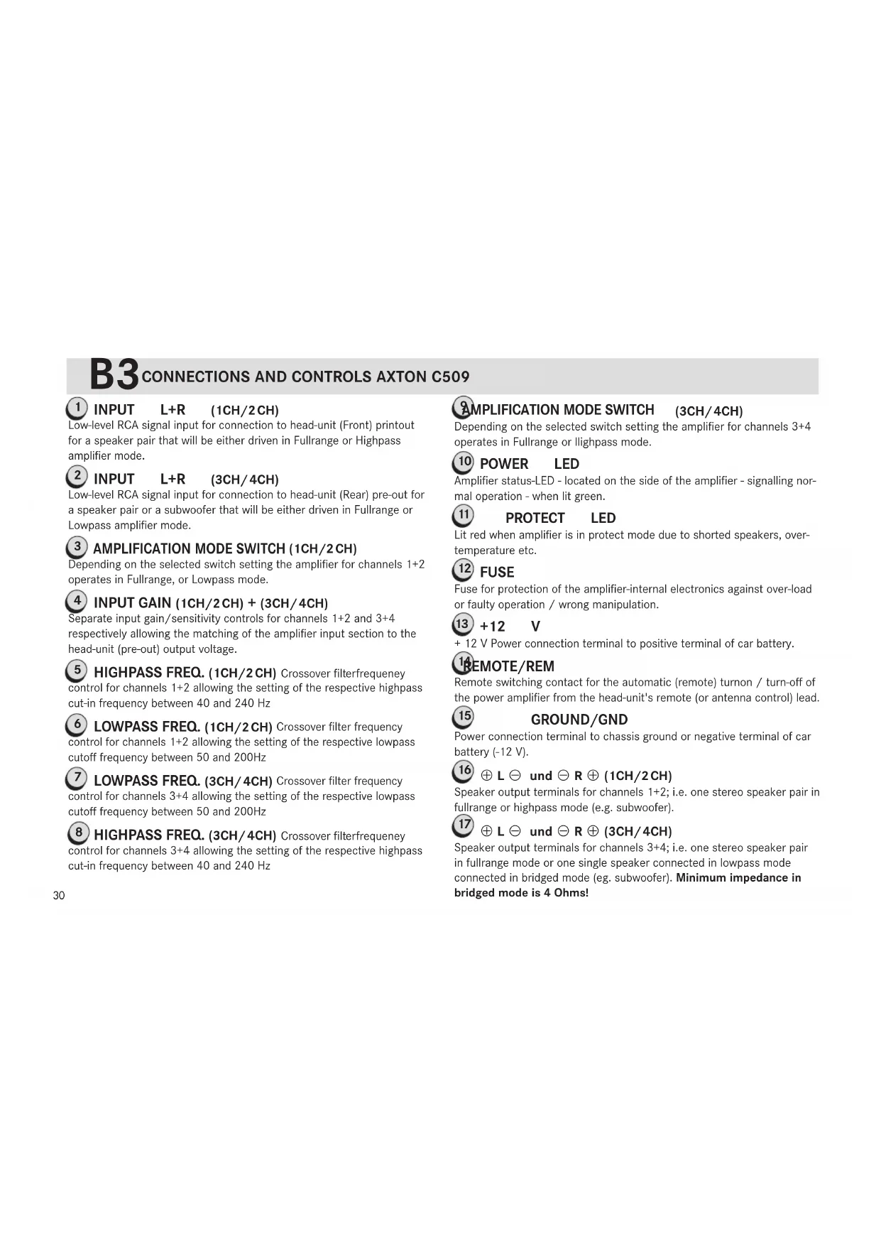
FRONT-PANEL AXTON C109
Connections & Controls
REAR-PANEL AXTON C109
B1 CONNECTIONS AND CONTROLS AXTON C109

INPUTL+R
Low-level RCA signal input for connection to head-unit pre-out.

INPUTGAIN
Input gain/sensitivity control allowing the matching of the amplifier input section to the head-unit (pre-out) output voltage.

FILTERFREQ.LPF
Crossover filter frequency control allowing the setting of the Lowpass cut-off frequency between 10 and 300Hz
Note: This control is not active when the amplification mode switch is in the "Fullrange" position!

AMPLIFICATION MODESWITCH
Depending on the selected switch setting the amplifier operates in Fullrange or Lowpass mode.

FILTERFREQ.SUBSONIC
Crossover frequency control allowing the setting of the Subsonic cut-in frequency between 10 and 60Hz

FUSE
Fuses for protection of the amplifier-internal electronics against overload or faulty operation / wrong manipulation.

+12V
Power connection terminal to positive terminal of car battery.

REMOTE/REM
Remote switching contact for the automatic (remote) turn-on / turn-off of the power amplifier from the head-unit's remote (or antenna control) lead.

GROUND/ND
Power connection terminal to chassis ground or negative terminal of car battery (-12 V)

L und R
Speaker output terminals for one or two subwoofer. The minimum speaker impedance is 2 Ohms!

POWERLED
Amplifier status-LED. Lit green when power is on.

PROTECTLED
Lit red when amplifier is in protect mode due to shorted speakers, overtemperature etc.

REMOITERPORT
Input for RJ11 jack, for the external bass level remote control.

OUTPUTL+R
Low level RCA signal output, to daisy-chain the RCA input signal to another amplifier.
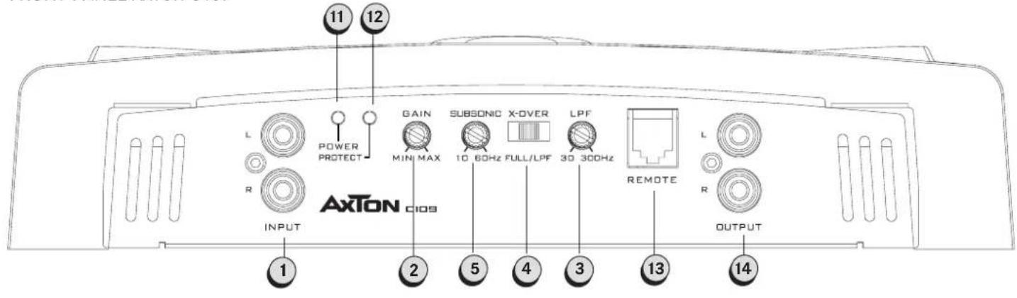
Connections & Controls FRONT-PANEL AXTON C209 and C409
Connections & Controls REAR-PANEL AXTON C209 and C409
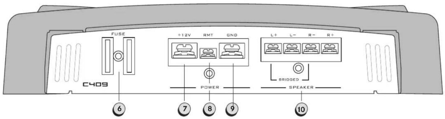
B2 CONNECTIONS AND CONTROLS AXTON C209/C409

INPUT
L+R
Low-level RCA signal input for connection to head-unit pre-out.

INPUT
GAIN
Input gain/sensitivity control allowing the matching of the amplifier input section to the head-unit (pre-out) output voltage.

LTER FREQ. LPF
Crossover filter frequency control allowing the setting of the Lowpass cut-off frequency between 40 and 240Hz
Note: This control is not active when the amplification mode switch is in the "Fullrange" position!

Implification Mode Switch
Depending on the selected switch setting the amplifier operates in Fullrange, Highpass or Lowpass mode.

LTER FREQ. HPF
Crossover filter frequency control allowing the setting of the Highpass cut-in frequency between 40 and 240Hz
Note: This control is not active when the amplification mode switch is in the "Fullrange" position!

FUSE
Fuses for protection of the amplifier-internal electronics against overload or faulty operation / wrong manipulation.

+12
V
Power connection terminal to positive terminal of car battery.

REMOTE/REM
Remote switching contact for the automatic (remote) turn-on / turn-off of the power amplifier from the head-unit's remote (or antenna control) lead.

GROUND/GND
Power connection terminal to chassis ground or negative terminal of car battery (-12 V)

unc
R
Speaker output terminals for one stereo speaker pair or one single speaker connected in bridged mode (e.g. subwoofer) In bridged mode the minimum speaker impedance is 4 Ohms!

POWER
LED
Amplifier status-LED. Lit green when power is on.

PROTECT
LED
Lit red when amplifier is in protect mode due to shorted speakers, overtemperature etc.
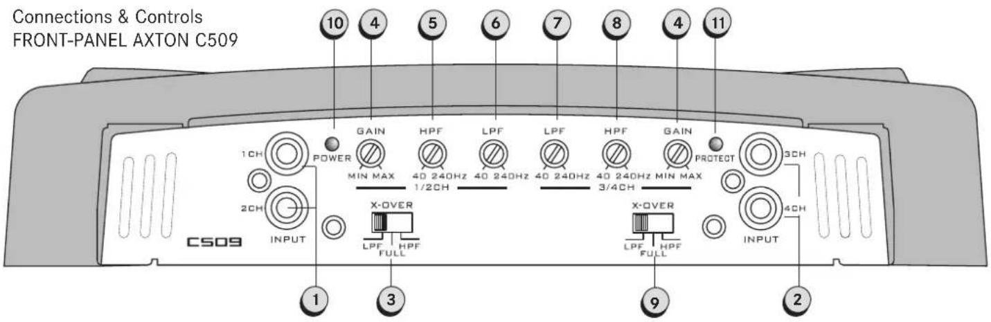
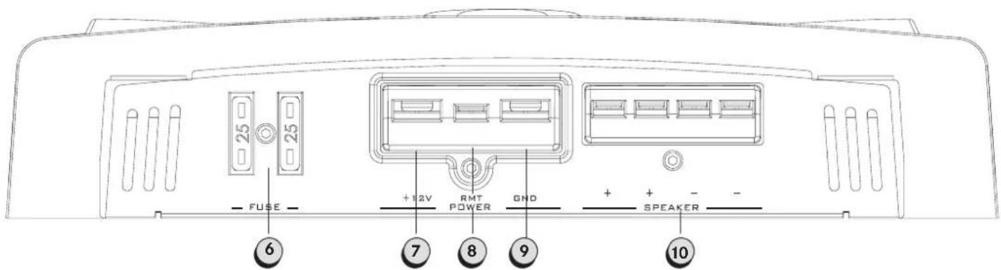
B3
CONNECTIONS AND CONTROLS AXTON C509
1 INPUT L+R (1CH/2CH)
Low-level RCA signal input for connection to head-unit (Front) printout for a speaker pair that will be either driven in Fullrange or Highpass amplifier mode.
2 INPUT L+R (3CH/4CH)
Low-level RCA signal input for connection to head-unit (Rear) pre-out for a speaker pair or a subwoofer that will be either driven in Fullrange or Lowpass amplifier mode.
3 AMPLIFICATION MODE SWITCH (1CH/2CH)
Depending on the selected switch setting the amplifier for channels 1 + 2 operates in Fullrange, or Lowpass mode.
4 INPUT GAIN (1CH/2CH) + (3CH/4CH)
Separate input gain/sensitivity controls for channels 1 + 2 and 3 + 4 respectively allowing the matching of the amplifier input section to the head-unit (pre-out) output voltage.
5 HIGHPASS FREQ. (1CH/2 CH) Crossover filterfrequency control for channels 1 + 2 allowing the setting of the respective highpass cut-in frequency between 40 and 240Hz
LOWPASS FREQ. (1CH/2CH) Crossover filter frequency control for channels 1 + 2 allowing the setting of the respective lowpass cutoff frequency between 50 and 200Hz
LOWPASS FREQ. (3CH/4CH) Crossover filter frequency control for channels 3 + 4 allowing the setting of the respective lowpass cutoff frequency between 50 and 200Hz
8 HIGHPASS FREQ. (3CH/4CH) Crossover filterfrequency control for channels 3 + 4 allowing the setting of the respective highpass cut-in frequency between 40 and 240Hz
AMPLIFICATION MODE SWITCH (3CH/4CH)
Depending on the selected switch setting the amplifier for channels 3 + 4 operates in Fullrange or llighpass mode.
10 POWER LED
Amplifier status-LED - located on the side of the amplifier - signalling normal operation - when lit green.
11 PROTECT LED
Lit red when amplifier is in protect mode due to shorted speakers, over-temperature etc.
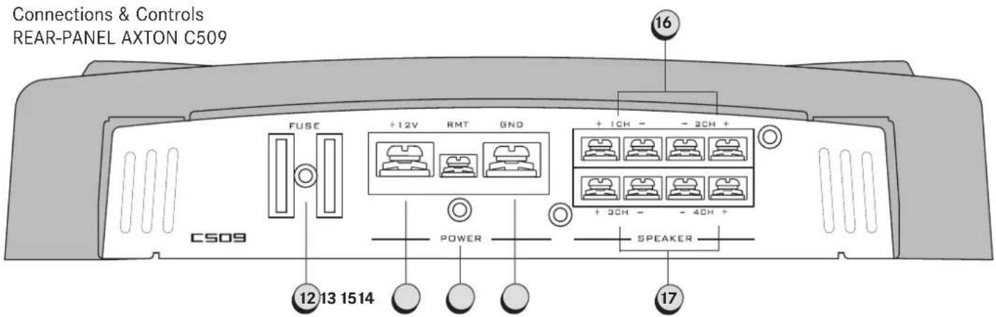
12 FUSE
Fuse for protection of the amplifier-internal electronics against over-load or faulty operation / wrong manipulation.
13 +12 V
+12 V Power connection terminal to positive terminal of car battery.
16 REMOTE/REM
Remote switching contact for the automatic (remote) turnon / turn-off of the power amplifier from the head-unit's remote (or antenna control) lead.
15 GROUND/GND
Power connection terminal to chassis ground or negative terminal of car battery (-12V)
Speaker output terminals for channels 1+2; i.e. one stereo speaker pair in fullrange or highpass mode (e.g. subwoofer).
17 L und R (3CH/4CH)
Speaker output terminals for channels 3 + 4 i.e. one stereo speaker pair in fullrange mode or one single speaker connected in lowpass mode connected in bridged mode (eg. subwoofer). Minimum impedance in bridged mode is 4 Ohms!

AMPLIFIER LOCATION & MOUNTING
1 The mounting location of the power amplifier will have a large effect both on its ability to dissipate the heat generated during normal operation through the heat sink and on the possible triggering of its internal overheat protection shut-off circuit. Any mounting position allowing for a good air stream across the cooling fins of the amplifiers heatsink will improve cooling and long-term stability dramatically.
With the AXTON amplifier series the most efficient ventilation is achieved when the units are installed standing up!
Therefore select a suitable location that is convenient for mounting and accessible for wiring and offers sufficient ventilation for cooling. As your amplifier features no controls for normal operation, it may be mounted away from the dashboard, i.e. under a car seat or in the trunk. However, make sure the unit is not exposed to excessive dust, direct sunlight, humidity, water, oil or other fluids that may enter the amplifier.
The amplifier should be mounted to a solid surface that will ensure a vibration-free mount. Once the location is selected, use the unit as a template for the marking of the mounting holes which should also be pilot-drilled before mounting of the amp is carried out.
3 Secure the amplifier using the four screws. Avoid to let the amplifier get into contact with metal parts of the vehicle. This helps to prevent unwanted ground loops.

WIRING TIPS
Please note: wrong power or signal connections may damage the amplifier and other components connected to it. Therefore, please read this manual carefully before the connection of any power, signal and speaker leads is done.
The wire routing is critical for noise-free performance. For best results, please follow the general wiring guidelines listed below (for details see section B, E, F and G of this manual).
1 For audio signal connections you should always use double or triple shielded quality RCA cables.
2 Signal, speaker and power cables should always be kept as short as possible:
Speaker and power cables may be cut to fit the actual length required.
Shielded RCA/signal cables should never be cut and replicated, as they will loose their protective shielding effect at those points where they have been cut. If the signal cable is too long, make an S-type loop (never a coil loop) in the centre of the cable to take-up the excess length.
3 Never route any low level/signal cable near or parallel to speaker outputs/speaker cables, amplifier power cables or high energy ignition wires.
Use power cable with the recommended cross section (see section E). Small cross sections are reducing the output power, are causing distortions and may be triggering the overheat protection of the amplifier.
5 Make sure you are using a main fuse protection for the +12V power input of the amplifier within max. 30 cm of the car battery and power cables with an amperage adequate cross-section and main fuse (for details see section E: „Connecting").
6 The GROUND/GND cable (-12V) should have the same cross-section as the +12V power cable. Make sure to get a good chassis ground contact, because poor ground contacts are the cause for most power problems with car audio installations.
7 Make sure no power, signal or speaker lines are shorting to chassis ground by using rubber grommets wherever a cable has to pass through any metal part of the vehicle.
Important: Before any wiring, always remove the +12V terminal of the battery to prevent short-circuiting. The last lead to be connected in every installation is always the positive +12 Volt terminal of the battery. Connect this lead only after having completed and checked all other connections.

CONNECTING
IMPORTANT: DISCONNECT THE +12V MAIN POWER CABLE FROM YOUR CAR BATTERY BEFORE ANY CONNECTING WORK IS CARRIED OUT!
| Recommended Power Cable Cross-Sections and Main Fuse Values (for +12V and Ground cable based on 5m +12 V cable) | |||
| Model | Cross-Section | Main | Fuse |
| C109 | 20 mm² | 60 A | |
| C209 | 8-20 mm² | 30-40 | |
| C409 | 20 mm² | 60 | |
| C509 | 20 mm² | 60 A | |
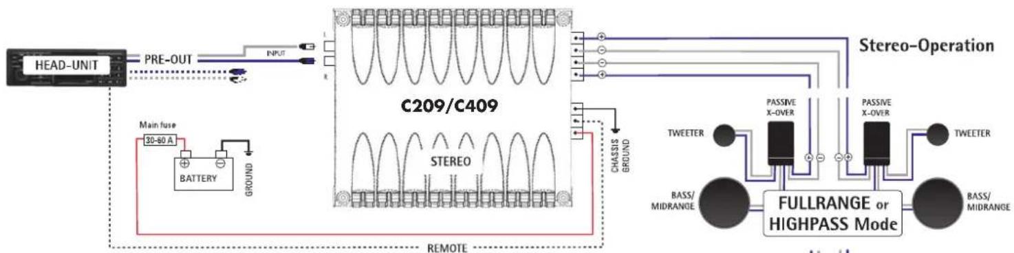
It is recommended to connect your amplifier in the following sequence:
1 Make sure your head-unit is turned off and the volume control is in its minimum position.
2 RCA outputs of your head-unit to respective RCA inputs of your amplifier (see „Connecting Diagrams").
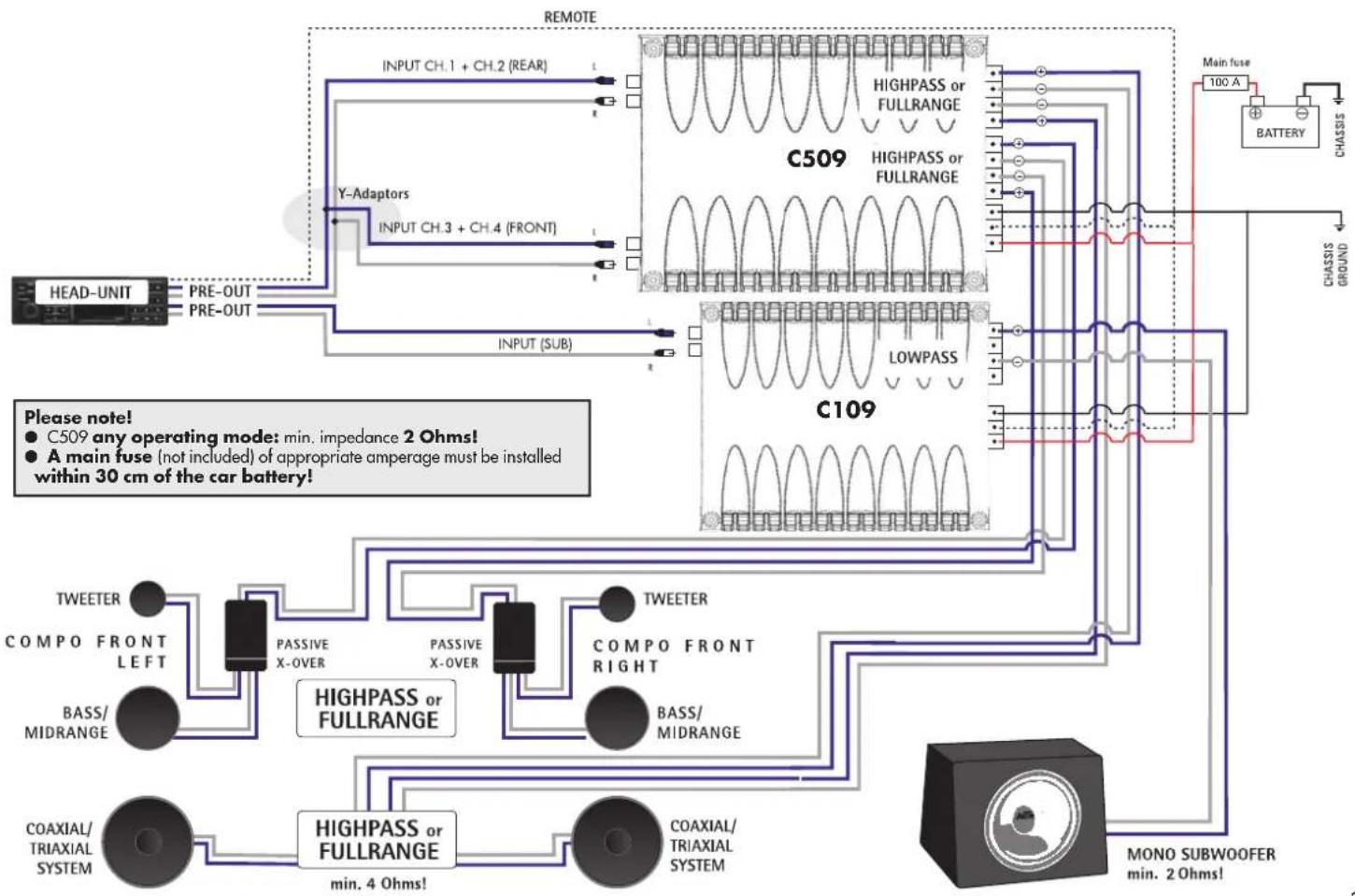
Sub pre-outs from head-unit should be fullrange signals because lowpass pre-out signals always affect the filtering electronics of amplifier! In case of doubt just 'double' a fullrange front or rear pre-out by using Y-adaptors.
Remote lead connection from head-unit to amplifier.
C109/C209/C409/C509
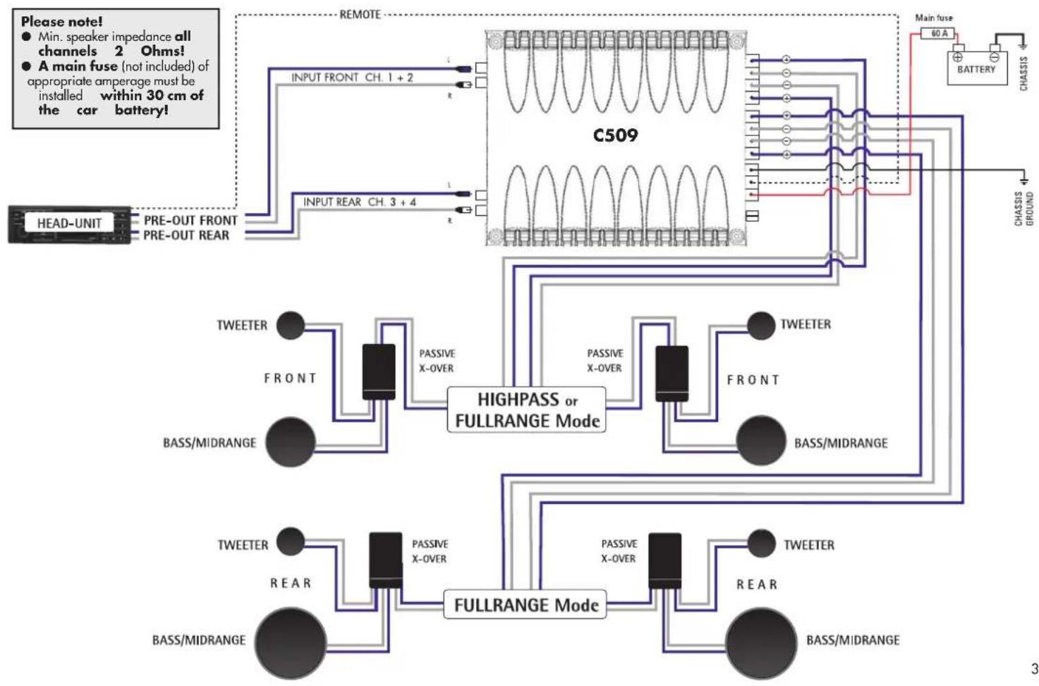
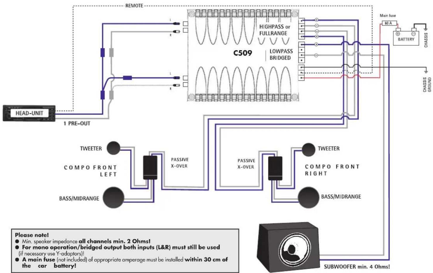
4 Speaker cables to respective speakers or passive crossovers. Make sure to maintain polarity! "⊕" to "⊕" and "Θ" to "Θ".
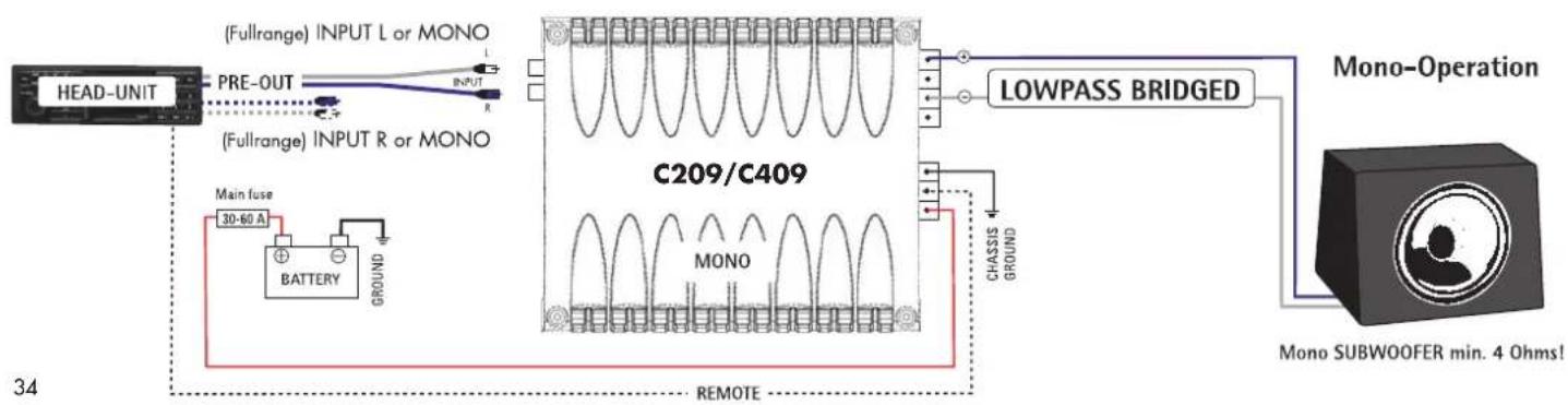
For Mono 1-channel mode use of 4 / 2 -channel models, connect the two terminals and marked with BRIDGE!
Min. impedance for bridged mode is 4 Ohms!
Ground connection to chassis ground or -12 V negative battery pole. If possible keep ground cable as short as possible and make sure the chassis contact is well sand-papered, i.e. clean from any paint, rust or dirt for maximum contact.
A
+12 V power connecteonto positive battery pole. Do not forget to install a main fuse within 30 cm of car battery (fire hazard)!!!
Do not connect +12V cable to battery before re-checking every other connection on the amplifier!
Turn-on your head-unit keeping your volume at the lowest setting. The green status LED on front of the amplifier heat sink should light up now. If not, turn-off your head-unit and re-check all wiring to and from the amplifier for missing or faulty connections.
Please note!
- The AXTON C209 and C409 amplifier models may be used in FULLRANGE, HIGHPASS or LOWPASS mode.
In stereo operation speaker impedance may be 2-4 Ohms.
In bridged mono operation minimum speaker impedance is 4 Ohms.
For mono operation/bridged output both inputs (L&R) must still be used (if necessary use Y-adaptors)!
A main fuse (not included) of appropriate amperage must be installed within 30 cm of the car battery!
CONNECTING DIAGRAM 3 C509
2 Pre-Out 4-Channel Operation
CONNECTING DIAGRAM 4 C509
1 Pre-Out 3-Channel Operation

CONTROLS & ADJUSTMENTS
Sequence of Adjustments
Depending on amplifier type (mono, 2-channel, 4-channel or a combination thereof), amplification mode (fullrange, highpass or lowpass) and connecting mode (stereo or mono bridged) it is possible, that only part of the adjustments described in this manual section are applicable to your individual car audio system.
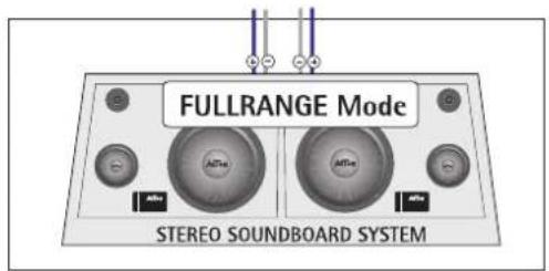
If you are using your amplifier in conventional fullrange mode (eg. with a soundboard), you may skip paragraph "1. Crossover Frequency Settings" and go directly to "2. Sensitivity Adjustments".
In case you are using your new amplifier(s) in a multi-channel amplifier system with highpass-filtered front and/or rear satellites and/or a lowpass-filtered subwoofer, we recommend you to read the complete section "Controls & Adjustments" before you start adjusting any of the frequency or level controls.
However, it is recommended to keep to the practical and logical sequence of the frequency and level adjustments as described in this manual section.
Active Highpass and Lowpass Filtering
The AXTON models C109, C209, C409 and C509 do not only offer conventional fullrange amplification: You also have the choice of high-pass or lowpass amplification mode, enabling you to drive your car audio speakers in the specific frequency range where they will perform best.
In HIGHPASS mode dashboard, door and rear shelf speakers (usually between 10 and 16cm diameter) - which do not give you strong bass
reproduction anyway - will only be playing in the midbass and mid/high frequency range. This so-called highpass filtered or HPF amplification mode also puts less electrical and mechanical 'strain' on your coaxials and component speaker systems, resulting in an increased power-handling capacity.
In LOWPASS mode the respective speaker output will only receive low-pass filtered (LPF) signals resulting in the subwoofer only playing in the low-end bass frequency range without any unwanted 'smearing' into the mid/high frequencies.
1 CROSSOVER FREQUENCY SETTINGS (FILTER) FREQ. HIGHPASS & LOWPASS
Before you can effect the respective input sensitivity / gain adjustments (LEVEL) you first have to select the system appropriate crossover frequencies for all speakers connected by way of the respective filtering controls marked FILTER FREQ. or SUBSONIC, HIGHPASS and LOWPASS FREQ. (depending on amplifier model). For best results all crossover settings should usually be played by ear rather than by guessing a frequency value!
Do not forget to set the amplification mode switches into the required position, i.e. HIGHPASS or LOWPASS! Any frequency setting on the filtering controls will be inactive if the amplification mode switch remains in position FULL!
For appropriate crossover frequency selection, all tone controls (Bass, Mid, Treble, Sub) and all fader and balance controls etc. on the head unit have to be brought to their neutral or center position!
The "Loudness" function should also be deactivated.
The HIGHPASS filtering setting (HPF) - on the respective (FILTER) FREQ. control - of the satellite channels will also take away unnecessary mechanical and electrical 'strain' from coaxial speakers or component speaker systems (compos), as such speakers are not designed to reproduce powerful bass signals in the first place. Depending on the actual cone surface area, voice-coil diameter and the rated power handling of the 'satellites' it is recommended to set the hiphpass cross-over / cut-in frequency between 40 and 240Hz .
If the satellite highpass frequency is set too low, the mid-bass reproduction will be increased, but at the same time the power-handling capacity of the satellites will decrease. If the highpass frequency is set too high, the mid-bass reproduction will become 'thinner' while the power-handling capacity of the satellites will increase.
As a general guideline, below you find a practice-proven list for appropriate satellite (HIGHPASS) FREQ. / HPF crossover frequencies covering the most widely used dashboard, door and rear-shelf speaker diameters:
Front Satellite Systems HPF (FILTER) FREQ.
10 cm Coaxials or 2-Way Compos 90-120 Hz
13 cm Coaxials or 2-Way Compos 80-100 Hz
16 cm Coaxials or 2/3-Way Compos 70 - 80 Hz
Heck Satellite Systems HPF (FILTER) FREQ.
10 cm Coaxials or 2-Way Compos 100-150 Hz
13 cm Coaxials or 2-Way Compos 120-130 Hz
16 cm Coaxials or 2/3-Way Compos 100-130 Hz
Satellite rule 1 The better sounding satellite system should always be installed in the front of the vehicle.
Satellite rule 2 Based on identical speaker diameters and comparable engineering quality of the front and rear satellites, the crossover / cut-in frequency of the front satellites should usually be set lower than the highpass frequency of the rear satellites.
The (LOWPASS) FREQ. / LPF crossover frequency for the subwoofer should usually be selected between 50 and 90Hz . Adjust the LOWPASS FREQ. cut-off control in such a way that the bass reproduction will be precise and rich, while still delivering a good and solid low-end bass.
Subwoofer Generally, setting the LPF lowpass cut-off frequency too low will result in a weak and uncontoured bass response. Setting the LPF control too high tends to give the subwoofer a 'booming' sound.
2 Sensitivity Adjustments and Gain Matching
To reach a maximum of dynamic response from your individual head unit / amplifier / speaker combination, it is important to set the respective input sensitivity controls (GAIN) correctly. Firstly the sensitivity determines the actual signal-to-noise ratio. Secondly, the sensitivity also controls the maximum distortion-free sound pressure level (SPL) possible with your specific car audio system.
It is recommended to effect the sensitivity adjustments and system LEVEL matching in the same sequence as listed below:
Set all tone controls (Bass, Mid, Treble, Sub) on the head-unit as well as all fader and balance controls to neutral. The "Loudness" option should be in the "Off" position, too.
Turn the GAIN control (s) of the connected amplifier(s) to its/their lowest positions.
Turn-on your head-unit and turn-up the volume control to approximately 3/4 of full volume and start playing a well recorded, dynamic piece of music.
2- or 4-channel fullrange operation, only: Slowly turn up the GAIN control until you can hear distorted sounds. Slowly decrease the LEVEL control to the point where the distortions will have disappeared. The system adjustment is completed.
Logical sequence to adjust the input gains of installs with 3/4- or 5-channels:
SUB/3-or 5-channel operation (2x) stereo ^+ mono sub,only: Slowly turn up the GAIN control until you can hear distorted bass sounds. Slowly decrease the GAIN level control to the point where the distortions will have disappeared.
Now you reduce the main volume level on the head-unit to medium listening level.
FRONT/3-or 5-channel operation (2x) stereo ^+ mono sub,only: Start turning up the GAIN 1 + 2 control clockwise until you have reached good tonal balance between the (front) satellites and the subwoofer. A slight attenuation of the bass range should be preferred, as this will be compensated later by normal driving noises. For 3-channel operation the system adjustment is completed.
REAR/5-channel operation 2x stereo + mono sub, only: Start turning up the GAIN (REAR) control clockwise until you feel to you have reached an appropriate 'rear fill' in the back of the car, so that the overall in-car sound becomes smooth and homogenous.
Finally, you may want to do some fine-tuning on the different high-pass and lowpass frequencies selected. It is recommended to start fine-tuning with the subwoofer (LOWPASS FREQ.) Then proceed - if necessary - with the front satellites and finish the adjustments with the rear satellites (both HIGHPASS FREQ.).
IMPORTANT: All advice on controls and adjustments of this manual section is based on the assumption that you are also thoroughly acquainted with all the requirements and features of the entire audio equipment - especially the head-unit and the speakers - connected to this amplifier!

TROUBLESHOOTING
| Problem | Cause |
| No music signal on loudspeakers and STATUS-LED on amp is offFuse on amplifier or distributor blownMain Fuse on car battery side blownDC voltage at speaker outputsAmplifier overloadAmplifier overheated | + 12 V and/or GROUND (GND/-12V) and/or “Remote” line not (properly) connectedShort-circuit on any of the speaker outputs |
| A high-pitched buzzing sound in- or decreasing with engine speed (inductive interference of on-board electronics) | Bad ground (GND) contact of amplifier or head unitInsufficiently shielded RCA interconnects and/or bad RCA cable routing |
| Crackling sound in- or decreasing with engine speed | Insufficient interference elimination of ignition circuitry |
| Humming installation or parts thereof. | Sign of ground loop(s), i.e. multiple ground connections of the car audio Check also ground connections of all other audio components connected |
IMPORTANT! The amplifier's protection circuitry will shut-off the amplifier in case of short-circuit, overload or DC offset at the speaker out-puts or in case of overheat. In case the cause for protection shut-off has been eliminated, the amplifier will operate normally again (LED on). Otherwise the amplifier will continue to switch on and off!
SPECIFICATIONS
| AXTON | C109 | C209 | C409 | C509 |
| Rated power output stereo (at 13.8V) at 4 Ohms (W RMS) min. 1 x 300 2 x 60 2 x 120 4 x 60 | ||||
| Rated power output stereo (at 13.8V) at 2 Ohms (W RMS) min. 1 x 420 2 x 95 2 x 180 4 x 90 | ||||
| Rated power output bridged (at 13.8V) at 4 Ohms (W RMS) min. n. a. 1 x 180 1 x 350 2 x 190 | ||||
| Frequency response (Hz) 10 - 30'000 10 - 30'000 10 - 30'000 10 - 30'000 | ||||
| Total Harmonic Distortion (THD) at 4 Ohms (%) < 0.05 < 0.05 < 0.05 < 0.05 | ||||
| Signal to noise ratio (dB) | >95 | >95 | >95 | |
| Channel separation (dB) | n. a. | >55 | >55 | |
| Crossover slope (dB/oct) | 12/12 | 12/12 | 12/12 | |
| Crossover range low/highpass state-variable (Hz) HPFdd. LPF | 10-60/30-300 | 40-240 | 40-240 | |
| Recommended power cable cross-section with approx. 5 m (mm²) | 20 | 8-20 | 20 | |
| Input impedance (kOhms) | 47 | 47 | 47 | |
| Input sensitivity (V) | 0.2 - 9 | 0.2 - 9 | 0.2 - 9 V | |
| Damping factor @4 Ohms | >250 | >250 | >250 | |
| Thermal cut-off (°C) | 80 | 80 | 80 | |
| Fuse (A) | 2 x 25 | 1 x 25 | 2 x 25 | 3 x 25 |
| Recommended main fuse on battery side with 20mm² power cable (A) | 60 | 30-40 | 60 | |
| Dimensions (W x H x L in mm) | 311 x 53 x 210 | 256 x 53 x 210 | 256 x 53 x 311 | |
Specifications subject to change without notice.
AXTON is a registered trademark of ACR AG, Bohrturmweg 1, CH-5330 Zurzach, Switzerland.
Introduction
Please keep this Warranty Certificate along with the sales slip/proof of purchase.
Serial No.
Model
Dealer's Address
Limited Warranty
This AXTON product is fully warranted against defective materials or workmanship for a period of 2 YEARS from date of purchase at retail. Warranty will only be granted if the warranty certificate is presented fully completed with model, serial number (if applicable), purchaser's address, purchasing date and dealer stamp together with the original sales slip or proof of purchase.
Date of Purchase
Important!
Dear customer,
thank you for buying this AXTON product. It is recommended to keep the original packing material for any future transporting of the product. Please read the warranty specifications carefully.
Should your AXTON product require warranty service, please return it to the retailer from whom it was purchased or contact the official distributor in your country. Please do not send any product to AXTON, Switzerland. Should you have difficulty in finding an authorized AXTON service-center, details are available from your local distributor or from the manufacturer's address below.
Warranty Limitations
This warranty does not cover any damage due to:
- Inappropriate use, incorrect installation, audio or mains connection.
- Exposure to excessive humidity, fluids, heat, direct sunlight or excessive dirt or dust.
- Accidents or abuse, unauthorized repair attempts and modifications not explicitly authorized by the manufacturer.
This warranty is limited to the repair or the replacement of the defective product at the manufacturer's option and does not include any other form of damage, whether incidental, consequential otherwise.
This warranty will not cover any loss during transportation, transport costs or any other damage caused by transport or shipment of the product.

Address of AXTON, Bohrturmweg 1, CH-5330 Zurich, Switzerland
manufacturer: Phone (+41) (0) 56/269 64 64, Fax (+41) (0) 56/269 64 66
GARANTIEKARTE

- INDEX
- ALLGEMEINE MERKMALE AXTON C109/C209/C409/C509
- GENERAL FEATURES AXTON C109/C209/C409/C509
- B1 CONNECTIONS AND CONTROLS AXTON C109
- INPUTL+R
- INPUTGAIN
- FILTERFREQ.LPF
- AMPLIFICATION MODESWITCH
- FILTERFREQ.SUBSONIC
- FUSE
- 12V
- REMOTE/REM
- GROUND/ND
- L UND R
- POWERLED
- PROTECTLED
- REMOITERPORT
- OUTPUTL+R
- B2 CONNECTIONS AND CONTROLS AXTON C209/C409
- B3
- CONNECTIONS AND CONTROLS AXTON C509
- AMPLIFIER LOCATION & MOUNTING
- WIRING TIPS
- CONNECTING
- IMPORTANT: DISCONNECT THE +12V MAIN POWER CABLE FROM YOUR CAR BATTERY BEFORE ANY CONNECTING WORK IS CARRIED OUT
- IT IS RECOMMENDED TO CONNECT YOUR AMPLIFIER IN THE FOLLOWING SEQUENCE
- PLEASE NOTE
- CONNECTING DIAGRAM 3 C509
- 2 PRE-OUT 4-CHANNEL OPERATION
- CONNECTING DIAGRAM 4 C509
- 1 PRE-OUT 3-CHANNEL OPERATION
- CONTROLS & ADJUSTMENTS
- SEQUENCE OF ADJUSTMENTS
- ACTIVE HIGHPASS AND LOWPASS FILTERING
- 1 CROSSOVER FREQUENCY SETTINGS (FILTER) FREQ. HIGHPASS & LOWPASS
- 2 SENSITIVITY ADJUSTMENTS AND GAIN MATCHING
- TROUBLESHOOTING
- SPECIFICATIONS
- INTRODUCTION
- LIMITED WARRANTY
- IMPORTANT
- WARRANTY LIMITATIONS
- GARANTIEKARTE
Brand : Axton
Model : C509
Category : Car radio