TH42PX500U - TV PANASONIC - Free user manual and instructions
Find the device manual for free TH42PX500U PANASONIC in PDF.
Download the instructions for your TV in PDF format for free! Find your manual TH42PX500U - PANASONIC and take your electronic device back in hand. On this page are published all the documents necessary for the use of your device. TH42PX500U by PANASONIC.
USER MANUAL TH42PX500U PANASONIC
Operating Instructions Digital High Definition Plasma Television Before connecting, operating or adjusting this product, please read these instructions completely. Please keep this manual for future reference. English For assistance, please call : 1-888-VIEW-PTV (843-9788) or visit us at www.panasonic.com/contactinfo (U.S.A.) For assistance, please call : 787-750-4300 or visit us at www.panasonic.com (Puerto Rico) For assistance, please call : 1-800-561-5505 or visit us at www.panasonic.ca (Canada)
This product incorporates copyright protection technology that is protected by U.S. patents and other intellectual property rights. Use of this copyright protection technology must be authorized by Macrovision Corporation, and is intended for home and other limited viewing uses only unless otherwise authorized by Macrovision. Reverse engineering or disassembly is prohibited. U.S. Patents Nos. 4,631,603; 4,577,216; 4,819,098; 4,907,093; 6,381,747; and 6,516,132. CableCARD
is a trademark of Cable Television Laboratories, Inc. Manufactured under license from BBE Sound, Inc. Licensed by BBE Sound, Inc. under USP5510752 and 5736897. BBE and BBE symbol are registered trademarks of BBE Sound, Inc. SD Logo is a trademark. In the United States, TV GUIDE and other related marks are registered marks of Gemstar-TV Guide International, Inc. and/or one of its affiliates. In Canada, TV GUIDE is a registered mark of Transcontinental Inc., and is used under licence by Gemstar-TV Guide International, Inc. The TV Guide On Screen
system is manufactured under license from Gemstar-TV Guide International, Inc. and/or one of its affiliates. The TV Guide On Screen
system is protected by one or more of the following issued United States patents 6,498,895, 6,418,556, 6,331,877; 6,239,794; 6,154,203; 5,940,073; 4,908,713; 4,751,578; 4,706,121.
WARNING: To reduce the risk of electric shock, do not remove cover or back.
No user-serviceable parts inside. Refer servicing to qualified service personnel.
WARNING : To reduce the risk of fire or electric shock, do not expose this apparatus to rain or moisture.
Do not place liquid containers (flower vase, cups, cosmetics, etc.) above the set (including on shelves above, etc.).
WARNING : 1)To prevent electric shock, do not remove cover. No user serviceable parts inside. Refer servicing to
qualified service personnel. 2)Do not remove the grounding pin on the power plug. This apparatus is equipped with a three pin grounding-type power plug. This plug will only fit a grounding-type power outlet. This is a safety feature. If you are unable to insert the plug into the outlet, contact an electrician. Do not defeat the purpose of the grounding plug. Note : Do not allow a still picture to be displayed for an extended period, as this can cause a permanent afterimage to remain on the Plasma Television. Examples of still pictures include logos, video games, computer images, teletext and images displayed in 4:3 mode. Manufactured under license from Dolby Laboratories. “Dolby” and the double-D symbols are trademarks of Dolby Laboratories. HDMI, the HDMI logo and High-Definition Multimedia Interface are trademarks or registered trademarks of HDMI Licensing LLC. License description: To view the license information for software used in this product, press the Menu button and select [Set up] [About] [License]. (See page 34) The lightning flash with arrow-head within a triangle is intended to tell the user that parts inside the product are a risk of electric shock to persons. The exclamation point within a triangle is intended to tell the user that important operating and servicing instructions are in the papers with the appliance. CAUTION
Important Safety Instructions FCC STATEMENT FCC STATEMENT This equipment has been tested and found to comply with the limits for a Class B digital device, pursuant to Part 15 of the FCC Rules. These limits are designed to provide reasonable protection against harmful interference in a residential installation. This equipment generates, uses and can radiate radio frequency energy and, if not installed and used in accordance with the instructions, may cause harmful interference to radio communications. However, there is no guarantee that interference will not occur in a particular installation. If this equipment does cause harmful interference to radio or television reception, which can be determined by turning the equipment off and on, the user is encouraged to try to correct the interference by one or more of the following measures:
- Reorient or relocate the receiving antenna.
- Increase the separation between the equipment and receiver.
- Connect the equipment into an outlet on a circuit different from that to which the receiver is connected.
- Consult the dealer or an experienced radio/TV technician for help. This device complies with Part 15 of the FCC Rules. Operation is subject to the following two conditions: (1) This device may not cause harmful interference, and (2) this device must accept any interference received, including interference that may cause undesired operation. FCC CAUTION: To assure continued compliance and possible undesirable interference, the provided ferrite cores must be used when connecting this plasma television to video equipment; and maintain at least 40 cm spacing to other peripheral devices. Refer to instructions on pages 6, 12, 14. Any changes or modifications to this TV not expressly approved by Panasonic Corporation of North America could result harmful interference and would void the user’s authority to operate this device. FCC Declaration of Conformity Model No. TH-42PX500U, TH-50PX500U Responsible Party: Panasonic Corporation of North America One Panasonic Way, Secaucus, NJ 07094 Contact Source: Panasonic Consumer Electronics Company 1-888-VIEW-PTV (843-9788) email: consumerproducts@panasonic.com CANADIAN NOTICE: For Models TH-42PX500U, TH-50PX500U This Class B digital apparatus complies with Canadian ICES-003.
1) Read these instructions.
2) Keep these instructions.
3) Heed all warnings.
4) Follow all instructions.
5) Do not use this apparatus near water.
6) Clean only with dry cloth.
7) Do not block any ventilation openings. Install in accordance
with the manufacturer’s instructions.
8) Do not install near any heat sources such as radiators,
heat registers, stoves, or other apparatus (including amplifiers) that produce heat.
9) Do not defeat the safety purpose of the polarized or
grounding-type plug. A polarized plug has two blades with one wider than the other. A grounding type plug has two blades and a third grounding prong. The wide blade or the third prong are provided for your safety. If the provided plug does not fit into your outlet, consult an electrician for replacement of the obsolete outlet.
10) Protect the power cord from being walked on or pinched
particularly at plugs, convenience receptacles, and the point where they exit from the apparatus.
11) Only use attachments / accessories specified by the
12) Use only with the cart, stand, tripod,
bracket, or table specified by the manufacturer, or sold with the apparatus. When a cart is used, use caution when moving the cart / apparatus combination to avoid injury from tip-over.
13) Unplug this apparatus during lightning storms or when
unused for long periods of time.
14) Refer all servicing to qualified service personnel.
Servicing is required when the apparatus has been damaged in any way, such as power-supply cord or plug is damaged, liquid has been spilled or objects have fallen into the apparatus, the apparatus has been exposed to rain or moisture, does not operate normally, or has been dropped.
15) To prevent electric shock, ensure the grounding pin on
- the AC cord power plug is securely connected.4 Dear Panasonic Customer Welcome to the Panasonic family of customers. We hope that you will have many years of enjoyment from your new Plasma TV. To obtain maximum benefit from your set, please read these Instructions before making any adjustments, and retain them for future reference. Retain your purchase receipt also, and record the model number and serial number of your set in the space provided on the back cover of these instructions. Visit our Panasonic Web Site: www.panasonic.com Table of Contents Important Safety Instructions p. 3
- FCC STATEMENT p. 3
- Safety Precautions p. 5
- Cleaning and maintenance p. 6
- Accessories p. 6
- Installation p. 7
- Receiver Location p. 7
- Optional External Equipment p. 7
- Remote Control Battery Installation p. 7
- Cable binding instructions p. 8
- Connection p. 9
- Antenna Connection CableCARD p. 9
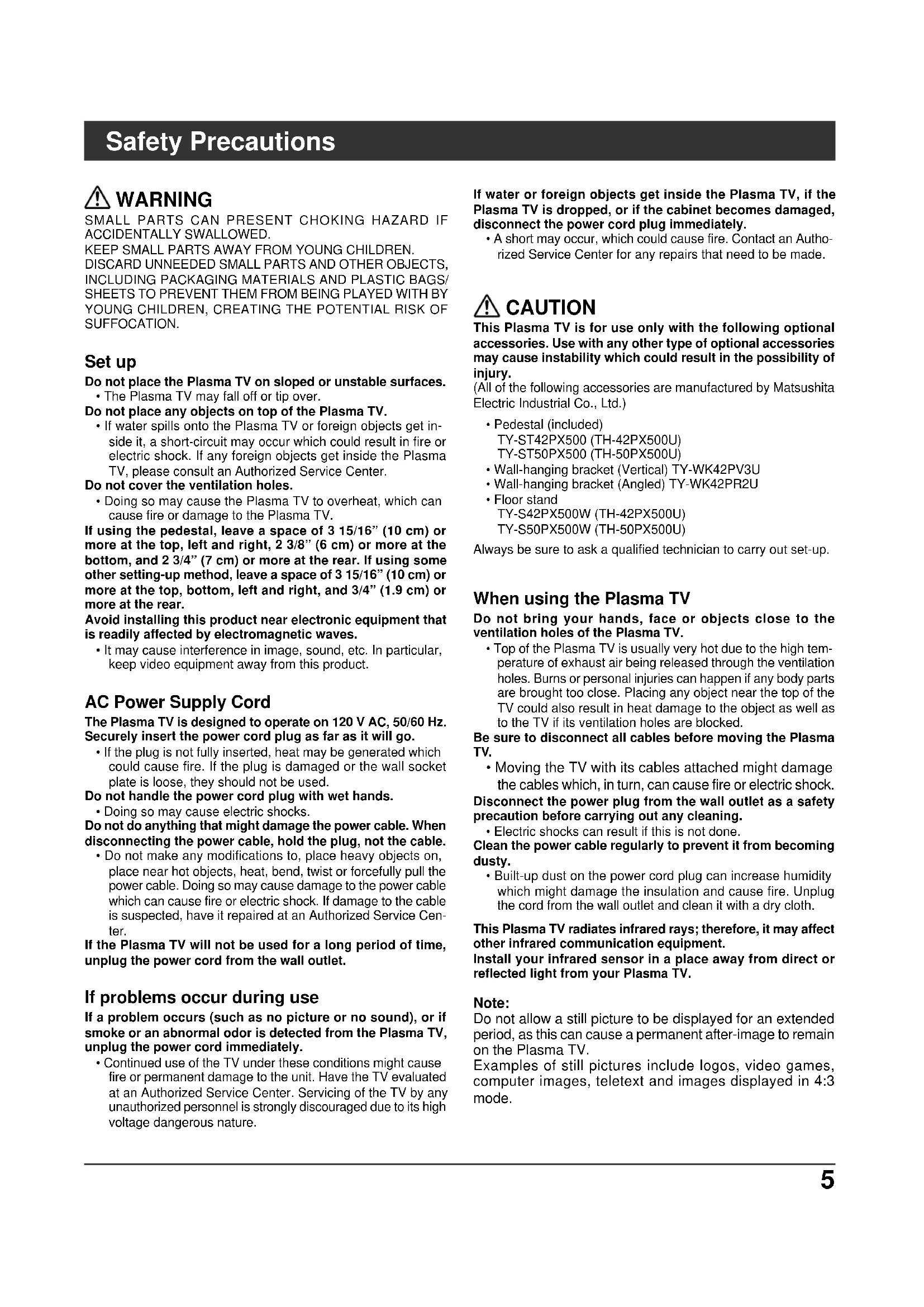
SHEETS TO PREVENT THEM FROM BEING PLAYED WITH BY YOUNG CHILDREN, CREATING THE POTENTIAL RISK OF SUFFOCATION. Set up Do not place the Plasma TV on sloped or unstable surfaces.
- The Plasma TV may fall off or tip over. Do not place any objects on top of the Plasma TV.
- If water spills onto the Plasma TV or foreign objects get in- side it, a short-circuit may occur which could result in fire or electric shock. If any foreign objects get inside the Plasma TV, please consult an Authorized Service Center. Do not cover the ventilation holes.
- Doing so may cause the Plasma TV to overheat, which can cause fire or damage to the Plasma TV. If using the pedestal, leave a space of 3 15/16” (10 cm) or more at the top, left and right, 2 3/8” (6 cm) or more at the bottom, and 2 3/4” (7 cm) or more at the rear. If using some other setting-up method, leave a space of 3 15/16” (10 cm) or more at the top, bottom, left and right, and 3/4” (1.9 cm) or more at the rear. Avoid installing this product near electronic equipment that is readily affected by electromagnetic waves.
- It may cause interference in image, sound, etc. In particular, keep video equipment away from this product. AC Power Supply Cord The Plasma TV is designed to operate on 120 V AC, 50/60 Hz. Securely insert the power cord plug as far as it will go.
- If the plug is not fully inserted, heat may be generated which could cause fire. If the plug is damaged or the wall socket plate is loose, they should not be used. Do not handle the power cord plug with wet hands.
- Doing so may cause electric shocks. Do not do anything that might damage the power cable. When disconnecting the power cable, hold the plug, not the cable.
- Do not make any modifications to, place heavy objects on, place near hot objects, heat, bend, twist or forcefully pull the power cable. Doing so may cause damage to the power cable which can cause fire or electric shock. If damage to the cable is suspected, have it repaired at an Authorized Service Cen- ter. If the Plasma TV will not be used for a long period of time, unplug the power cord from the wall outlet. If problems occur during use If a problem occurs (such as no picture or no sound), or if smoke or an abnormal odor is detected from the Plasma TV, unplug the power cord immediately.
- Continued use of the TV under these conditions might cause fire or permanent damage to the unit. Have the TV evaluated at an Authorized Service Center. Servicing of the TV by any unauthorized personnel is strongly discouraged due to its high voltage dangerous nature. If water or foreign objects get inside the Plasma TV, if the Plasma TV is dropped, or if the cabinet becomes damaged, disconnect the power cord plug immediately.
- A short may occur, which could cause fire. Contact an Autho- rized Service Center for any repairs that need to be made. CAUTION This Plasma TV is for use only with the following optional accessories. Use with any other type of optional accessories may cause instability which could result in the possibility of injury. (All of the following accessories are manufactured by Matsushita Electric Industrial Co., Ltd.)
- Pedestal (included) TY-ST42PX500 (TH-42PX500U) TY-ST50PX500 (TH-50PX500U)
- Floor stand TY-S42PX500W (TH-42PX500U) TY-S50PX500W (TH-50PX500U) Always be sure to ask a qualified technician to carry out set-up. When using the Plasma TV Do not bring your hands, face or objects close to the ventilation holes of the Plasma TV.
- Top of the Plasma TV is usually very hot due to the high tem- perature of exhaust air being released through the ventilation holes. Burns or personal injuries can happen if any body parts are brought too close. Placing any object near the top of the TV could also result in heat damage to the object as well as to the TV if its ventilation holes are blocked. Be sure to disconnect all cables before moving the Plasma TV.
- Moving the TV with its cables attached might damage the cables which, in turn, can cause fire or electric shock. Disconnect the power plug from the wall outlet as a safety precaution before carrying out any cleaning.
- Electric shocks can result if this is not done. Clean the power cable regularly to prevent it from becoming dusty.
- Built-up dust on the power cord plug can increase humidity which might damage the insulation and cause fire. Unplug the cord from the wall outlet and clean it with a dry cloth. This Plasma TV radiates infrared rays; therefore, it may affect other infrared communication equipment. Install your infrared sensor in a place away from direct or reflected light from your Plasma TV. Note: Do not allow a still picture to be displayed for an extended period, as this can cause a permanent after-image to remain on the Plasma TV. Examples of still pictures include logos, video games, computer images, teletext and images displayed in 4:3 mode.6 The front of the display panel has been specially treated. Wipe the panel surface gently using only a cleaning cloth or a soft, lint-free cloth.
If the surface is particularly dirty, soak a soft, lint-free cloth in a weak detergent solution and then wring the cloth to remove excess liquid. Use this cloth to wipe the surface of the display panel, then wipe it evenly with a dry cloth, of the same type, until the surface is dry.
- Do not scratch or hit the surface of the panel with fingernails or other hard objects. Furthermore, avoid contact with volatile substances such as insect sprays, solvents and thinner; otherwise, the quality of the surface may be adversely affected. Check that you have the Accessories and items shown Operating Instruction Remote control EUR7627Z50 or EUR7627Z80 Batteries for the remote control (AA Battery × 2) Pedestal TY-ST42PX500 (TH-42PX500U) TY-ST50PX500 (TH-50PX500U) Product Registration Card (for U.S.A.) Customer Care Plan Card (for U.S.A.)
- Wall-hanging bracket (Angled) TY-WK42PR2U
- Wall-hanging bracket (vertical) TY-WK42PV3U Cable clamper × 2 F-Type antenna adapter (for 5C-2V) ( × 1) AC cord IR Blaster ( × 1) TNQX016 Accessories Optional Accessories Cleaning and maintenance If the cabinet becomes dirty, wipe it with a soft, dry cloth.
- If the cabinet is particularly dirty, soak the cloth in a weak detergent solution and then wring the cloth dry. Use this cloth to wipe the cabinet, and then wipe it dry with a dry cloth.
- Do not allow any detergent to come into direct contact with the surface of the Plasma TV. If water droplets get inside the unit, operating problems may result.
- Avoid contact with volatile substances such as insect sprays, solvents and thinner; otherwise, the quality of the cabinet surface may be adversely affected or the coating may peel off. Furthermore, do not leave it for long periods in contact with articles made from rubber or PVC. Ferrite core Large size × 1 ZCAT3035-1330 Small size Gray color × 1 ZCAT2235-1030 White color × 4 RFC-8 Pull back the tabs (in two places) to open. Put the cable and close. Attaching the ferrite core Be sure to choose the appropriate size of ferrite core (large or small) and the correct setting of the cable (winding), as indicated by each connection diagram on the following pages (12, 14).
- Floor stand TY-S42PX500W (TH-42PX500U) TY-S50PX500W (TH-50PX500U)77 Installation The Video/Audio connection between components can be made with shielded video and audio cables. For best performance, video cables should utilize 75 ohm coaxial shielded wire. Cables are available from your dealer or electronic supply store. Before you purchase any cables, be sure you know what type of output and input connectors your various components require. Also determine the length of cable you will need. Receiver Location This unit is intended to be used with the stand or bracket. Consult your dealer for available options. Position for comfortable viewing. Avoid placing where sunlight or other bright light (including reflections) will fall on the screen. Use of some types of fluorescent lighting can reduce remote control transmitter range. Adequate ventilation is essential to prevent internal component failure. Keep away from areas of excessive heat or moisture. Optional External Equipment Remote Control Battery Installation For frequent remote control users, replace old batteries with alkaline batteries for longer life. Helpful Hints: Whenever you remove the batteries, you may need to reset the remote control infrared codes. We recommend that you record the code on page 54, prior to setting up the remote control. Helpful Hints:
1. Open the cover. 2. Install the batteries and replace the cover.
Note the correct polarity (+ and
Precaution on battery use Incorrect installation can cause battery leakage and corrosion that will damage the remote control transmitter. Observe the following precautions:
1. Batteries should always be replaced as a pair. Always use new
batteries when replacing the old set.
2. Do not combine a used battery with a new one.
3. Do not mix battery types (example: “Zinc Carbon” with “Alkaline”).
4. Do not attempt to charge, short-circuit, disassemble, heat or burn
5. Battery replacement is necessary when remote control acts
sporadically or stops operating the TV set. Two AA size8
VIDEO AUDIO IN AV IN R L AUDIO IN Cable binding instructions Cable cover 1 Push down hooks and pull the cover slightly towards yourself to disengage the claws (at 2 points). 2 Slowly pull out in the upward direction. Removal Fitting 1 Insert the claws (at 2 points) at the bottom end. 2 Push until it clicks. Clamper Open How to fix: AC cord Clamp Close Fix by pushing in until a clicking sound is heard. Pull down while drawing the knob. How to release: Note: To avoid interference appearing on the screen, do not bundle the RF cable and mains lead together. Attach the bands. Insert the spigot on the two bands into the pedestal. Connect cables. Example of “connection cable routing” Fastening band Fastening To tighten. Loosening Pull off. Keep the knob pressed. Band AC cord Clamp Binding strap Band Cable binding condition99 ANTENNA Cable In DIGITALAUDIO OUTG-LINKCableCARD
The RF input mode must be set to Antenna (see pages 19, 30). Note: Cables and connectors are not supplied with this set. Mixer UHFVHF Back of the TV 75 Ohm Coaxial Cable (5C-2V or higher specification) Antenna Terminal F-Type Antenna Connector
Incoming Cable signal Home antenna CableCARD
allows you to tune digital and high definition cable channels through the cable antenna. Consult your cable company on the availability of CableCARD
, unplug the TV and plug it back on and try the controls again. If this condition persists, please call Panasonic Customer Call Center for further instructions.
- Do not insert a PCMCIA card into CableCARD
(with upper side facing you) into CableCARD
slot on the back of the TV. Follow the messages displayed on the screen. Connection Procedure Antenna Connection CableCARD
Connection10 Connection Connect the IR Blaster if you wish to send remote control signals from the plasma TV to control the recording of a connected video recorder. Position the IR Blaster remote control emitter facing the signal sensor of the video recorder and you will be able to easily record programs from digital broadcasts using a video recorder connected to the plasma TV. Setting the IR Blaster IR Blaster Connection Place the IR Blaster in front of the signal sensor of the video recorder. (VCR) Read the video recorder operating instructions regarding positioning of the signal sensor. If necessary, use the double sided adhesive tape (included) to secure the IR Blaster to a flat surface. e.g. Television stand surface If you peel off the adhesive tape, the surface may become damaged. Once you have confirmed the video recorder is operating correctly, secure it by attaching the adhesive tape. DIGITALAUDIO OUTG-LINK IR Blaster (Supplied) Infrared emitter Video recorder (VCR) Video recorder G-LINK jack
Introduction to recording scheduling using the IR Blaster You may do recording scheduling from the TV Guide of this TV after installing the IR Blaster. (See page 43) The TV acts as a proxy for some remote control operations of the VCR. Setting the recording time, channel and recording mode, etc. Converts scheduling data displayed on the TV to a remote control signal and sends it Settings other than basic ones (such as recording time and channel) must be set on the VCR.
No need to set recording time or channel on the video recorder VCR INPUT / OUTPUT Connection With the IR Blaster connection setting timer recording can be done easily by using the TV GUIDE function in this set. AV IN R L AUDIO IN S VIDEO VIDEO
ANTENNA Cable In DIGITAL AUDIO OUT G-LINK Connection for recording to a VCR by using TV GUIDE Back of the TVG-LINK from PROG.OUT To INPUT 1 IR Blaster VCR Notes:
- The input signals connected to INPUT 1 cannot be output from PROG. OUT terminals. (both Video and audio) However, output can be obtained from optical Digital Audio terminals. (Input signals other than from INPUT 1 can be output from PROG. OUT.)
- When you make schedule recording using TV Guide with IR blaster, you have to select in your VCR Line-1 (L-1) and set your VCR in OFF condition. (Refer to the Operating Instruction manual of VCR)11
DIGIT AUDIO O G-LINK See optional equipment manual for further instructions for recording and monitoring. Notes:
- Depending on your DVD player and DVD-Audio software the copyright protection function may operate and disable optical output.
- External speakers cannot be connected directly to OUTPUT terminals.
- When ATSC channel is selected, the output from the DIGITAL AUDIO OUT jack will be Dolby Digital. When NTSC channel is selected, the output will be PCM. Optical digital audio cable Audio cable For a full Home Theater sound experience, an external Dolby Digital
decoder and a multichannel amplifier must be connected to the DIGITAL AUDIO OUT terminal on the TV.
Dolby Digital 5.1 channel surround sound delivers digital-quality sound. Dolby Digital provides five discrete full- bandwidth channels for front left, front right, center, surround left and surround right, plus a LFE (Low Frequency Effect) subwoofer channel. Back of the TV Notes:
- The input signals connected to INPUT1 cannot be output from PROG. OUT terminals. (both picture and audio) However, output can be obtained from optical Digital Audio terminals. (Input signals other than from INPUT1 can be output from PROG. OUT.)
- Connect the output of the Video recorder to INPUT1, when recording by using TV GUIDE.
- When a device (STB, DVD, etc.) is connected to the HDMI or COMPONENT terminals (see pages 12, 13), only audio signals will be output. No video signals will be output.
- When a schedule recording is activated on the TV Guide, the show will be recorded on a connected VCR. Please note that the screen will automatically be switched to the channel of the recorded show.
- When receiving digital channel signals, all digital formats are down-converted to composite NTSC video to be output through Program Out terminals.
- Some programs contain a Macrovision signal to prevent VCR recording.
1. Select Speakers “Off” in Audio menu (see page 27).
2. Adjust the amplifier volume to the desired level.
VCR AV cable Back of the TV DVD recorder Connection Program Out Connection (PROG OUT) Amplifier Connection (TO AUDIO AMP) Procedure12
INPUT 2 INPUT 1 This TV is capable of displaying 1080i, 720p, 480p and 480i DTV signals when connected to a DTV Tuner Set-Top Box (STB). This TV also utilizes a progressive scan doubler, which de-interlaces the NTSC signal and progressively scans the image.
- To view DTV programs, connect the STB to the component video input terminals (Y, P
- A DTV signal must be available in your area.
- Use a Panasonic DTV-STB (Digital TV-Set-Top Box) or DVD Player. Back of the TV Component Video cable Audio cable Note: All signals will be re-formatted for viewing on your plasma display. Note: The S Video input will override the composite video signal when S Video cable is connected. Connect either S Video cable or Video cable. S-Video cable Video cable Audio cable VCR Set Top Box DVD player Back of the TV CAMCORDER VIDEO GAME CONSOLE Connection Digital TV - Set-Top Box (DTV-STB) or DVD Connection Video Input Connection Connecting to the front AV terminals Push to open the front panel and connect equipment to front Audio/Video input terminals. Ferrite core (Large size) (supplied) A second VCR, video disc player, video game equipment and DSS equipment can also be connected to the video input terminals. See the optional equipment manual for details. Note: The S-VIDEO connection provides higher quality picture. It overrides other VIDEO connections. Use INPUT 3, AUDIO L and R with S-VIDEO connection. Audio cable Video cable S-Video cable CAMCORDER Ferrite core (Small size white color) (supplied)13
(High Definition Multi media Interface) is the first all digital consumer electronics A/V interface that supports uncompressed standard. The HDMI terminal supports both video and audio information. To the HDMI
input terminal, you can connect an EIA/CEA-861/861B
compliant consumer electronic device, such as a Set-Top Box or DVD player with HDMI or DVI output terminal. Input a High-bandwidth Digital Content Protection (HDCP) high-definition picture source to this HDMI terminal, so you can display high-definition pictures on this TV in digital form.
HDMI, the HDMI logo and High-Definition Multimedia Interface are trademarks or registered trademarks of HDMI Licensing LLC. 2.EIA/CEA-861/861B profiles compliance covers profiles for transmission of uncompressed digital video including high bandwidth digital content protection. 3.HDMI-DVI conversion cable (TY-SCH03DH): available from Panasonic Website. Consult your consumer electronics dealer for availability details. Notes:
- This input terminal is not intended for use with computers.
- All signals will be re-formatted for viewing on your plasma display. HDMI cable 1080i 720p 480p 480i No. of dots (H
480i Vertical scanning frequency (Hz) 59.94/60 59.94/60 59.94/60, 59.94/60 59.94/60 HDMI cable HDMI signal out Set Top Box DVD player Audio cable
- If connecting with an HDMI cable, it is not necessary to connect an audio cable.
- If connecting to equipment that has only a DVI output terminal, HDMI-DVI conversion cable and an audio cable are necessary.
- This HDMI connector is Type A.
- If you connect equipment without a digital output terminal, connect to the COMPONENT VIDEO, S VIDEO or VIDEO input terminal on the TV so you can enjoy an analog signal.
- If you cannot display the picture because your Digital Set-Top Box does not have a DIGITAL OUT terminal Output setting, use the component Video Input (or the S Video Input or Video Input). In this case the picture will be displayed as an analog signal.14
Notes: (1) Computer signals which can be input are those with a horizontal scanning frequency of 15 to 110 kHz and vertical scanning frequency of 48 to 120 Hz. (However, the image will not be displayed properly if the signals exceed 1,200 lines.) (2) The maximum resolution: If the display resolution exceeds these maximums, it may not be possible to show fine detail with sufficient clarity. (3) Some PC models cannot be connected to the set. (4) There is no need to use an adapter for computers with IBM PC/AT compatible D-sub 15P terminal. (5) The computer shown in the illustration is for example purposes only. (6) Additional equipment and cables shown are not supplied with this set. Signal Names for D-sub 15P Connector Pin Layout for PC Input Terminal COMPUTER Audio Connect a cable which matches the audio output terminal on the computer. Conversion adapter (if necessary) RGB PC cable Connection D-sub 15p Stereo plug Pin No.
NC (not connected) GND (Ground) Pin No.
Signal Name GND (Ground) GND (Ground) GND (Ground) NC (not connected) GND (Ground) Signal Name NC (not connected)
Aspect PC Input Terminals Connection Less than 10cm (4”) Ferrite core (Small size gray color) Ferrite core (Small size white color) Less than 10cm (4”)1515
- Fix the power cord plug securely with the clamper (see page 8). Remote control sensor Within about 23 feet (7 meters) in front of the TV set. Notes:
- The TV will still consume some power as long as the power cord is inserted into the wall outlet.
- The First time setup screen is displayed only the first time you turn the power on after purchase. If you wish to change the settings of these items later, select them via the Setup menu.
Adjust the volume level. (Move cursor to right or left during menu mode.) Change the TV Channel. (Move cursor to up or down during menu mode.) Change the input mode. Press POWER button on front of this unit. First time setup is displayed on screen. (Refer to page 18-20 for operation)
Press to turn the TV on or off.
Connect the plug to the wall outlet.
FFREW PROG RETURN VCR DVD DTV RCVR DBS/CBL
SPLIT SWAP PLAY FFREW STOP
Access SD Memory Card.(see page 39). Operation of other Device (see page 56) SWAP Swap pictures in SPLIT operation (see page 52). SPLIT Split Screen (see page 52) Location of Controls
- Press corresponding number key on the remote control to select the input of your choice. Note: Video input can also be selected by pressing TV/VIDEO
then the CH buttons, then pressing “OK” key. R-TUNE Switch to previously viewed channel and input modes. TVGUIDE PAGE INFO Page scroll on TV Guide Press to display a help screen on TV Guide Press to enter the TV Guide (see page 43)17 SAP
- Digital channel Select the audio track (if available).
- Analog channel Cycle through different audio modes. LIGHT Illuminate the remote control buttons. The selected button blinks when lit. RECALL Display or remove the channel banner. ASPECT Change the screen aspect (see page 51). MUTE Mute the sound. Press again to cancel mute. FAVORITE Channel numbers registered in Favorite are displayed on the favorite tune screen. Select the desired broadcast station with the cursor, or using number keys. SLEEP timer (minutes) EXIT menus Normal viewing, from each menu.
: When tuning digital channel, press the button to enter the minor number in a compound channel number.
- To enter the channel number e.g. CH 15-1: [1] [5] [-] [1] [OK] Location of Controls CH: Change to the next channel up. : Move cursor upward during menu mode.
: Move cursor to the left during menu mode. VOL
: Move cursor to the right during menu mode. CH: Change to the next channel down. : Move cursor downward during menu mode. Direct program number selection buttons Audio Track 1 of 1 (English)18
First time setup For your convenience, First time setup menu will be displayed on screen when the set is turned on for the first time. If needed, follow the menus and procedures displayed on-screen for setting up the features. You can also adjust the settings in Setup menu (see pages 29-31). Allows you to select the language used for On Screen Displays. Press to select “Language”. Press to display “Language” screen. Language Press to select “Date”. Press and release immediately to change the day; press and hold to change the month. Press to select “Clock”. Press to display the clock adjust screen. Press to select “English”, “Español” or “Français”. Press to select “Mode”. Press to select “Manual” or “Auto”. Manual : Registers the time set by user. Auto : Updates the clock time by extracting time information from the digital broadcast. Date Valid when Mode is set to manual. Press to move the cursor to
Press to go to previous screen. Mode
inserted. You can scan All (Analog and Digital) channels. If needed, follow the menus and procedures displayed on-screen for setting up the features. You can also adjust the settings in Setup menu. Press to select “Time”. Press to adjust “Time”. If the button is held, the speed of change increases. Press to select “Time zone”. Press to select your zone. Press to select “DST” (Daylight saving). Press to select “On” or “Off”. Time Valid when Mode is set to manual. Time zone Valid when Mode is set to “Auto”. Daylight saving Valid when Mode is set to “Auto”.
Auto program ANT In Mode Start scan Cable All Auto program ANT In Mode Start scan Cable All
First time setup Press to select “Auto program”. Press to display “Auto program” adjust screen.
Press to select “Mode”. Press to select “All” or “Analog ”. Press to select “ANT In”. Press to select “Cable” or “Antenna”.
Press to select “Start scan”. Press to start. Channels available for reception will be set automatically.
- After Auto program is complete, the unit will return to Manual Program mode.
Press EXIT : To exit the menu screen Now scanning analog channel ... Progress Auto program ANT In Mode Start scan Cable All Auto program
First time setup Language Clock Auto program To make available a channel that has been located by auto scan, in the Manual program mode, move the cursor to “Apply” and press
key.20 INITIAL GUIDE SETUP for TV Guide First time setup Reminder Screen If you previously skipped TV Guide setup, you see the Reminder Screen when you power On your TV.
Press OK to begin TV Guide setup. Follow the instructions on the screen to perform setup. (See pages 49-51) Move the highlighting to select an option. Press OK to choose the option.
Welcome Screen The Welcome Screen is displayed at first time setup.
- Set up TV Guide On Screennow : TV Guide setup begins. Follow the instructions on the screen to perform setup. (See page 49, INITIAL GUIDE SETUP for TV Guide)
- Remind me to set it up later : The system returns to the normal TV screen.
- Don’t remind me again : The system returns to the normal TV screen. The Reminder Screen will no longer be displayed when power is turned On. Note: If you decide not to setup the TV Guide now, this reminder screen will appear each time you power On the TV (except if you selected “Don’t remind me again”). The TV Guide Welcome Screen is displayed at first time setup. Follow the guidance shown on the screen.2121
Watching TV programs NOTE: The factory default setting is to display the TV Guide channel list whenever the TV is initially powered On. To disable this default mode and view a TV channel on every power on, perform the following operations.
Press to operate the TV set with the remote control. 2 Press to turn the TV on. TV Guide is displayed. Please refer to page 43 for the TV Guide description and operating instruction. 3 Press to exit from the TV Guide on screen display. 4 Press channel up/down buttons to tune to the desired channel.
- You can also use the direct program number selection buttons and PROG–button (see page 17). Select the desired volume level. EXIT
Press ‘TV Guide’ remote button & select “SETUP” in the Service Bar of the TV Guide. 2 Press to select “Change default options”. Press to display “Change default options”. 3 Press to select “General defaults”. Press to display “General defaults” in Panel Menu. 4 Press to select “auto guide”. Press to select “off”. 5 Press to select “done”. Press to store the “setup”. TV Guide channel listing will no longer appear.
All Auto programANT In Mode Start scanProgram lock MPAA U.S.TVC.E.L.R.C.F.L.R.Monitor out Enter password.
Lock Mode Channel Program Change password Off
Press to move the highlighting.Press to choose the option andcontinue to the next mode. Input labels
Press to select the sub-menu. Press to adjust the sub-menu. Choose the pre-set picture mode that best suits the program you are viewing. This feature also affects Color Temp setting. Note: Each mode has its own picture settings (Picture, Brightness, Color, Tint and Sharpness). Press to select “Pic. mode”. Press to select the picture mode.
- Vivid (default): Provides enhanced picture contrast and sharpness for viewing in a well-lit room.
- Standard : Recommended for normal viewing conditions with subdued room lighting.
- Cinema : For watching movies in a darkened room. It provides a soft, film-like picture. Pic. mode Normal / Picture / Brightness / Color / Tint / Sharpness / Color Temp / Color Mng. / C.A.T.S Menu Navigation Press to select “Picture”. Press to enter sub-menu. Press the MENU button to display the Main menu. Picture Item Explanations Normal Picture Brightness Color Tint Sharpness Color Temp (Temperature) Color Mng. (Color Management) C.A.T.S. Resets all picture adjustments to factory default settings. Adjusts white areas of picture. Adjusts dark areas of picture. Adjusts desired color intensity. Adjusts natural fresh tones. Adjusts clarity of outline detail. To increase or decrease Warm (red) and Cool (blue) colors to suit personal preferences. Color Mng. On enhances green and blue color reproduction, especially outdoor scenes. Plasma C.A.T.S. (Contrast Automatic Tracking System) automatically senses the ambient light conditions and adjusts the brightness and gradation accordingly, to optimize contrast.25
Menu Navigation Adjust the Zoom position. It works when Aspect mode is Zoom. Press to select Zoom Adjust menu. Press to display the Zoom Adjust screen. Other Adjust Press to select the sub-menu. Press to select or adjust the sub- menu. Press to select “Other Adjust”. Press to display other Adjust menu. Item Explanations Video NR 3D Y/C Filter Color Matrix MPEG NR Black level Reduces noise, commonly called snow. Leave off when receiving a strong signal. Minimizes noise and cross-color in the picture. Select SD or HD.
- SD : When the input signal is a normal TV system (NTSC).
- HD : When the input signal is a High-Definition system (ATSC). Displays 480p input signals in natural color from digital equipment adapters connected to
) terminals. Select HD or SD to adjust color parameters automatically for HD (high definition) or SD (standard definition). Note: This feature is available only with 480p signal and not available with regular TV (NTSC) program. Digital noise unique to DVD, STB, etc. will be reduced. Select Dark or Light. Valid only for external input signals. Zoom Adjust Press to adjust V-Position. Press to adjust Size.
- V-Position: Adjust the vertical position.
Menu Navigation PC Adjust During “RGB / PC” input signal. Press to select “PC Adjust”. Press to display the PC Adjust screen. PC Adjust 1/2 Normal Sync Dot Clock H-Position V-Position
PC Adjust 2/2 Clock Phase Input Resolution
- H & V: The H and V sync signals are input from the HD/VD connector.
- On G : Uses a synchronized signal on the Video G signal, which is input from the G connector. Dot Clock Alleviates the problem if a picture appears to be vertically-striped, flickers partially or is blurred. H-Position V-Position Clock Phase Alleviates the problem if the whole picture appears to flicker or is blurred. First adjust the Dot Clock to get as good a picture as possible, then adjust the Clock Phase so that a clear picture appears. Note : It may not be possible to display a clear picture due to poor input signals. Input Resolution Switches to wide display. Input signal switched from VGA to WVGA Input signal switched from XGA to WXGA H-Frequency/V-Frequency (Displays the frequencies of the PC signal currently being adjusted.) Displays the H (Horizontal)/V (Vertical) frequencies. Display range: Horizontal 15 - 110 kHz Vertical 48 - 120 Hz H-Frequency V-Frequency
Adjust the horizontal position. Adjust the vertical position.
Audio Normal Bass Treble Balance Other Adjust
Other Adjust AI Sound
- Off : For monaural audio. Note: Fixed to “Off” when “Speakers” is set to “Off”. Speakers This feature is used to turn TV speakers “On” or “Off” (see page 11, Amplifier Connection).
- On : TV speakers operate normally.
- Off : TV speakers off. Note: “AI Sound”, “Surround” and “Audio Leveler” are not available when selecting “Off”. HDMI In When using HDMI (see page 13), this feature will let you switch between Analog or Digital Input.
- Analog : Analog Input only. Audio Leveler The audio leveler monitors the difference in audio levels between input signals from external equipment and minimizes the change in output volume that could occur when switching input signals. Note: “Audio Leveler” is not available when “Speakers” is set to “Off”. Press to select “Audio”. Press to enter sub-menu. Press the MENU button to display the Main menu. Reset Bass, Treble and Balance adjustments to factory default settings. Increase or decrease the bass response. Increase or decrease the treble response. Emphasize the left / right speaker volume. AI Sound Equalize overall volume levels across all channels and VIDEO inputs. Note: Fixed to “Off” when “Speakers” is set to “Off”.
BBE VIVA 3D provides a musically accurate natural 3D image with hi-fi sound. The clarity of the sound is improved by BBE while the width, depth and height of the sound image are expanded by BBE’s proprietary 3D sound processing. BBE VIVA 3D is compatible with all TV programs including news, music, dramas, movies and sports as well as electronic games. BBE VIVA 3D enhances the surround sound effect, while maintaining the clarity of dialogue. BBE Sound technology enhances speech intelligibility and restores the dynamic range of musical passages to provide outstanding natural sound. Press the “OK” key to display “Other Adjust” menu. (See below) Normal / Bass / Treble / Balance Other Adjust28
Day On time Off time Set Press to select “Timer 1” - “Timer 5”. Press to enter the timer adjust screen.
Press to select “On time” / “Off time”. Press to select hour (AM or PM) and the minutes of “On time” / “Off time”. Press to select “Set”. Press to select “On” or “Off”. Perform the following operations for both “On time” and “Off time”. Press to select “CH”. Press to set “CH”.
Select Timer to turn the TV on and off at selected times and on selected days. Press the MENU button to display the Main menu. Press to select “Timer”. Press to enter the sub-menu. Press to select “Sleep”. Press to enter the Sleep set screen.
Press to select “Day”. Press to select appropriate day setting. Press to select off time (minutes). Notes:
- The TV automatically turns Off after 90 minutes when turned On by the Timer. This operation will be cancelled if the Off time is selected or if a key is pressed.
- When the power to the TV set is disrupted due to a power outage or similar problem, the off-timer will be deactivated and the TV will be in standby mode even after power is restored. The Clock must be set before On time/Off time settings can be made. (See pages 18-19, 29) Menu Navigation Sleep timer Timer set Timer On time / Off time Set Channel Day To return to the previous screen RETURN Press to return. Selectable day items SUN, MON, TUE, WED, THU, FRI, SAT, MON-FRI, SAT-SUN, DAILY, EVR SUN, EVR MON, EVR TUE, EVR WED, EVR THU, EVR FRI, EVR SAT Before selecting Channel in Timer 1~Timer 5 make sure that the channel you’re selecting is programmed into memory. (Refer to Auto program in page 19)29
Menu Navigation Press to select “CH scan”. Press to select “Fav.” or “All”. Please read about Language in First time setup on page 18. Press to select “Setup”. Press to enter the sub-menu. Press to select “Language”. Press to display the Language screen. Press to select “Clock”. Press to display the Clock screen. Please read about Clock in First time setup on pages 18-19. Press the MENU button to display the Main menu. Set up CH scan Language Clock30
Press to select “Manual”. Press to enter the Manual Program screen. Press to select “Edit”. Press to enter the edit mode. Press to select the desired preset channel line. Press to select edit area. “Caption”, “Favorite”, “Add”. Press to enter the preset screen. Refer to next page for each adjustment. Press to move cursor to “Apply”. Press to enter your program.
Program edit Menu Navigation Program CH Press to select “Program channel”. Press to enter Program channel menu. Press to select “Mode”. Press to select “All” or “Analog”. All : Analog and Digital Analog : Analog only Press to select sub-menus. Press to enter sub-menu. Auto program Automatically scans all available channels. “Auto program” is not available while the CableCARD
is inserted. Press to select “ANT In”. Press to select “Cable” or “Antenna”. Press to select “Start scan”. Press to start.
- After Auto program is complete, the unit will return to Manual Program mode. Manual program To add or delete channels from channels list manually. To make available a channel that has been located by auto scan, in the Manual program mode, move the cursor to “Apply” and press
key. “Auto” and “Signal meter” cannot be selected while the CableCARD
is inserted. Program channel Auto Manual Signal meter Edit
Program channel Auto Manual Signal meter Now scanning analog channel ...Progress
Auto program ANT In Mode Start scan Cable All Auto program ANT In Mode Start scan Cable All Auto program ANT In Mode Start scan Cable All31
Press to select “Signal meter”. Press to display “Signal meter”. Press to select “Preset”. Press to select Broadcast station. Press to select “Caption detail”. Press to display the Caption detail screen. Press to move cursor to “Caption”. Press to enter input field. Press to select the character to input/ change. Press to move to next character. You may enter up to 7 characters. Press to enter your selection. Press to move cursor to “Apply”. Press to enter “Caption” and return to Edit screen. Edit (Caption)
Edit (Favorite) Press to select “Favorite”. Press to select Favorite number. Edit (Add) Setting to register/delete in Program channel. Press to select Yes or No. Press to select desired channel. Press to turn desired channel. Signal meter (For digital channels only) Displays the signal strength of the ATSC digital channel in Antenna. “Signal meter” is not available while the CableCARD
Press to move the cursor to “Apply”. Press to enter “Favorite” and return to Edit screen. Note: The signal meter works only for digital signals input via the antenna. Menu Navigation Apply Caption detail
The television includes a built-in decoder that is capable or providing a visual display of the audio portion. The program viewed must provide Closed Captioning (CC) for the television to display it. Notes:
- The closed caption is not displayed when you use HDMI connection and PC inputs.
- If analog connected equipment is used for displaying or recording, closed caption (CC) should be set On/Off on the connected equipment. The CC mode setting of the TV will not affect the analog input. If a digital program is being output in analog format, the CC data will also be output in analog format. If digital connected equipment is used for input, CC should be set On on either the connected equipment or the TV. If CC is set On on both the connected equipment and the TV, captions from each unit will overlap. Press to select “Mode”. Press to select the setting.
- Off : Recommended mode when Closed Caption is not being used.
- On : To display Closed Captions. CC Mode Press to select “Analog”. Press to select the setting.
- CC1 : For video related information that can be displayed (up to 4 lines of script on the screen, where it does not disturb the relevant parts of the picture). Script can be in any language.
- CC2/CC3/CC4 : Other modes used for video related information.
- T1 : Blanks out a large portion of the picture on the television screen, and displays program guide or any other information currently being transmitted.
- T2/T3/T4 : Other modes that display information and blank out a large portion of the picture of the TV screen. Analog Choose the closed caption service of Analog broadcasting. Input labels CC (Closed Caption) Selectable input labels : SKIP, VCR, DVD, CABLE, DBS, PVR, GAME, AUX SKIP Input labels PC33 Menu Navigation
Press to select “Digital”. Press to select the setting.
- “Primary”, “Second.”, “Service 3”, “Service 4”, “Service 5”, “Service 6”
- Size : “Automatic”, “Normal”, “Small”, “Large”
- Font : “Automatic”, “Default”, “Mono-serif”, “Prop-serif”, “Mono”, “Prop”, “Casual”, “Cursive”, “Small caps”
- Style : “Automatic”, “None”, “Raised”, “Depressed”, “Uniform”, “Drop shadow”
- Foreground : The color of the font (“Automatic”, “Black”, “White”, “Red”, “Green”, “Blue”, “Yellow”, “Magenta”, “Cyan”)
- Fore opacity : The opacity of the font (“Automatic”, “Transparent”, “Translucent”, “Solid”, “Flashing”)
- Background : The color of the text box (“Automatic”, “Black”, “White”, “Red”, “Green”, “Blue”, “Yellow”, “Magenta”, “Cyan”)
- Back opacity : The opacity of the text box (“Automatic”, “Transparent”, “Translucent”, “Solid”, “Flashing”)
- Outline : The outline of the text (if selected under style)(“Automatic”, “Black”, “White”, “Red”, “Green”, “Blue”, “Yellow”, “Magenta”, “Cyan”) Digital The Digital Closed Caption menu lets you configure the way you choose to view the digital captioning. Press to reset Closed Caption settings. Press to select “Digital setting”. Press to enter the Digital setting menu. Digital setting Selecting digital broadcast service and viewing formats. Press to select the sub-menu. Press to select the setting.
CC Reset Reset the CC settings. Press to select “CC reset”.
Auto Power On Press to select “Auto Power On”. Press to select “Set” or “Off”. Select “Set” to power the TV on at the same time as the cable box or other connected components are powered on. Side Bar Adjustment Do not display a picture in 4:3 mode for an extended period, as this can cause an after-image to remain on either or both sides of the display field. To reduce the risk of such an after-image, change the brightness of the side bars. Press to select “About”. Press to display the About screen. Display the TV set version, Software License and CableCARD
information. Press to select “Version”, “License” or “CableCARD”. Press to display “Version”, “License” or “CableCARD”. Press to select “Side bar”. Press to select “Off”, “Dark”, “Mid”, “Bright”. Notes:
- To reduce the occurrence of after-images, set the “Side Bar” to “Bright”.
- The side bar may flash (alternate black/white) depending on the picture. Using Cinema mode will reduce such flashing (see page 24). Press to select “Reset”. Press to display the password screen. Setup is reset. Note: The Sleep Timer and On / Off timer will not function if “Auto Power On” is set. Note: Performing Reset will clear all items set with Setup, such as channel settings. Use Reset with care. The confirmation screen is displayed. Select “Yes”, and press
key. CableCARD This menu is used to provide information when a CableCARD
is inserted into the CableCARD
slot on the back of the television. “CableCARD” is not accessible without inserting a CableCARD
slot. To receive the features offered by your cable company, you may have to subscribe to those services. Note: Please contact your cable company regarding availability of the CableCARD
is needed to receive premium digital services (where available) through the Cable input. You may also be able to order call- ahead pay per view events. About Reset after- images Enter your password by pressing
keys to reset the Setup settings. Other adjust (Setup) Side Bar Menu Navigation35 Lock Mode Channel Program Change password Off Picture Audio Timer Lock Memory card TV Guide Setup Lock Mode Channel Program Change password Off Lock Mode Channel Program Change password Off Channel lock CH 1 CH 2 CH 3 CH 4 CH 5 CH 6 CH 7
Press to select “Mode”. Press to select the setting.
- Off : Turns off Lock set functions.
- All : All channels and Video inputs are locked regardless of the rating level.
- Game : Locks out CH 3, 4 and Video inputs.
- CH : Locks out specific analog and digital channels. Password is required to view any of the locked channels. Press the MENU button to display the Main menu. Press to select “Channel”. Press to display the channel block screen. Press to select “CH 1” - “CH 7”. Press to select the desired Block channel. Select up to 7 (1-7) channels to be blocked out. These channels will be blocked out regardless of the program rating. Press to select “Lock”. Press to display the Input password screen. Create a 4-digit password to enter the Lock menu. Enter a 4-digit password. After entering your password for the first time, “Create password.” will change to “ Enter password.”. Notes:
- Use a code that is easy to remember and record it in a safe place.
- If you forget your secret code, the TV must be serviced by a qualified technician to clear the Lock setup. Select Lock mode to prevent viewing of video games, VCR tapes, channels and Video modes. Enter your password by pressing
keys. Menu Navigation Lock Lock mode Channel (Block channel selection)36 Menu Navigation This television incorporates V-Chip technology to block the viewing of movies and television programs according to the rating category. There are four (4) Content Advisory Categories: MPAA (Motion Picture Association of America), U.S.TV Program, Canadian English ratings and Canadian French ratings. These categories are used as guidelines for blocking programs.
- The default mode for the Lock category is the Unlocked state. Press to select “MPAA”, “U.S.TV”, “C.E.L.R.” or “C.F.L.R.”. Press to enter Block program adjust screen. MPAA : for U.S movie ratings U.S.TV : for U.S TV program ratings C.E.L.R. : for Canadian English ratings C.F.L.R. : for Canadian French ratings Press to select “Monitor out”. Press to select “On” or “Off”. Monitor out : On Turns on the monitor terminal output for programs that have been set to “Blocked.” Off Turns off the monitor terminal output for programs that have been set to “Blocked.” Press to highlight the desired rating level. Press to select “Program”. Press to enter Program menu. Block program Notes:
- The Off rating is independent of other ratings.
- When placing a block on a specific age based rating level, the Off rating and any other more restrictive ratings will also be blocked. Lock Mode Channel Program Change password
Program lock MPAA U.S.TV C.E.L.R. C.F.L.R. Monitor out
U.S. TV PROGRAMS RATINGS CHART
CANADIAN ENGLISH RATINGS CHART
Description Not Rated. See CUSTOMER CAUTION on page 38. All children. The themes and elements in this program are specifically designed for a very young audience, including children from ages 2-6. Directed to older children. Themes and elements in this program may include mild physical or comedic violence, or may frighten children under the age of 7. General audience. It contains little or no violence, no strong language, and little or no sexual dialogue or situations. Parental guidance suggested. The program may contain infrequent coarse language, limited violence, some suggestive sexual dialogue and situations. Parents strongly cautioned. This program may contain sophisticated themes, sexual content, strong language and more intense violence. Mature audiences only. This program may contain mature themes, profane language, graphic violence, and explicit sexual content. NO RATING (NOT RATED) AND NA (NOT APPLICABLE) PROGRAMS. Movie has not been rated or rating does not apply. GENERAL AUDIENCES. All ages admitted. PARENTAL GUIDANCE SUGGESTED. Some material may not be suitable for children. PARENTS STRONGLY CAUTIONED. Some material may be inappropriate for children under 13. RESTRICTED. Under 17 requires accompanying parent or adult guardian. NO ONE 17 AND UNDER ADMITTED. ADULTS ONLY.
Exempt - Exempt programming includes: news, sports, documentaries and other information programming, talk shows, music videos, and variety programming. Programming intended for children under age 8. No offensive language, nudity or sexual content. Programming generally considered acceptable for children 8 years and over. No profanity, nudity or sexual content. General programming, suitable for all audiences. Parental Guidance suggested. Some material may not be suitable for children. Programming contains themes or content which may not be suitable for viewers under the age of 14. Parents are strongly cautioned to exercise discretion in permitting viewing by pre-teens and early teens. 18+ years old. Programming restricted to adults. Contains constant violence or scenes of extreme violence.
14+ 18+ The TV Parental Guidelines has 7 levels of age-based ratings that can be selected. These 7 levels are split into 2 age- based groups: Youth Age-based Ratings and Guidance Age-based Ratings. Some of these age-based ratings can also have content- based ratings, denoted as D (Dialog), L (Language), S (Sex) and V (Violence).The table below shows the age-based ratings selection. Age-based Ratings TV-NR TV-Y TV-Y7 TV-G TV-PG TV-14 TV-MA Age-based Group
(Not Rated) Youth Guidance Possible Content Selections
- D,L,S,V (all selected)
- Any combination of D, L, S, V
- D,L,S,V (all selected)
- Any combination of D, L, S, V
- L,S,V (all selected)
- Any combination of L, S, V FV : Fantasy/Cartoon Violence. V : Violence S:Sex L : Offensive Language D : Dialogue with sexual content.38 Menu Navigation Various Blocking messages are displayed on-screen depending upon the type of blocking you have selected in the Lock menu. Note: Entering the password will override the block condition. However, the ratings selection will be retained. Message Game locked. Channel locked. All locked. Program locked.
CANADIAN FRENCH RATINGS CHART
Exempt - Exempt programming.General - Programming intended for audience of all ages. Contains no violence, or the violence content is minimalor is depicted appropriately.8+ General - Not recommended for young children. Programming intended for a broad audience but contains lightor occasional violence. Adult supervision recommended.Programming may not be suitable for children under the age of 13 - Contains either a few violent scenes or one ormore sufficiently violent scenes to affect them. Adult supervision strongly suggested.Programming may not be suitable for children under the age of 16 - Contains frequent scenes of violence or intenseviolence.Programming restricted to adults. Contains constant violence or scenes of extreme violence.
8 ans+13 ans+16 ans+18 ans+ The V-Chip system that is used in this set is capable of blocking “NR” programs (non rated, not applicable and none) as per FCC Rules Section15.120(e)(2). If the option of blocking “NR” programs is chosen “unexpected and possibly confusing results may occur, and you may not receive emergency bulletins or any of the following types of programming:” Customer Caution
- Emergency Bulletins (Such as EAS messages, weather warnings and others)
- Locally originated programming • News • Political • Public Service Announcements • Religious • Sports
- Weather Possible cause The [TV/VIDEO] button was pressed when the Game lock had been selected. Tuned to CH 3 or CH 4 when the Game lock had been selected. Tuned to the designated channel when the Channel lock had been selected. Lock all is selected. Received program that exceeds the Block Program rating level. Press to select “Change password”. Press to enter the Input Password screen. Blocking Messages Change password Lock Mode ChannelProgramChange password Enter new password. Enter new password, again.
SD cardPC card Photo Viewer Still image data (JPEG) made with a digital camera or digital video camera can be played back using an SD Card/ PC Card.Displayable Image Formats: Baseline JPEG 160 120 – 2,560 1,920 pixels (sub-sampling 4:4:4, 4:2:2 or 4:2:0) SD card slotInsert the card.Remove the card. PC card slotTurn the TV off before inserting or removing a PC card.Insert the card.Remove the card.Label-sideupwardInsert it to beclicked in.Push the center ofthe card.1. Push the EJECT button pops out.2. Push it again.If the eject button does not pop outPush in PC card again, and then push the eject buttonagain.Note:If PC card adapter is used, remove it together with theadapter.Press to select “Memory Card”.Press to display the CARD selection menu.Press MENU to display the Main Menu screen.The SD button may also bepressed for Photo Viewermode.As with any small object, SD cards can be swallowedby young children. Do not allow children to handle theSD card.1. Always insert card in the correct direction. Failure to doso may result in damage to the card and this unit.2. The SD Card is precision devices. Do not subject themto excessive pressure or strong impacts.Note:Suitable SD Memory Cards. Please confirm the latest information on the following website.http://panasonic.co.jp/pavc/global/cs (This site is in English only)Inserting and removing a cardPress to select “SD card” or “PC card”.Press to enterthe Photo Viewer.Holdingboth edges,securely insert it tothe depth.Terminal face tothe depth.Label-side upwardAlign thedirection mark. WARNING CAUTION40 Photo Viewer miniSD Card requires miniSD adapter.
- This function is not compatible with card type hard disk (Micro Drive, Mobile type hard disk, etc).
- Memory cards are not supplied with this television. Card Data Protection
- Do not remove the card while the unit is accessing the information. Such action may damage the memory card or the unit itself.
- Before inserting or removing the PC card, make sure that the TV is turned Off. Otherwise, it may damage the unit.
- Do not touch the terminals on the back of the SD card/PC card.
- Always insert a card in the correct direction. Failure to do so may result in damage to the card and this unit.
- Do not subject the card to excessive pressure or strong impacts.
- Electrical interference, electrostatic discharges and malfunctions of the unit or card may all result in data loss or damage to the card.
- Stored data should be periodically backed up as a protection against data corruption, data loss or device malfunction. Please note that our company shall not accept any liability for damage or loss of stored data. Compatible card type and card size PC card slot
Memory Stick Pro (1GB) The cards require standard PC card adapter. (Some PC card adapter will not be compatible.) SD card slot
(128MB) JPEG thumbnail If “Is memory card in?” appears, check if a card is inserted. If not, turn the unit power off, correctly insert a card, then turn the unit back on. Now, place unit into JPEG Viewer mode. Card Warning Messages If there is a problem with the card or card data, the following messages will appear. Is memory card in? No file. A card may not be inserted, or the card format may not be supported. (Use SD cards formatted in a digital camera.) The card may not contain image data, or all images on the card may be incompatible. Message description Total number of JPEG images on the inserted card is displayed. Selected picture information is displayed. No. : Image number or file name is displayed. Date : Date of recording is displayed. Pixel : Display resolution is displayed. Note: Depending on the JPEG type, Info contents may not be displayed correctly. Notes:
- Only JPEG files can be displayed.
- Up to 9,999 JPEG files can be displayed.
- If images have duplicate numbers, none of the images will be displayed.
- Depending on the JPEG type, it may not be displayed normally. Navigation Area Operational buttons are displayed as “GUI” (Graphical User Interface). “Accessing” is displayed while data is read. Index Area JPEG images contained on the inserted card are displayed for viewing. JPEG thumbnailAccessing Info Total 8No. 102-0001Date 01/01/2000Pixel 2048x1536102-0001 102-0002 102-0003102-0004 102-0005 102-0006102-0007 102-0008SelectSelect
MENU RETURN Afterimage prevention function If still image data is displayed for more than a few minutes, the afterimage prevention function will activate and the image disappears.41 Press to move cursor to desired file in INDEX AREA. Press to display file in full screen size.
MENU RETURN VOL VOL VOL VOL VOL VOL Photo Viewer Index Area Operation Rotate image Press to select icon. Press to display full size file preview. Notes: File names will not be displayed correctly if...
- More than 8 characters are used.
- Spaces and special symbols are used. Use care when changing file names. Picture Adjustment Navigation Display Pressing RECALL while in Single Play Mode displays or removes the Navigation Area screen. Change image Note: Rotation settings are not written to the file and are cancelled when Photo Viewer is exited. When MENU is pressed, the Picture Adjust menu (see page
Pressing RETURN to exit Picture menu. Exit Single Play mode Pressing RETURN during Single Play mode allows you to exit the mode. Press RETURN with Single Play mode displayed to return to the JPEG thumbnail mode. Single Play Mode Navigation Area Picture Adjustment Press to changes the displayed image. Press :The previous image is displayed. Press : The next image is displayed. Press to rotates the image 90° at a time. Press [VOL
during a slide show to stop it. The Submenu is displayed.
Exit Slide Show mode Pressing RETURN during Slide Show mode allows you to exit the mode. Navigation Display Pressing RECALL during Slide Show mode allows you to display or remove the Navigation Area. Navigation Area Press to start slide show. Press RETURN with Slide Show mode displayed to return to the JPEG thumbnail mode. Digital cameras that are compliant with DCF specifications use folders with a specific structure. The following diagram shows an example of the folder structure. Folders and Files Example: If the Card file hierarchy is displayed on the PC as shown below. DCIM Folder The digital camera creates this folder automatically. 100_PANA Folder Folder names consist of a 3-digit folder number which is followed by five arbitrary characters. Digital camera images are stored within these folders. JPEG files in the 100_PANA folder are displayed when a Card, which is structured as shown left, is inserted. Notes:
- The folder name may vary according to the digital camera being used.
- When a directory or file is created, only the characters “A-Z”, “a-z”, “0-9” and “_” are used. Two-byte characters or other special codes shall not be used. P1000001.JPG: DCF File File names consist of four arbitrary characters followed by a 4- digit file number. DCF files are image files (normally JPEG files) that have been taken by a digital camera. Set to Single/Slide to veiw single images or perform a slide show. You can set how many seconds each image is displayed in Slide mode. Turn the slide show Repeat function On or Off. Mode Disp. time Repeat Single setting menu Select Rotate
Guide screens have all or many of the features and controls in common, as shown in the following figure: Highlight - indicates an active tile Picture Audio Timer Lock Memory card TV Guide Setup
The TV GUIDE button on remote control or TV set may also be pressed to enter the TV GUIDE. Press to select “TV GUIDE”. Press to enter TV GUIDE.
Press MENU to display the Main menu screen. Screen Components TV Guide Video Window Displays TV video while the Guide is displayed. Video input signals including HDMI or from a PC are not displayed. Highlight Indicates an active tile Info Box Provides information for a highlighted item Channel Logo Identifies network Record/Remind Icons Indicates a show is set to Record or set as a Reminder Panel Ad Location where show- or product-specific information appears (and also where Panel Menu appears) TV GUIDE Logo Clock Time Slot Time Tab Info Icon See page 48 for Icon DESCRIPTION. HD Icon Current Service Label Indented to indicate current Service displayed Service Bar Provides access to the main Guide Services Tile Displays show title A Panel Menu appears when the Menu or
(context dependent) key is pressed on a highlighted tile and additional options are available A Panel Menu44 MAIN SERVICES The Guide consists of up to 4 main Services: Listings, Search, Schedule, and Setup. With the item highlighted in the service bar, press the Info button to display a Help screen. Press the Info button again to close the screen. Listings is always the first Service displayed in the Guide. Use to move the highlight within Listings to
- View show listings for today plus 7 days (8 days total)
- Read show descriptions
- Tune directly to a show currently airing
- Set a show to Remind
- Set a show to Record
- To lock/unlock the Video Window: Highlight a channel logo on the LISTINGS Service Bar Label and press MENU to display the option to lock/unlock the Video Window.
- Access Panel and Channel Ads LISTINGS
SCHEDULE LISTINGS SEARCH SETUPSETUP
Search lets you find shows by category, Keyword, or Alphabetical. <Category Search Example: Movies> From Search, use to highlight Movies. Use to highlight a subcategory (for example, All). Press
key to display a list of all Movies, organized by date and time. Highlight a show and press
key. The Search Options menu is displayed. Highlight Category, and use to select a category to search. When finished, use to highlight Enter Keyword. The keyboard is displayed. Use to highlight a character, and press
key to display it. When complete, highlight Done and press
key. A list of all matching shows for that keyword is displayed. SCHEDULE SCHEDULELISTINGS SEARCH SETUPSCHEDULE SCHEDULELISTINGS SEARCH SETUPSCHEDULE SCHEDULELISTINGS SEARCH SETUP Schedule lets you review, edit, or delete Record and Remind events that you set previously. Highlight an event, and press the Menu button for Schedule Options. SCHEDULE Go to Service Bar- closes the menu, changes no information, and returns to the Schedule Service Bar. Tune to Channel - exits the Guide and tunes to the channel of the highlighted show (show airs in the future). Set Recording - opens a menu from which you can set a recording for the show (Reminder is not cancelled). Delete Reminder -removes the Reminder from the Schedule, after a Confirm screen. Edit Reminder - opens a menu from which you can change existing reminder information. Cancel - closes the menu, changes no information, and returns to the highlighted show.
SCHEDULE LISTINGS SEARCHSEARCH SETUP46
TV Guide SETUP An icon identifies the event type: After you initially complete Guide Setup, you can make changes to existing Guide settings in the following areas: Change System Settings Change System Settings let you change your channel lineup as well as any updates to the information you entered during initial Guide setup. Choose one of the options, press
key, and follow the on- screen instructions. Change Channel Display Change Channel Display lets you edit channel information that appears in Listings. With Change Channel Display you can
- Change the service type if you are able to switch the source of the channel
- Change the tune channel number using your remote
- Remind Defaults SCHEDULELISTINGS LISTINGSSEARCH SETUPSCHEDULELISTINGS LISTINGSSEARCH SETUPSCHEDULELISTINGS LISTINGSSEARCH SETUP Record Remind Records the show one time The show title appears on any day of the week, on the same channel and is at the midway point of the originally scheduled show The show title appears on a specific day of the week and is at the midway point of the originally scheduled show Keeps the show in the list but will not record this show until the frequency is changed Sets a show reminder one time The show title appears on any day of the week, on the same channel and is at the midway point of the originally scheduled show The show title appears on a specific day of the week and is at the midway point of the originally scheduled show Keeps the show in the list but will not remind until the frequency is changed Once Regularly Weekly Off Once Regularly Weekly Off47 TV Guide Record You can set a show to Record in Listings, Search, and Schedule or change Record settings for a show in Schedule. There are 2 ways to set a show to Record:
- Current information is displayed. Use to change the information. When finished, press
key. REMIND You can set a show Reminder in Listings, Search, and Schedule, or you can change Reminder settings for a show in Schedule. There are 2 ways to set a show Reminder:
- Current information is displayed. Use to change the information. When finished, press
TV Rating Lock/Unlock Description Indicates additional Info box information is available or that the Info box has additional sizes. Indicates additional Info box information is available. Icon only appears for Panel Menus. Indicates how much time has elapsed in current program. Show is presented in High-Definition TV Show is presented with Dolby Digital 5.1 audio, if available. Show is new (not a re-run) Show is available in Stereo Closed Captioning is available for the show TV rating for the show Indicates status of the Video Window Icon For example,4949 Screen 3: Do you have Cable?
- If you select Yes, you see Screen 5.
key to display Screen 2. INITIAL GUIDE SETUP for TV Guide Screen 4: Do you have an antenna connected? If you select Yes, you see Screen 5. Note: If you selected No in Screen 3 then you must select Yes in this screen to receive a channel lineup and listings. If you select No, you see Screen 5. If you select YES, some devices may display an additional screen. After that screen, you see Screen 5. At each INITIAL GUIDE SETUP for TV Guide screen, use the “
” key to enter responses to questions shown on the screen. Use the
key even if screen instructions specify an “Enter” key. The TV Guide Welcome Screen is displayed when you use TV Guide function for the first time, or at first time setup (See page 20). Select “Set up TV Guide On Screen now”. Follow the instructions on the screen to perform setup. The system also enters the TV Guide mode if the TV GUIDE button is pressed. MENU RETURNVOL VOL
CH50 Screen 11 : Recorder stopped playing? If you select Yes, you see Screen 12. If you select No, a different code is tested in Screen 10. If you select Test this code again, the same code is tested again in Screen 10. INITIAL GUIDE SETUP for TV Guide Screen 8: Recorder Brand Name Select the brand of the recording device, and press
key to display Screen 9. Screen 7: Is a Recorder Connected?
- “Configuring a VCR” screen will be displayed. Press
key to display Screen 10. Note: The manufacturer decides the VCR connection type allowed, and the screen that is displayed: Either the VCR is placed between the TV signal source and the TV (“upstream”)
The VCR is placed after the TV signal source and the TV (“downstream”) Screen 10 : Recorder Code Testing When testing is done, Screen 12 displays automatically. Screen 5: Are the settings correct? If you select Yes, you see Screen 6. If you select No, you see Screen 1. Screen 6 : Congratulations Press
key to display Screen 7.51 Screen 12 : Confirming Your Settings Verify the Setup information is correct. If it is, select Yes, end setup, and you see Screen 13. If it is not, select No, repeat setup process, and you see Screen 1. INITIAL GUIDE SETUP for TV Guide / Aspect Controls Displays a picture at full screen size. (Recommended for anamorphic pictures.) Let you choose the aspect depending on the format of the received signal and your preference. Press to change the aspect mode. Note: The available aspect modes depend on the receiving signal.
1080i / 720p : 16:9 only Displays a 4:3 picture at its standard 4:3 size with gray side bars. (It may create an after-image on screen if displayed for a prolonged period of time.) Expands a 4:3 picture uniformly (width and height) to full screen width and then repositions the picture vertically. (Recommended for letterbox. This will show picture at full screen size.) Mode Picture Explanation 4 : 3 Stretches the right and left edges of a 4:3 picture to fill the screen, and the center of the screen has aspect correction applied. The size of the picture depends on the original signal. (Recommended for regular TV viewing.) Just Full Full
Aspect Controls Zoom Screen 13 : Congratulations You have successfully completed Setup! Press
key to display the “Helpful information” screen.52 Split - Screen Picture and picture mode Press to display two screen. (SPLIT frame) Notes:
- Audio is from Main picture only.
- Do not display a picture in two screen for an extended period, as this can cause an after-image to remain on the display field.
- To reduce the occurrence of after-images, set the “Side Bar” to “Bright”.
- See Side Bar Adjustment (see page 34) for setting the brightness of the upper and lower bands where no image appears.
- TV screen (RF input) cannot be displayed in both main and split frame simultaneously.
- Split function is not available when HDMI input and PC input is displayed. HDMI signal and PC input cannot be displayed in Split frame.
- To view Split frame, an external input must be connected to any one of the video inputs and the device must be switched on. Changing the viewing condition Press to change the viewing mode. Press to SWAP the pictures. Press to change channel or input signal. TV channel or Video input signal can be changed on SPLIT picture. SPLIT frame (The previously selected screen appears.) Main picture Press the TV/VIDEO button to switch between the TV and AV mode. e.g. SPLIT picture is changed Notes:
- If input is switched using TV/VIDEO, the same input source is not displayed simultaneously in 2 screens.
- Operation using the 10-key affects only the TV screen displayed in the main picture or the SPLIT frame picture. If neither picture displays a TV screen, the main picture switches to a TV screen and displays the channel you pressed. 2Video1DVD/VCRSPLIT
STOP PAUSE TV/VCR OPEN/CLOSE REC
STOP PAUSE TV/VCR OPEN/CLOSE REC POWER
Video12 Press DVD/VCR SPLIT button (while the two screen displayed) to return to normal viewing. Picture out of picture mode e.g. SPLIT picture is changed 2Video1 Video12 SWAP
Video225353 Operating peripheral equipment RCVR DBS/CBL AUX VCR DVD1 2 34 5 6
Press and hold POWER and
key together, for at least 5 seconds.
- The mode selection buttons flashes, and then release POWER and
key. Select the type of the component.
- The selected button lights and all others go out. Enter the 3-digit infrared code (see pages 54-55).
- Factory default setting : Panasonic
- Press POWER to test the operation. Notes:
- If the component does not operate with the remote control, repeat the procedure using another code. (Some brands have multiple codes.)
- If an incorrect code is entered, or if the procedure takes longer than 30 seconds, the programming will fail. After selecting the type of component (step 2, above)
Press to select the code.
- The code starts from the current device.
- Press POWER button to test the operation.
- Repeat the steps until the component code is found. It may take many attempts before the correct code is found. Press to store the code. You can operate other manufacturers’ components using this TV’s remote control. Preparations:
- Connect the power cord of the external component to the wall outlet.
- Make sure the component is turned off.
To find a code not listed in the indexProgramming the remote control code54 Operating peripheral equipment The remote control is capable of operating many brands of peripheral equipment. Refer to page 53 for programming procedures. Notes:
- The remote control memory is limited and therefore some models may not be operated. The remote control is not designed to control all features available in all models.
Codes for DVD Codes for Personal Video Recorders Codes for Cassette Deck Codes for Receivers Codes for DBS Codes for Cable Box Brand Code Brand Code Brand Code Brand Code Brand Code Brand Code Brand Code Brand Code Brand Code Brand Code Brand Code Brand Code Brand Code Brand Code Brand Code Brand Code56 Operating peripheral equipment Mode Operational Key Chart This chart defines which keys are operational after programming (if needed), while in the selected remote control mode, DTV, CABLE, DBS, VCR, DVD ...etc. POWER MENU
PLAY PAUSE STOP REC TV/VCR OPEN/CLOSE
OPEN/CLOSE POWER RCVR MUTE
OPEN/CLOSE POWER TV MUTE
0.6 W (with CableCARD
: 23.0 W) 0.6 W (with CableCARD
B / PR ± 0.35 Vp-p AUDIO L-R 0.5 Vrms (Phono Jack Type × 2) HDMI HDMI type A Connector AUDIO L-R 0.5 Vrms (Phono Jack Type × 2) DIGITAL AUDIO OUT PCM / Dolby Digital, Fiber Optic RGB input D-SUB 15pin R,G,B / 0.7 Vp-p (75 1) HD, VD / 1.0 - 5.0 Vp-p (high impedance) AUDIO L-R M3 (3.5 mm) Jack × 1 IR Blaster G-LINK M3 (3.5 mm) Jack × 1 Power Source Power Consumption Maximum Stand-by condition Plasma Display panel Screen Size (W × H × diagonal) Dimensions (W × H × D) Mass (Weight) Channel Capability-ATSC/NTSC Sound FEATURES Accessories Supplied Operating Conditions Connection Terminals Speaker Audio Output Specifications Note: Design and Specifications are subject to change without notice. Weight and Dimensions shown are approximate. 1 NTSC 15.73 59.94 signal name horizontal frequency (kHz) vertical frequency (Hz)
- Adjust the antenna location and connection.
- Adjust the antenna location and connection.
- Check the antenna lead-in cable.
Move the television away from electrical appliances, lights, vehicles and medical equipment.
- Check Television Speakers on/off.
- Set Input Setup properly.
Check if the power cord is plugged into the wall outlet.
- Adjust Brightness and Audio controls.
- Check the cable connections.
- Program the remote control code.
- Check the second video source operation.
- Make sure that a PC is not connected to HDMI input. Rarely, the TV will not display video in HDMI input from devices with HDMI or DVI output due to bad communication between the TV and the devices. Should this happen, unplug the HDMI/DVI device and plug it back in.
- Adjust Color settings.
- Check signal meter. If the signal is weak, add a signal booster to boost the signal strength.
- Check if the audio mode is set to Stereo or Mono, not SAP.
Change the audio of the HDMI device to Linear PCM.
Check the audio setting for HDMI. If there is functional problem with Digital Audio, use Analog audio.
- Change CC (Closed Caption).
- Change the Closed Caption (CC) Analog settings to other than T1, T2, T3 or T4.
- Replace the remote control batteries. Page Symptoms Solutions VIDEO AUDIO59 Troubleshooting Chart Symptoms Some parts of the screen do not light up. An after-image appears. Whirring sounds can be heard from the display unit. Plasma Display panel Check
- The plasma display panel is manufactured using an extremely high level of precision technology; however, sometimes some parts of the screen may be missing picture elements or have luminous spots. This is not a malfunction.
- Do not allow a still picture to be displayed for an extended period, as this can cause a permanent after-image to remain on the Plasma TV. Examples of still pictures include logos, video games, computer images, teletext and images displayed in 4:3 mode. Note: The permanent after-image on the Plasma TV resulting from fixed image use is not an operating defect and as such is not covered by the Warranty. This product is not designed to display fixed images for extended periods of time.
- The TV is fitted with a cooling fan to dissipate heat generated during normal use. The rotating fan may cause a whirring sound but it is not a malfunction. Page
TV Guide Symptoms I got listings after my initial setup; however, some days say “No Listings.” My Guide listings disappeared after a power failure. Some channel numbers in the Guide are incorrect. I have not received any Guide show listings. Recording did not occur. The TV did not tune to a show I scheduled with the Reminder feature. I set a show to Auto-Tune and it did not. I set a show with the Power On TV option and it did not. Check After initial setup, it can take up to a week to populate the full 8 days of listings. Once fully populated, 8 days of program information should always be available. You should begin to receive listings again within 24 hours. You can correct them using Change Channel Display under Setup. Listings begin to appear within 24 hours after a successful Setup.
- Check the connections between the TV, cable, antenna, and the IR cable if using a cable box.
- Verify Setup information under Change System Settings.
- Make sure the cable box is On, if applicable.
- Review Screen 4 and Screen 5 in the Initial Guide Setup section.
- Make sure your recorder is turned Off before the recording begins.
- Make sure there is a tape in the Recorder.
- Check the Schedule menu and verify that the show is listed before recording begins.
- Check the placement of the IR cable in front of your recorder.
- Check the Schedule menu and verify that the show is listed.
- If you have a cable box, check the IR cable.
- Check the Schedule menu and verify that the show is listed as a Reminder.
- Highlight the show under Listings and do the following: – Press the Menu button on the remote. – Use the down arrow to highlight Edit Reminder, and press
key. – Verify the Auto-Tune option reads Yes.
- The TV must be On at the scheduled time for Auto-Tune.
- Check the Schedule menu and verify that the show is listed as a Reminder.
- Highlight the show under Listings and do the following: – Press the Menu button on the remote. – Use the down arrow to highlight Edit Reminder, and press
key. – Verify the Power On TV option reads Yes.
- The TV must be Off at the scheduled time for Power On TV. Page
LIMITED WARRANTY (for U.S.A.) PANASONIC CONSUMER ELECTRONICS COMPANY, PANASONIC SALES COMPANY, DIVISION OF: DIVISION OF: PANASONIC CORPORATION OF NORTH AMERICA PANASONIC PUERTO RICO, INC. One Panasonic Way Ave. 65 de Infanteria, Km. 9.5 Secaucus, New Jersey 07094 San Gabriel Industrial Park Carolina, Puerto Rico 00985 Panasonic Color Television Limited Warranty Limited Warranty Coverage If your product does not work properly because of a defect in materials or workmanship, Panasonic Consumer Electronics Company or Panasonic Sales Company (collectively referred to as “the warran- tor”) will, for the length of the period indicated on the chart below, which starts with the date of original purchase ("warranty period"), at its option either (a) repair your product with new or refurbished parts, or (b) replace it with a new or a refurbished product. The decision to repair or replace will be made by the warrantor. During the "Labor" warranty period there will be no charge for labor. During the "Parts" warranty period, there will be no charge for parts. You must carry-in your product or arrange for in-home service (in-home service available only for 22” [diagonal] and larger screen), as applicable, during the warranty period. If non-rechargeable batteries are included, they are not warranted. This warranty only applies to products purchased and serviced in the United States or Puerto Rico. This warranty is extended only to the original purchaser of a new product which was not sold "as is". A purchase receipt or other proof of the original purchase date is required for warranty service. Carry-in or In-Home Service For Carry-In or In-Home Service (as applicable) in the United States call 1-800-211-PANA(7262) or visit Panasonic Web Site: http://www.panasonic.com For assistance in Puerto Rico call Panasonic Sales Company (787)-750-4300 or fax (787)-768-2910. In-Home service, if applicable, requires clear, complete and easy access to the product by the autho- rized servicer and does not include removal or re-installation of an installed product. It is possible that certain in-home repairs will not be completed in-home, but will require that the product, or parts of the product, be removed for shop diagnosis and/or repair and then returned.
TV CATEGORY ALL PARTS LABOR SERVICE
PLASMA TELEVISION 1 (ONE) YEAR 1 (ONE) YEAR IN-HOME OR CARRY-IN Limited Warranty continued on next page61 Limited Warranty (for U.S.A.) Limited Warranty continued from previous page Limited Warranty Limits And Exclusions This Limited Warranty ONLY COVERS failures due to defects in materials or workmanship, and DOES NOT COVER normal wear and tear or cosmetic damage, nor does it cover markings or retained images on the picture tube resulting from viewing fixed images (including, among other things, letterbox pictures on standard 4:3 screen TVs, or non-expanded standard 4:3 pictures on wide screen TVs, or onscreen data in a stationary and fixed location). The Limited Warranty ALSO DOES NOT COVER damages which occurred in shipment, or failures which are caused by products not supplied by the warrantor, or failures which result from accidents, misuse, abuse, neglect, mishandling, misapplication, alteration, faulty installation, set-up adjustments, misadjustment of consumer controls, improper maintenance, power line surge, lightning damage, modification, or commercial use (such as in a hotel, office, restaurant, or other business), rental use of the product, service by anyone other than a Factory Servicenter or other Authorized Servicer, or damage that is attributable to acts of God. THERE ARE NO EXPRESS WARRANTIES EXCEPT AS LISTED UNDER "LIMITED WARRANTY COVERAGE". THE WARRANTOR IS NOT LIABLE FOR INCIDENTAL OR CONSEQUENTIAL DAMAGES RESULTING FROM THE USE OF THIS PRODUCT, OR ARISING OUT OF ANY BREACH OF THIS WARRANTY. (As examples, this excludes damages for lost time, cost of having someone remove or re-install an installed unit if applicable, or travel to and from the servicer or loss of images, data or other memory content. The items listed are not exclusive, but are for illustration only.) ALL EXPRESS AND IMPLIED WARRANTIES, INCLUDING THE WARRANTY OF MERCHANT- ABILITY, ARE LIMITED TO THE PERIOD OF THE LIMITED WARRANTY. Some states do not allow the exclusion or limitation of incidental or consequential damages, or limita- tions on how long an implied Limited Warranty lasts, so the exclusions may not apply to you. This warranty gives you specific legal rights and you may also have others rights which vary from state to state. If a problem with this product develops during or after the Limited Warranty period, you may contact your dealer or Servicenter. If the problem is not handled to your satisfaction, then write to the warrantor's Consumer Affairs Department at the addresses listed for the warrantor. PARTS AND SERVICE (INCLUDING COST OF AN IN-HOME SERVICE CALL, WHERE APPLICABLE) WHICH ARE NOT COVERED BY THIS LIMITED WARRANTY ARE YOUR RESPONSIBILITY.62 Customer Services Directory For hearing or speech impaired TTY users, TTY : 1-877-833-8855 Accessory Purchases Purchase Parts, Accessories and Instruction Books on line for all Panasonic Products by visiting our Web Site at: http://www.pasc.panasonic.com or, send your request by E-mail to: npcparts@us.panasonic.com You may also contact us directly at: 1-800-332-5368 (Phone) 1-800-237-9080 (Fax Only) (Monday - Friday 9 am to 8 pm, EST.) Panasonic Services Company 20421 84th Avenue South, Kent, WA 98032 (We Accept Visa, MasterCard, Discover Card, American Express, and Personal Checks) For hearing or speech impaired TTY users, TTY : 1-866-605-1277 Panasonic Puerto Rico, Inc. Ave. 65 de Infantería, Km. 9.5, San Gabriel Industrial Park, Carolina, Puerto Rico 00985 Phone (787)750-4300, Fax (787)768-2910 Service in Puerto Rico Obtain Product Information and Operating Assistance; locate your nearest Dealer or Servicenter; purchase Parts and Accessories; or make Customer Service and Literature requests by visiting our Web Site at: http://www.panasonic.com/consumersupport or, contact us via the web at: http://www.panasonic.com/contactinfo You may also contact us directly at: 1-888-VIEW-PTV (843-9788) Monday-Friday 9 am-9 pm; Saturday-Sunday 10 am-7 pm, EST. CUSTOMER SERVICES DIRECTORY (for U.S.A.)LIMITED WARRANTY (for Canada) Panasonic Canada Inc.
PANASONIC PRODUCT - LIMITED WARRANTY
Panasonic Canada Inc. warrants this product to be free from defects in material and workmanship and agrees to remedy any such defect for a period as stated below from the date of original purchase. In-home Service will be carried out only to locations accessible by roads and within 50 km of an authorized Panasonic service facility.
LIMITATIONS AND EXCLUSIONS
This warranty does not apply to products purchased outside Canada or to any product which has been improperly installed, subjected to usage for which the product was not designed, misused or abused, damaged during shipping, or which has been altered or repaired in any way that affects the reliability or detracts from the performance, nor does it cover any product which is used commercially. Dry cell batteries are also excluded from coverage under this warranty. This warranty is extended to the original end user purchaser only. A purchase receipt or other proof of date of original purchase is required before warranty service is performed. THIS EXPRESS, LIMITED WARRANTY IS IN LIEU OF ALL OTHER WARRANTIES, EXPRESS OR IMPLIED, INCLUDING ANY IMPLIED WARRANTIES OF MERCHANTABILITY AND FITNESS FOR A PARTICULAR PURPOSE. IN NO EVENT WILL PANASONIC CANADA INC. BE LIABLE FOR ANY SPECIAL, INDIRECT OR CONSEQUENTIAL DAMAGES. In certain instances, some jurisdictions do not allow the exclusion or limitation of incidental or consequential damages, or the exclusion of implied warranties, so the above limitations and exclusions may not be applicable. WARRANTY SERVICE For product operation and information assistance, please contact: FOR PRODUCT REPAIRS, please locate your nearest Authorized Servicentre at www.panasonic.ca
Link: “Servicentres™ locator” under “Customer support” Panasonic Factory Service: IF YOU SHIP THE PRODUCT TO A SERVICENTRE Carefully pack and send prepaid, adequately insured and preferably in the original carton. Include details of the defect claimed, and proof of date of original purchase. Plasma TV / Monitor In-home service One (1) year, parts (including Plasma Panel) and labour. LCD TV (26 in & over) In-home service One (1) year, parts (including LCD Panel) and labour. LCD TV (25 in & under) Carry-in service only One (1) year, parts (including LCD Panel) and labour. LCD Projector Carry-in service only One (1) year, parts (lamp ninety (90) days) and labour. Accessories Ninety (90) days (parts only) Vancouver Panasonic Canada Inc. 12111 Riverside Way Richmond, BC V6W 1K8 Tel: (604) 278-4211 Fax: (604) 278-5627 Mississauga, Ontario Panasonic Canada Inc. 5770 Ambler Dr. Mississauga, ON L4W 2T3 Tel: (905) 624-8447 Fax: (905) 238-2418 Our Customer Care Centre: Telephone #: (905) 624-5505 1-800 #: 1-800-561-5505 Fax #: (905) 238-2360 Email link: “Contact Us” on www.panasonic.ca
NotesCustomer’s Record The model number and serial number of this product can be found on its back cover. You should note this serial number in the space provided below and retain this book, plus your purchase receipt, as a permanent record of your purchase to aid in identification in the event of theft or loss, and for Warranty Service purposes. Model Number Serial Number Panasonic Consumer Electronics Company, Division of Panasonic Corporation of North America One Panasonic Way, Secaucus New Jersey 07094 U.S.A. Panasonic Puerto Rico Inc. (“PSC”) Ave. 65 de Infanteria, Km 9.5 San Gabriel Industrial Park, Carolina, Puerto Rico 00985 Printed in U.S.A. ¹ 2005 Panasonic Corporation of North America. All Rights Reserved. Panasonic Canada Inc. 5770 Ambler Drive Mississauga, Ontario
FFREW PROG RETURN VCR DVD DTV RCVR DBS/CBL
PLAY FFREW STOP PAUSE TV/VCR OPEN/CLOSE
STOP PAUSE TV/VCR OPEN/CLOSE REC
SWAP CHDVD/VCR SPLIT SLEEP
STOP PAUSE TV/VCR OPEN/CLOSE REC POWER
VCR DVD DTV RCVR DBS/CBL
VCR DVD DTV RCVR DBS/CBL
VCR DVD DTV RCVR DBS/CBL
FFREW PROG RETURN VCR DVD DTV RCVR DBS/CBL
PLAY FFREW STOP PAUSE TV/VCR OPEN/CLOSE
STOP PAUSE TV/VCR OPEN/CLOSE REC
SWAP CHDVD/VCR SPLIT SLEEP
STOP PAUSE TV/VCR OPEN/CLOSE REC POWER