
Live L1215 - Loudspeaker SAMSON - Free user manual and instructions
Find the device manual for free Live L1215 SAMSON in PDF.
| Product type | Active two-way bi-amplified speaker |
| Configuration | 2-way (Woofer + Compression Tweeter) |
| Amplification | Class AB: 400 W (low) + 100 W (high) |
| Frequency response | 48 Hz – 23 kHz ± 5 dB |
| Woofer | 2 × 38.1 cm (15 in) with 7.6 cm coil |
| Tweeter | 4.4 cm titanium dome with constant directivity horn (60° × 90°) |
| Crossover frequency | 2.3 kHz (12 dB/octave) |
| Inputs | 1 × XLR balanced line (Line Input) |
| Outputs | 1 × XLR male (Line Output) for daisy-chaining |
| Controls | Line Level, Power Switch, Voltage Selector (115/230 V) |
| Indicators | Power LED (blue), AMP/CLIP LED (green/red) |
| Weight | 38.17 kg |
| Power supply | 115 V or 230 V ~ (selectable), fuse according to voltage |
| Enclosure | Robust plywood, carpet covering |
| Grille | Robust steel, protective |
| Warranty | 3 years |
Frequently Asked Questions - Live L1215 SAMSON
User questions about Live L1215 SAMSON
0 question about this device. Answer the ones you know or ask your own.
Ask a new question about this device
Download the instructions for your Loudspeaker in PDF format for free! Find your manual Live L1215 - SAMSON and take your electronic device back in hand. On this page are published all the documents necessary for the use of your device. Live L1215 by SAMSON.
USER MANUAL Live L1215 SAMSON
DO NOT EXPOSE THIS EQUIPMENT
TO RAIN OR MOISTURE
AVIS
RISQUE DE CHOC ELECTRONIQUE
NE PAS OUVRIR
CAUTION
FOR CONTINUED PROTECTION AGAINST RISK OF FIRE, REPLACE ONLY WITH SAME TYPE FUSE
ATTENTION
UTILISER UN FUSIBLE DE
RECHANGE DE MÊME TYPE
CAUTION
RISK OF ELECTRIC SHOCK
DO NOT OPEN

WARNING: To reduce the risk of fire or electric shock, do not expose this unit to rain or moisture. To reduce the hazard of electrical shock, do not remove cover or back. No user serviceable parts inside. Please refer all servicing to qualified personnel. The lightning flash with an arrowhead symbol within an equilateral triangle, is intended to alert the user to the presence of uninsulated "dangerous voltage" within the products enclosure that may be of sufficient magnitude to constitute a risk of electric shock to persons. The exclamation point within an equilateral triangle is intended to alert the user to the presence of important operating and maintenance (servicing) instructions in the literature accompanying the product.
Important Safety Instructions
- Please read all instructions before operating the unit.
- Keep these instructions for future reference.
- Please heed all safety warnings.
- Follow manufacturers instructions.
- Do not use this unit near water or moisture.
- Clean only with a damp cloth.
- Do not block any of the ventilation openings. Install in accordance with the manufacturers instructions.
- Do not install near any heat sources such as radiators, heat registers, stoves, or other apparatus (including amplifiers) that produce heat.
- Do not defeat the safety purpose of the polarized or grounding-type plug. A polarized plug has two blades with one wider than the other. A grounding type plug has two blades and a third grounding prong. The wide blade or third prong is provided for your safety. When the provided plug does not fit your outlet, consult an electrician for replacement of the obsolete outlet.
- Protect the power cord from being walked on and pinched particularly at plugs, convenience receptacles and at the point at which they exit from the unit.
- Unplug this unit during lightning storms or when unused for long periods of time.
- Refer all servicing to qualified personnel. Servicing is required when the unit has been damaged in any way, such as power supply cord or plug damage, or if liquid has been spilled or objects have fallen into the unit, the unit has been exposed to rain or moisture, does not operate normally, or has been dropped.
Live Series Features 2
L612 and L615 Layout.... 3
L1212 and L1215 Layout 4
L612M Layout.... 5
L612 and L615 Quick Set-Up.... 6
L1212 and L1215 Quick Set-Up 7
Positioning the Live Series 8
Operating the Live Series 9
Operating the Live Series 10
Live Series System Set-ups 11
Live Band PA System With Monitors.... 12
LIVE! Series Wiring Guide....13
Specifications....66
FRANÇAIS
Introduction 14
Copyright 2007, Samson Technologies Corp.
Printed June, 2008 - v1.1
Samson Technologies Corp.
45 Gilpin Avenue
Hauppauge, New York 11788-8816
Phone: 1-800-3-SAMSON (1-800-372-6766)
Fax: 631-784-2201
www.samsontech.com
Introduction
Congratulations on purchasing the Samson Live Series active loudspeaker! By combining super clean power, advanced active processing and the highest quality speaker and cabinet components, the Live Series provides studio quality sound for any kind of live sound reinforcement application. The Live Series product range includes five enclosures, the L612, L612M, L615, L1212 and L1215, and this manual covers the operation and specifications of each model. The L612, L615, L1212 and L1215 trapezoidal enclosures are configured as "front of house" loudspeakers while the L612M is configured as a dedicated low profile floor monitor. The L612, L612M and L1212 are 2-way, active speaker systems utilizing super heavy-duty, custom designed, 12-inch low frequency drivers and a 1.75-inch titanium diaphragm high frequency driver on a 1" throat, wide dispersion horn. The L615 and L1215 are 2-way, active, speaker systems that employ super heavy-duty, custom designed, 15-inch low frequency drivers and a 1.75-inch titanium diaphragm high frequency driver on a 1" throat, wide dispersion horn. The L612, L612M and L615 drive units are powered by their internal 300-watt bi-amp amplifier module with 250 watts for the Low Frequency driver and 50 watts for the High Frequency driver. The L1212 and L1215 feature a massive 400 watts of power for the dual Low Frequency drivers, plus 100 watts for the High Frequency compression driver. All of the LIVE series amplifiers feature a built-in active crossover and multi-band dynamics processing. The L612 and L615 models offer a practical back-panel, mixer-like preamp section that provides mic and line inputs with individual input level controls. In addition, the models have a two band EQ and controls for the extension output selection. The Live Series goes beyond concert-quality to studio-quality thanks to Samson's exclusive Optimax processing. Optimax processing uses sophisticated circuitry to compress and limit output at ideal levels. This allows the Live Series to provide huge volume levels without sacrificing low end. The trapezoidal shape of the speaker cabinet offers more than just superior acoustics, not only is it a front-firing PA speaker, the Live Series are also designed to operate as wedge-style monitors. With the Live Series, setup and break down is quick and easy thanks to the internal amplification. The L612 and L615's can be easily stand mounted using the integral 1 3/8" pole mount receptacle. If you are traveling to different venues with your loudspeaker system, the heavy-grade steel grill and durable carpet covering offer excellent protection against wear and tear on the road. By using clean power and over designed components, the Live Series offers crystal-clear audio and an ultra-wide sound field. The top end is clear, sweet and articulate. The low-end is enormous, and at the same time, it's tight and controlled. As fixed sound reinforcement or as a durable, great-sounding road PA, the Live Series active monitor is ideal for sound professionals and performers looking for serious power and studio monitor sound quality from a PA speaker system.
In these pages, you'll find a detailed description of the features of the Live Series PA system, as well as a description of its front and rear panels, step-by-step instructions for its setup and use, and full specifications. You'll also find a warranty card enclosed—please don't forget to fill it out and mail it in so that you can receive online technical support and so we can send you updated information about these and other Samson products in the future. Also, be sure to check out our website (www.samsontech.com) for complete information about our full product line.
With proper care and adequate air circulation, your Live Series will operate trouble free for many years. We recommend you record your serial number in the space provided below for future reference.
Serial number:
Date of purchase:
Should your unit ever require servicing, a Return Authorization number (RA) must be obtained before shipping your unit to Samson. Without this number, the unit will not be accepted. Please call Samson at 1-800-3SAMSON (1-800-372-6766) for a Return Authorization number prior to shipping your unit. Please retain the original packing materials and if possible, return the unit in the original carton and packing materials. If you purchased your Samson product outside the United States, please contact your local distributor for warranty information and service.
Live Series Features
The Samson Live Series active two-way loudspeakers are an all-in-one solution, ideal for most any live sound applications. Here are some of their main features:
- Two-way active, Bi-amped professional loudspeaker enclosures.
- The LIVE series enclosures feature custom designed, heavy-duty, low frequency drivers with a single 12-inch in the L612 and L612M, dual 12-inch in the L1212, single 15-inch in the L615 and dual 15-inch in the L1215. All the drivers feature oversize motors and large voice coils.
- The articulate high frequency response is achieved by the 1" throat, high-frequency compression driver with 1.75-inch titanium diaphragm.
- The L612, L612M, and L615 feature 300 watts of power with an efficient 250 watt, class AB amplifier for low frequency transducer, with 50 watt class AB amplifier for high frequency compression driver. The L1212 and L1215 amplifiers deliver 400 watts to the dual low frequency drivers, plus 100 watts to the high frequency compression driver.
- All models feature a balanced line level input with LEVEL control and PEAK indicator.
- The L612 and L615 have a balanced microphone input with level control and Phantom Power for powering condenser microphones plus separate bass and treble controls and a selectable low cut filter.
- For increased reliability, the LIVE series power amplifiers all feature large heatsinks and massive power transformers.
- Sophisticated, multi-band dynamics processor with audibly transparent limiting.
- Internal 24 dB/octave time aligned electronic crossover.
- Multi-point amplifier protection with LED indicator for all fault conditions.
- The L612 and L615 can be stand mounted using the standard 1 3/8-inch (35mm) speaker stand receptacle.
- Rigid all-plywood enclosures forces the maximum energy to the sound field while the rugged, road-worthy construction provides enhanced high reliability.
• Three-year extended warranty.
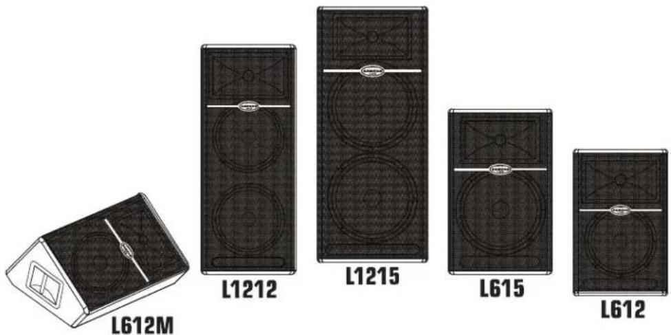
L612 and L615 Layout
- Titanium Compression Driver - 1.75 inch (44mm), titanium diaphragm with 1 inch opening.
- Wide Dispersion Horn - 1 inch throat, 60 × 90 degree wide dispersion horn provides extensive coverage and linear off-axis response.
- Low Frequency Driver - 12-inch and 15-inch woofers with oversize motors and 3-inch voice coils deliver deep, controlled bass response.
- Power LED – Blue Light Emitting Diode illuminates indicating the unit is powered on and ready for operation.
- Handle - One of two over sized carry handles.
- Steel Grill – Durable steel grill provides protection for, and easy access to LF driver.
- Bass Port – A precision tuned, low frequency port, extends the bass response.
- Enclosure – Rigid, all-plywood enclosure for maximum output and durability.
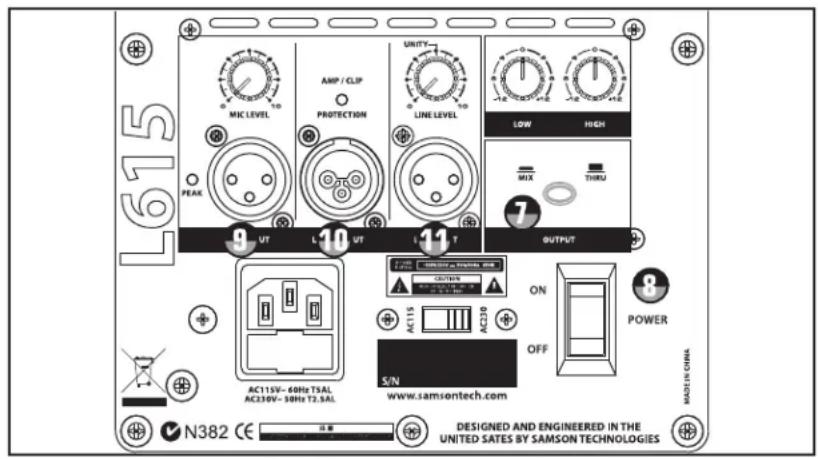
Amplifier Panel Rear View
- Heat sink - Convection cooling of the internal power amplifier via massive aluminum extrusion.
- PEAK LED - LED light to indicate mic input peak.
- MIC LEVEL – Used to adjust the volume of the microphone input.
-
AMP / CLIP LED - Dual color LED lights Green when amp is active, flashes Red when the amp is clipped or stays Red indicating the amplifier is in protect mode.
-
LINE LEVEL – Used to control the level of the line input.
- LOW FREQUENCY - Controls the low band of the Channel Equalizer, +/- 12 dB at 100Hz.
- HIGH FREQUENCY - Controls the high band of the Channel Equalizer, +/- 12 dB at 10kHz.
- OUTPUT switch - This switch is used to select the signal that is sent to the Line Output. When the switch is in the up position, the signal on the Line Output is exactly the same as the signal on the Input. When the switch is in the down position, the Line Output carries the MIX of the Mic and Line Inputs, as well as the High and Low Equalizer.
- POWER – Switches on the LIVE series' main power.
- VOLTAGE switch - Used to change the operating voltage from 115 to 230 volts.
IMPORTANT NOTE! Bure sure to confirm and install the properly rated fuse when changing the operating voltage. (See below AC Power Inlet).
- LINE INPUT connector - XLR Input for connecting balanced line level signals.
- AC Power inlet / Fuse Sled- Connect the supplied standard IEC AC power cable here.
- LINE OUTPUT connector- Male XLR connector used to link multiple LIVE series.
- MIC INPUT connector - XLR Input for connecting low impedance microphones to the Low-Noise pre-amp and Phantom Power.
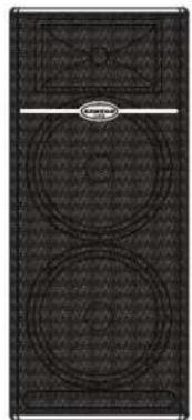
L1212 and L1215 Layout
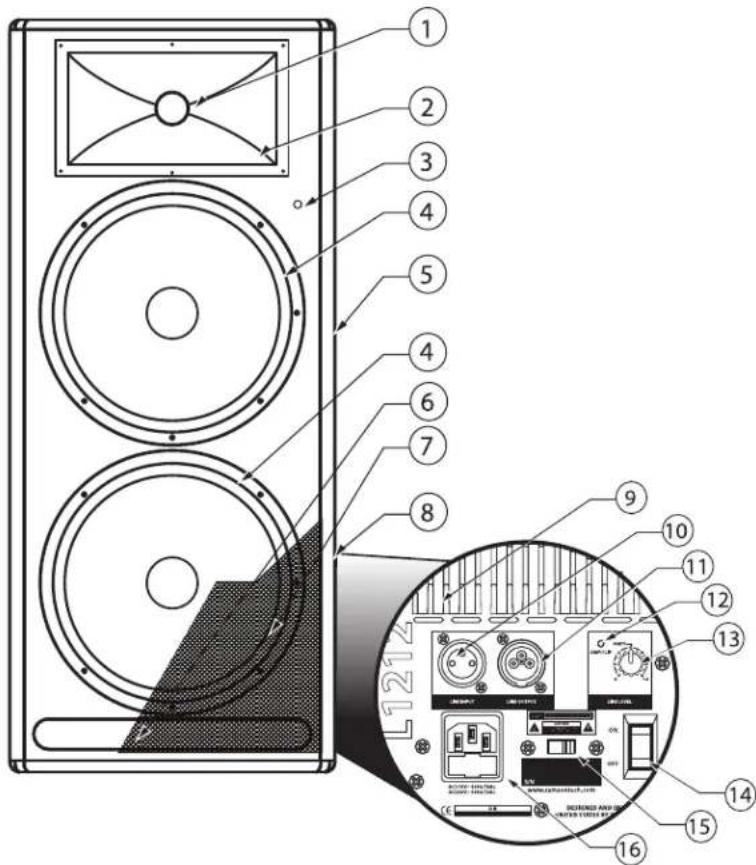
- Titanium Compression Driver - 1.75 inch (44mm), titanium diaphragm with 1 inch opening.
- Wide Dispersion Horn - 1 inch throat, 60 × 90 degree wide dispersion horn provides extensive coverage and linear off-axis response.
- Power LED – Blue Light Emitting Diode illuminates indicating the unit is powered on and ready for operation.
- Low Frequency Driver - 12-inch and 15-inch woofers with oversize motors and large voice coils deliver deep, controlled bass response.
- Handle – One of two over sized carry handles.
- Bass Port– Precision tuned, low frequency port extends the bass response.
- Steel Grill – Durable steel grill provides protection for, and easy access to LF driver.
- Enclosure – Rigid, all-plywood enclosure for maximum output and durability.
Amplifier Panel Rear View
- Heat sink - Convection cooling of the internal power amplifier via massive aluminum extrusion.
- LINE INPUT connector - XLR Input for connecting balanced line level signals.
- LINE OUTPUT connector- Male XLR connector used to link multiple LIVE series.
- AMP / CLIP LED - Dual color LED lights Green when amp is active, flashes Red when the amp is clipped or stays Red indicating the amplifier is in protect mode.
- LINE LEVEL- Used to control the level of the line input.
- POWER – Switches on the LIVE series' main power.
- VOLTAGE switch - Used to change the operating voltage from 115 to 230 volts.
IMPORTANT NOTE! Bure sure to confirm and install the properly rated fuse when changing the operating voltage. (See below AC Power Inlet).
- AC Power inlet / Fuse Sled- Connect the supplied standard IEC AC power cable here.
- Enclosure – Rigid, all-plywood enclosure for maximum output and durability.
- Handle – Oversize carry handle.
- Bass Port– Precision tuned, low frequency port extends the bass response.
- Steel Grill – Durable steel grill provides protection
- Low Frequency Driver - 12-inch woofer with oversize motor and 3-inch voice coil deliver deep, controlled bass response.
- Power LED – Blue Light Emitting Diode illuminates indicating the unit is powered on and ready for operation.
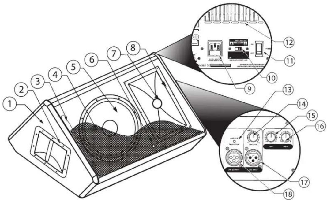
7 Titanium Compression Driver - 1.75 inch (44mm), titanium diaphragm with 1 inch opening. - Wide Dispersion Horn - 1 inch throat, 60 × 90 degree wide dispersion horn provides extensive coverage and linear off-axis response.
Amplifier Panel Rear View
- AC Power inlet / Fuse Sled – Connect the supplied standard IEC AC power cable here.
- VOLTAGE switch - Used to change the operating voltage from 115 to 230 volts.
IMPORTANT NOTE! Bure sure to confirm and install the properly rated fuse when changing the operating voltage. (See above AC Power Inlet).
- POWER – Switches on the L612Ms main power.
- Heat sink - Convection cooling of the internal power amplifier via massive aluminum extrusion.
Amplifier Panel Side Viewv
- AMP / CLIP LED - Dual color LED lights Green when amp is active, flashes Red when the amp is clipped or stays Red indicating the amplifier is in protect mode.
- LINE LEVEL – Used to control the level of the line input.
- LOW FREQUENCY - Controls the low band of the Channel Equalizer, +/- 12 dB at 100Hz.
- HIGH FREQUENCY - Controls the high band of the Channel Equalizer, +/- 12 dB at 10kHz.
- LINE INPUT connector - XLR Input for connecting balanced line level signals.
- LINE OUTPUT connector- Male XLR connector used to link multiple L612M's.
L612 and L615 Quick Set-Up
In the following pages of this manual, you will find a detailed explanation of all the Live Series functions and controls, but if you just want to get started quickly with the L612 and L615 you can follow the steps below.
Using a Microphone
- Be sure that the Live Series Power switch is set to the off position.
- Turn the LINE and MIC LEVEL controls fully counterclockwise to the off position.
- Connect the power cable to an AC socket.
- Using a standard XLR cable, plug a microphone into the Live Series MIC INPUT.
- Switch the Live Series Power switch to the ON position.
- While speaking into the microphone, slowly raise the MIC LEVEL control until you have reached the desired level.
Using a Line Level Signal
- Be sure that the Live Series Power switch is set to the off position.
- Turn the LINE and MIC LEVEL controls fully counterclockwise to the off position.
- Connect the power cable to an AC socket.
- Using a standard XLR cable, connect a line level signal from a mixer or keyboard into the Live Series LINE INPUT.
- Switch the Live Series Power switch to the ON position.
- Now, run an audio signal from your mixer (like some music from a CD) while slowly raising the Live Series LINE LEVEL control until you have reached the desired level.
IMPORTANT NOTE!!: Be sure to keep the MIC LEVEL control all the way off if there is no microphone connected.
IMPORTANT NOTE!!: Be sure to watch the PEAK LED, as it should only light RED occasionally.
Operating the speaker while the PEAK LED stays on RED could cause catastrophic damage to your speaker. So be sure to lower the mixers output or the LINE LEVEL input control until the PEAK LED lights RED only occasionally.
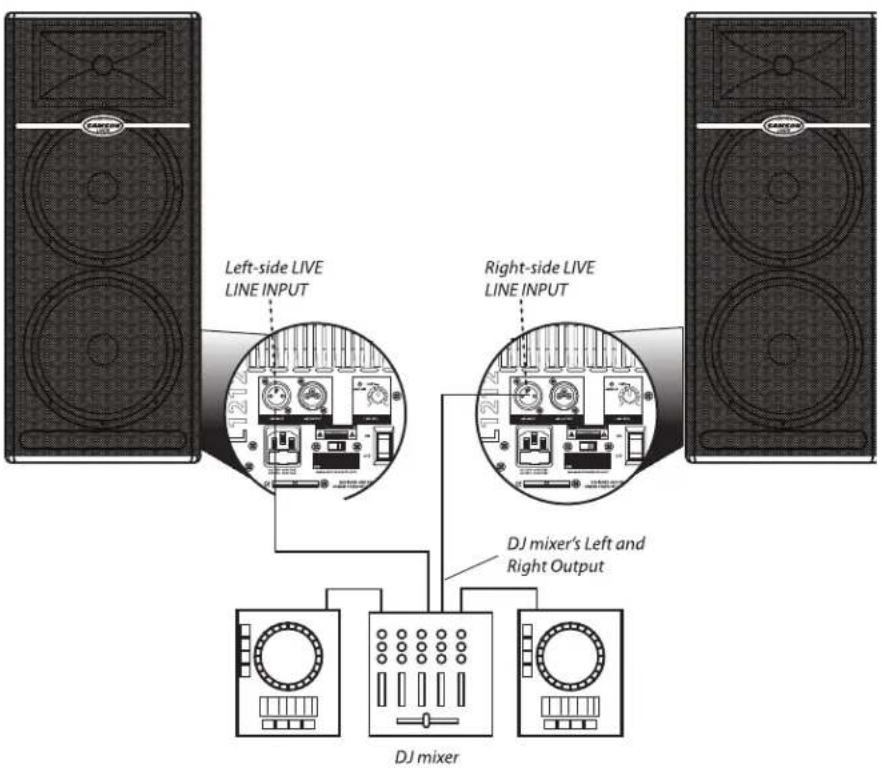
L1212 and L1215 Quick Set-Up
In the following pages of this manual, you will find a detailed explanation of all the Live Series functions and controls, but if you just want to get started quickly with the L1212 and L1215 you can follow the steps below.
Using a Line Level Signal
- Be sure that the Live Series speakers' Power switch is set to the off position.
- Turn the LINE controls fully counterclockwise to the off position.
- Connect the power cables to an AC socket.
- Connect your turntables or CD players to your DJ mixer following the manufacturers instructions.
- Using a standard XLR cable, connect the mixer's left output to the left side Live Series' LINE INPUT and then connect the mixer's right output to the right side LIVE series' LINE INPUT.
- Switch the Live Series Power switch to the ON position.
- Now, run an audio signal (like some music from a CD) from your mixer and check that you are getting a good level using the mixers output meter.
- Next, slowly raise the Live Series LINE LEVEL control until you have reached the desired level.
IMPORTANT NOTE!!: Be sure to watch the PEAK LED, as it should only light RED occasionally. Operating the speaker while the PEAK LED stays on RED could cause catastrophic damage to your speaker. So be sure to lower the mixers output or the LINE LEVEL input control until the PEAK LED lights RED only occasionally.
Positioning the Live Series
Microphone Positioning - How to Reduce Feedback
Feedback is the annoying howling and squealing that is heard when the microphone gets too close to the speaker and the volume is high. You get feedback when the microphone picks up the amplified signal from the speaker, and then amplifies through the speaker again, and then picks it up again, and so on and so on. In general, it is always recommended that any live mic (a mic that's on) is positioned behind the speaker enclosures. This will give you the best level from your system before feedback. One possible exception is when you are adjusting the sounds of the microphones, since you want to listen in front of the speaker to hear properly. To do this, lower your mixers MAIN VOLUME while setting the EQ and effect from in front of the speakers. Once you have the sound you like, move the microphones to behind the speakers and raise the Main volume.
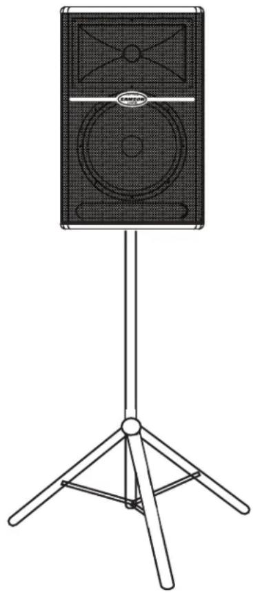
Speaker Placement
Whenever possible, it is a good idea to raise the speakers above the heads of the listening audience. The L612, and L615 enclosures' feature standard 1 3/8" pole mount receptacles, which are compatible with speaker stands from a variety of manufacturers. In a smaller setting (like a school cafeteria, library, or a mall kiosk), you can also use the LIVE series in tilt back monitor positions, which will improve the projection of the speakers and may eliminate the need for speaker stands. For larger settings (like clubs and parties), the L1212 and L1215 can be placed directly on the floor which causes a bass coupling effect that enhances the low frequency response. For even more bass, place a LIVE series on top of a powered sub woofer like the Samson dB1500a or dB1800a.
natural_image
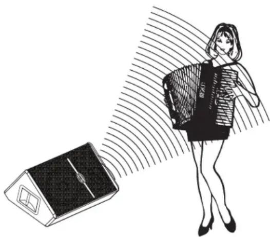
Line drawing of a speaker on a tripod stand (no text or symbols)Positioning the L612M Floor Monitor
The L612M is an ideal solution for stage monitoring and thanks to its unique low-profile design. In a large stage monitor system, several L612M's can be daisy-chained together using the Line Output. When positioning the monitor, be mindful of the placement of your microphones to help reduce feedback problems. It's a really good idea to know your microphone's pick up pattern to choose the right spot. Some microphones, like super and hyper cardioid models, offer a lot of rejection in the rear of their pick up pattern and when the L612M is positioned at the same angle as the rejection, you can set the monitor a lot louder before it feeds back. In many instances when using several L612M's in a monitor system, you may choose to use an external equalizer like the Samson S Curve 131 to increase the volume and reduce the chance of feedback. In this case be sure to set the HIGH and LOW EQ to the 12:00 or flat position.
natural_image
Illustration of a woman holding a device with a device emitting sound waves, next to a solar panel (no text or symbols)Operating the Live Series
Controls and Functions
The following section details each part of the LIVE series INPUT section including the MIC and LINE inputs, the two-band EQ, as well as the MIC and LINE LEVEL controls.
1. MIC LEVEL (L612 and L615 only)
The L612 and L615's MIC LEVEL controls the overall level of the microphone input. Raise the MIC Level to adjust the volume of the microphone connected to the MIC input.
IMPORTANT NOTE!!: Be sure to keep the MIC LEVEL control all the way off if there is no microphone connected.
2. PEAK LED
The PEAK LED will illuminate
RED when the LIVE series Mic
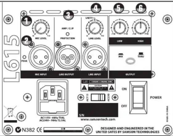
or Line input is receiving a clipped signal. If the PEAK LED lights up, lower the Mic or Line Level control. Once the PEAK LED goes off, raise the level controls back up until just before the PEAK LED lights.
3. DYNAMIC PROTECTION
The AMP / CLIP LED is a dual color LED used to monitor the output of the LIVE Series' internal power amplifiers. When the unit is first powered on, the AMP / CLIP LED will light red (indicating the output relay is open). After the soft-start circuitry activates and the output relay closes, the AMP / CLIP will change to bright green indicating the unit is ready for operation. The LED will flash red on signal power peaks, while the green LED is still on. If there is a failure condition, the output relay opens and the LED will switch to solid red, indicating a fault. If this happens, contact your authorized Samson Audio Service Center.
4. LINE LEVEL
The LIVE Series' LINE LEVEL controls the overall level of the LINE input. Raise the LINE Level to adjust the volume of the signal connected to the LINE input.
Using the Equalizer Section (L612, L612M and L615 only)
The L612, L612M and L615 input channels feature a 2-band equalizer allowing you to adjust the high and low frequencies independently. The channel's frequency response is flat when the knobs are in the "12:00" position. You can set a "music" curve by adding a little boost to both the LOW and HIGH frequency. When using the L612M as a vocal monitor, try a little cut on the LOW and HIGH frequency to remove unwanted bass and treble for a more focused mid-range response. For most applications, it's best to start with the LOW and HIGH controls set flat (12:00 position) and then use the HIGH and LOW EQ in small amounts until you reach the sound you want.
5. LOW
Rotating the LOW knob towards the right will boost the bass frequencies at 100Hz by 12dB, and rotating it towards the left will cut the bass frequencies at 100Hz by 12dB.
6. HIGH
Rotating the HIGH knob towards the right will boost the treble frequencies at 10kHz by 12dB, and rotating it towards the left will cut the treble frequencies at 10kHz by 12dB.
Operating the Live Series
Controls and Functions - continued
7. OUTPUT SWITCH
The Output switch is used to select the signal that is sent to the Line Output. You can have either a parallel output directly from the Line input, or a mixed signal including the Mic and line inputs plus the EQ and limiter. When the switch is in the up position, the signal on the Line Output is exactly the same as the signal on the Line Input. When the switch is in the down position, the Line Output carries the MIX of the Mic and Line Inputs. If
the Level controls, High and Low Equalizer and Filter are used, they will also affect the signal sent to the Line Output.
8. POWER SWITCH
Each Live Series enclosure has a main POWER switch to activate the system. It's a good idea to keep the POWER switch, and INPUT LEVEL controls, set to their off positions before you install the IEC power cable. Connect the supplied AC cable to the AC inlet on the rear amplifier panel. Be sure you have a good AC power connection, and then, set the POWER switch to the "ON" position. The LIVE series amplifiers feature a "soft start" circuit to protect the amplifier from potentially damaging inrush current. In order to ensure that the soft start circuit is working properly, be sure to avoid turning the POWER switch on and off too quickly.
Input and Output Connectors
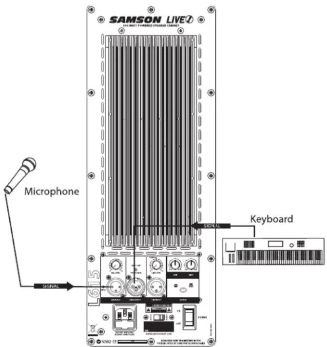
9. MIC XLR Input (L612 and L615 only)
The Live Series' microphone input accepts a standard low impedance (150-600 Ohms) input and the connection is made via a standard female XLR connector. The microphone input features a high quality, discrete transistor pre-amp providing transparency and extended dynamic range. The MIC input can work simultaneously with the LINE input so it is possible to use a microphone while playing alone with a keyboard that is plugged into the Live Series's LINE input. You can control the microphone input by using the MIC LEVEL control as described in the section below.
10. LINE OUTPUT
You can run several cabinets by using the LINE OUTPUT to daisy-chain one Live Series to another. The LINE OUTPUT is a balanced output that, depending on the position of the OUTPUT switch, will have either a direct parallel output of the Line input, or the Mix of the Line and Mic input. For more information on the Output switch, see section 7 above. For more information on cables and wiring, see page 13 of this manual for a detailed wiring diagrams.
11. LINE Balanced Input
The Live Series speakers employ an XLR connector that accepts a standard XLR mic cable for balanced line level signals. The LINE input can work simultaneously with the Mic input so it is possible to use a microphone while playing alone with a keyboard that is plugged into the Live Series's LINE input. You can control the LINE input by using the LINE LEVEL control as described in the previous page. For more information on cable and wiring, see page 13 of this manual for a detailed wiring diagrams.
Live Series System Set-ups
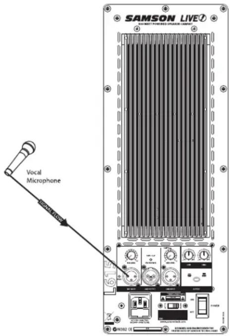
L612 and L615 Compact Lounge PA for Two
This example shows a PA system set-up that can be used for a small club, at a ceremony or in a lounge, using a single Live Series for both a microphone and vocal. A separate signal is sent from the vocal microphone to the L612 or L615's Mic input, and from the keyboard to the Live Series' Line input. The individual Mic and Line level controls allow you to create a mix right on the Live Series. For further control, you can use the Live Series' two-band equalizer to boost or cut the highs and/or low frequencies adjusting the overall tonal contour of the system.
For more information on cable and wiring, see page 13 of this manual for a detailed wiring diagrams.

Live Series System Set-ups
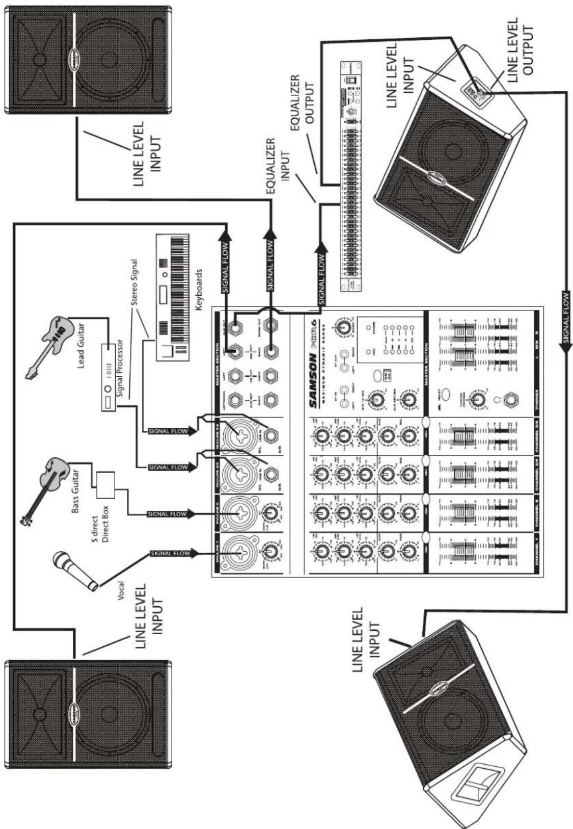
Live Band PA System With Monitors
flowchart
graph TD
    A["Line Level Input"] --> B["Vocal"]
    B --> C["S direct Direct Box"]
    C --> D["Bass Guitar"]
    D --> E["Lead Guitar"]
    E --> F["Signal Processor"]
    F --> G["Stereo Signal"]
    G --> H["Keyboards"]
    H --> I["Line Level Input"]
    I --> J["Line Level Output"]
    J --> K["SIGNAL FLOW"]
    K --> L["EQUALIZER INPUT"]
    L --> M["EQUALIZER OUTPUT"]
    M --> N["SAMSON HDR6 MAXIMUM DYNAMIC LABELS"]
    N --> O["CHANNEL 1 CHANNEL 2 CHANNEL 3 CHANNEL 4 CHANNEL 5 CHANNEL 6 PHONES L MIX R"]
    O --> P["SIGNAL FLOW"]
    P --> Q["LINE LEVEL INPUT"]
    Q --> R["LINE LEVEL OUTPUT"]
    R --> S["SIGNAL FLOW"]
    S --> T["CHANNEL 1 CHANNEL 2 CHANNEL 3 CHANNEL 4 CHANNEL 5 CHANNEL 6 PHONES L MIX R"]
    T --> U["SIGNAL FLOW"]
    U --> V["CHANNEL 1 CHANNEL 2 CHANNEL 3 CHANNEL 4 CHANNEL 5 CHANNEL 6 PHONES L MIX R"]
This example shows a typical PA system using mixer with a pair of Live Series for the main left and right mix. A separate
signal from the mixer's AUX/MONITOR bus is sent to two additional Live Series monitors. In order to increase the output
of the monitor system, the use of an external graphic equalizer like one of the Samson "D Class" or "S curve" series is highly
recommended.
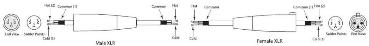
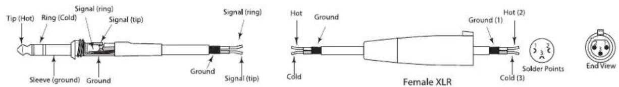
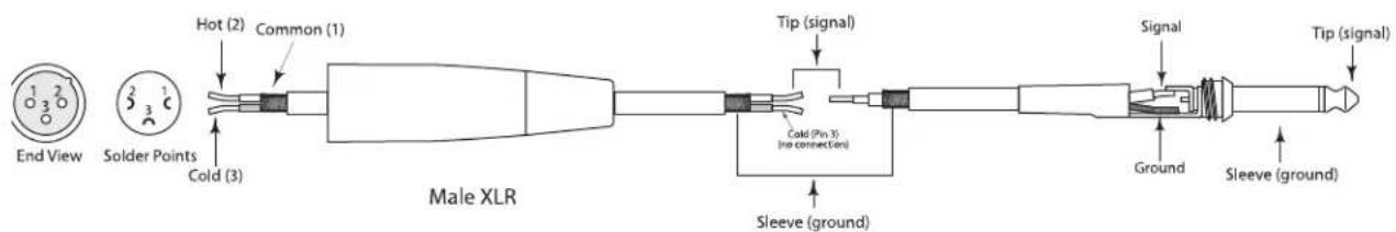
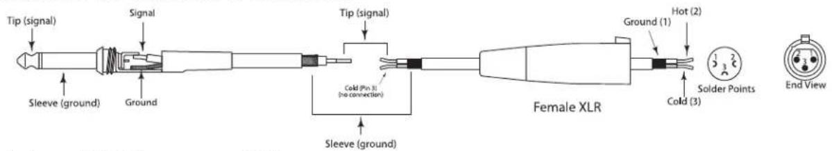
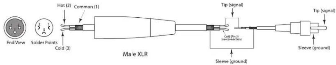
LIVE! Series Wiring Guide
Connecting The Live Series
The are several ways to interface the Live Series to support a variety of applications. The Live Series features balanced inputs and outputs, so connecting balanced and unbalanced signals is possible.
XLR to XLR Balanced
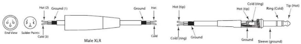
XLR to Balanced 1/4-Inch
Balanced 1/4" Connector to Female XLR
Unbalanced Male XLR to1/4" Connector
Unbalanced 1/4" Connector to Female XLR
Unbalanced XLR Connector to RCA
Introduction
natural_image
Isometric line drawing of a roof-mounted device with ventilation grille and door (no text or symbols)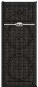
natural_image
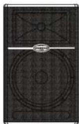
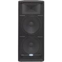
Black-and-white photo of a speaker grille with two circular speakers and a top panel (no text or symbols visible)L1212

L1215

natural_image
Top-down view of a CD or DVD drive with circular and rectangular panels (no visible text or symbols)L615
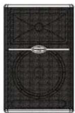
L612
natural_image
Line drawing of a speaker on a tripod stand (no text or symbols)natural_image
Illustration of a woman carrying a device with a fan, standing beside a solar panel (no text or symbols)natural_image
Line drawing of a speaker on a tripod stand (no text or symbols)L612M Bodenmonitor positionieren
natural_image
Illustration of a woman carrying a bag with a phone emitting sound waves from a device (no text or symbols)Live-Serie bedienen
natural_image
Isometric line drawing of a roof-mounted device with ventilation grille and side panel (no text or symbols)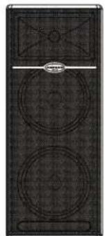
natural_image
Black-and-white photo of a speaker grille with two circular speakers and a top panel (no text or symbols visible)L1212
L1215
natural_image
Top-down view of a CD or DVD drive with circular and rectangular panels (no visible text or symbols)L615

L612
natural_image
Top-down view of a CD-ROM drive with front panel and top screen (no visible text or symbols)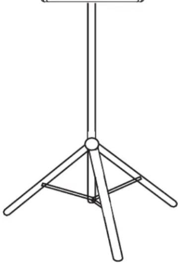
natural_image
Line drawing of a simple tripod stand with three legs and a central hub (no text or symbols)natural_image
Illustration of a woman carrying a bag with a device emitting sound waves, next to a solar panel (no text or symbols)natural_image
Line drawing of a speaker on a tripod stand (no text or symbols)natural_image
Illustration of a woman carrying a bag with a device emitting sound waves, next to a solar panel (no text or symbols)Microphone ....Balanced XLR
Line ....Balanced XLR
Outputs
Extension ....Balanced XLR
Controls
Mic Level .....Rotary
Line Level .....Rotary
Low EQ .....Rotary Center Detent, +/- 12dB @100Hz
High-EQ .....Rotary Center Detent, +/- 12dB @ 10kHz
Output Switch ....Push Switch, Selects Mix or Thru for Line Output Connector
Amplifier
Low Frequency .....250 Watt RMS
High Frequency .....50 Watt RMS
Crossover Frequency ....2.3 kHz,3 pole (12dB Per Octave)
Speakers
LF Driver 12" heavy-duty bass transducer, 3" voice coil
Impedance ....4 ohms
HF Driver ....1.4" titanium compression driver, edgewound copper voice coil, 75 oz. magnet structure
Exit Throat Diameter .....1"
Frequency Response .....55 Hz - 19 kHz, +/- 5dB
Mounting
Stand Integral 1 3/8", Pole Mount Receptacle
Weight 50.11 lbs (22.78 kg)
Dimensions (H x W x D) ....25.19" x 16.14" x 15.74" (640mm x 410mm x 400mm)
L615
Inputs
Microphone ....Balanced XLR
Line ....Balanced XLR
Outputs
Extension ....Balanced XLR
Controls
Mic Level .....Rotary
Line Level .....Rotary
Low EQ .....Rotary Center Detent, +/- 12dB @100Hz
High-EQ .....Rotary Center Detent, +/- 12dB @ 10kHz
Output Switch ....Push Switch, Selects Mix or Thru for Line Output Connector
Amplifier
Low Frequency .....250 Watt RMS
High Frequency .....50 Watt RMS
Crossover Frequency ....2.3 kHz,3 pole (12dB Per Octave)
Speakers
LF Driver 15" heavy-duty bass transducer, 3" voice coil
Impedance .....4 ohms
HF Driver ....1.4" titanium compression driver, edgewound copper voice coil, 75 oz. magnet structure
Exit Throat Diameter 1"
Frequency Response .....52 Hz - 19 kHz, +/- 5dB
Mounting
Stand ....Integral 1 3/8", Pole Mount Receptacle
Weight 52.47 lbs. (23.85 kg.)
Dimensions (H x W x D) ....28.14" x 17.71" x 15.74" (715mm x 450mm x 400mm)
L612M
Inputs
Line Balanced XLR
Outputs
Extension ....Balanced XLR
Controls
Line Level .....Rotary
612M - continued
Low EQ .....Rotary Center Detent, +/- 12dB
@100Hz
High-EQ .....Rotary Center Detent, +/- 12dB @
10kHz
Amplifier
Low Frequency .....250 Watt RMS
High Frequency .....50 Watt RMS
Crossover Frequency ....2.3 kHz,3 pole (12dB Per Octave)
Speakers
LF Driver 12" heavy-duty bass transducer, 3" voice coil
Impedance .....4 ohms
HF Driver ....1.4" titanium compression driver, edge-wound copper voice coil, 75 oz. magnet structure
Exit Throat Diameter 1"
Frequency Response .....56 Hz – 19 kHz, +/- 5dB
Weight 57.46 lbs. (26.12 kg
Dimensions (H x W x D) ....25.19" x 16.14" x 13.97" (640mm x 410mm x 355mm)
L1212
Inputs
Line Balanced XLR
Outputs
Extension ....Balanced XLR
Controls
Line Level .....Rotary
Amplifier
Low Frequency .....400 Watt RMS
High Frequency .....100 Watt RMS
Frequency Response ....58 Hz - 24 kHz ± 5 dB
Crossover Frequency ....2.3 kHz, 3 pole (12dB Per Octave)
Speakers
LF Driver 2x12" heavy-duty bass transducer, 2.5" voice coil
Impedance 8 ohms
HF Driver 1.75" titanium compression driver, edge-wound copper voice coil, 75
oz. magnet structure
Exit Throat Diameter 1'
Frequency Response .....50 Hz - 23 kHz ± 5 dB
Weight 75.81 lbs (34.46 kgs)
Dimensions (H x W x D) ....37.8" x 16.14" x 15.74" (960mm x
410mm x 400mm)
L1215
Input
Line Balanced ....Balanced XLR
Outputs
Extension ....Balanced XLR
Controls
Line Level .....Rotary
Amplifier
Low Frequency .....400 Watt RMS
High Frequency .....100 Watt RMS
Crossover Frequency ....2.3 kHz,3 pole (12dB Per Octave)
Speakers
LF Driver 2x15"heavy-duty bass transducer, 3" voice coil
Impedance ....8 ohms
HF Driver ....1.75" titanium compression driver, edge-wound copper voice coil, 75 oz. magnet structure
Exit Throat Diameter 1"
Frequency Response .....48 Hz - 23 kHz ± 5 dB
Weight 89.97 lbs. (38.17 kg.)
Dimensions (H x W x D) ....43.7" x 18.89" x 15.74" (1110mm x 480mm x 400mm)
Dimensions (H x L x P) .....640 mm x 410 mm x 355 mm
L1212
Entrée
Impédance .....8 Ohms
Dimensions (H x L x P) .....960 mm x 410 mm x 400 mm
L1215
Entrée
Impédance ....8 Ohms
Dimensions (H x L x P) .....1110 mm x 480 mm x 400 mm
L612
Entrées
Dimensions (H x L x P) .....640 mm x 410 mm x 400 mm
L615
Entrées
Dimensions (H x L x P) .....715 mm x 450 mm x 400 mm
L612M
Entrée
Mic ......symmetrisch XLR Line ......symmetrisch XLR
Ausgänge
Extension ......symmetrisch XLR
Regler
Mic ......symmetrisch XLR Line ......symmetrisch XLR
Ausgänge
Extension ......symmetrisch XLR
Regler
Low Frequency .....250 Watt RMS High Frequency .....50 Watt RMS Trennfrequenz .....2.3 kHz, 3-Pol (12dB/Oktave)
Lautsprecher
Line ......symmetrisch XLR
Ausgänge
Extension ......symmetrisch XLR
612M - Fortsetzung
Regler
Line Level ....Drehregler Low EQ ....Drehregler, mittig rast., +/- 12dB @100Hz High-EQ ....Drehregler, mittig rast., +/- 12dB @10kHz
Verstärker
Low Frequency ....250 Watt RMS High Frequency ....50 Watt RMS Trennfrequenz ....2.3 kHz, 3-Pol (12dB/Oktave)
Lautsprecher
Line ......symmetrisch XLR
Ausgänge
Extension ......symmetrisch XLR
Regler
Line Level ......Drehregler
Verstärker
Low Frequency ....400 Watt RMS High Frequency ....100 Watt RMS Frequenzgang ....58 Hz – 24 kHz ± 5 dB Trennfrequenz ....2.3 kHz, 3-Pol (12dB/Oktave)
Lautsprecher
Line ......symmetrisch XLR
Ausgänge
Extension ......symmetrisch XLR
Regler
Line Level ......Drehregler
Verstärker
Low Frequency .....400 Watt RMS High Frequency .....100 Watt RMS Trennfrequenz .....2.3 kHz, 3-Pol (12dB/Oktave)
Lautsprecher
Freq. Basse 250 Watt RMS
Freq. Acute 50 Watt RMS
Dimensioni (A x L x P) ... 64 x 41 x 40 cm (25,19" x 16,14" x 15,74")
L615
Ingressi
Freq. Basse 250 Watt RMS
Freq. Acute 50 Watt RMS
Freq. Basse 250 Watt RMS
Freq. Acute 50 Watt RMS
Freq. Basse 400 Watt RMS
Freq. Acute 100 Watt RMS
Freq. Basse 400 Watt RMS
Freq. Acute 100 Watt RMS

- CAUTION
- Important Safety Instructions
- FRANÇAIS
- Introduction
- Live Series Features
- L612 and L615 Layout
- L1212 and L1215 Layout
- L612 and L615 Quick Set-Up
- Using a Microphone
- Using a Line Level Signal
- L1212 and L1215 Quick Set-Up
- Positioning the Live Series
- Microphone Positioning - How to Reduce Feedback
- Speaker Placement
- Positioning the L612M Floor Monitor
- Operating the Live Series
- Controls and Functions
- MIC LEVEL (L612 and L615 only)
- PEAK LED
- DYNAMIC PROTECTION
- LINE LEVEL
- Using the Equalizer Section (L612, L612M and L615 only)
- LOW
- HIGH
- OUTPUT SWITCH
- POWER SWITCH
- Input and Output Connectors
- MIC XLR Input (L612 and L615 only)
- LINE OUTPUT
- LINE Balanced Input
- Live Series System Set-ups
- L612 and L615 Compact Lounge PA for Two
- LIVE! Series Wiring Guide
- Connecting The Live Series
- L612M Bodenmonitor positionieren
- Live-Serie bedienen
- Outputs
- Controls
- Amplifier
- Speakers
- Mounting
- L615
- Inputs
- L612M
- 612M - continued
- L1212
- L1215
- Input
- Entrée
- L612
- Entrées
- Ausgänge
- Regler
- Lautsprecher
- 612M - Fortsetzung
- Verstärker
- Ingressi
Brand : SAMSON
Model : Live L1215
Category : Loudspeaker