
SGYPM910HL - Meter PIONEER - Free user manual and instructions
Find the device manual for free SGYPM910HL PIONEER in PDF.
| Product Type | Pedaling Monitor Sensor (Left Side) |
| Brand | Pioneer |
| Model | SGY-PM910HL |
| Weight | Approximately 22 g |
| Dimensions (Left Side) | 92.5 mm (W) × 34.7 mm (H) × 8.6 mm (D) |
| Power Supply | CR2032 Battery (pre-installed) |
| Communication | ANT+ wireless (2.4 GHz) |
| Water Resistance | IPX-6 / IPX-7 |
| Operating Temperature | -10 °C to 50 °C |
| Operating Modes | Pedaling Monitor, Dual Force Meter (with right sensor), Single Force Meter |
| Crankset Compatibility | Shimano FC-9000, FC-6800 |
| Key Features | Real-time analysis of pedaling force and efficiency, cadence measurement, vector display |
| Box Contents | Left sensor (strain gauge unit, transmitter), magnets (patch type and arm type), user manual, warranty card, CR2032 batteries, cable ties, pads, magnetic base |
| Settings | Mode change via button on right transmitter or SGX-CA500 cycle computer |
| Calibration | Zero point calibration via cycle computer |
| Troubleshooting | Status LED (green, orange, red) |
| Maintenance | Clean with soft, dry cloth; avoid benzene, thinner; regularly clean battery terminals |
| Storage | Remove batteries if not used for an extended period |
| Warranty | Warranty card included |
| Repairability | Installation and calibration by a dealer; sensor attached with adhesive tape, not removable without damage |
| Certification | ANT+ certified |
Frequently Asked Questions - SGYPM910HL PIONEER
User questions about SGYPM910HL PIONEER
0 question about this device. Answer the ones you know or ask your own.
Ask a new question about this device
Download the instructions for your Meter in PDF format for free! Find your manual SGYPM910HL - PIONEER and take your electronic device back in hand. On this page are published all the documents necessary for the use of your device. SGYPM910HL by PIONEER.
USER MANUAL SGYPM910HL PIONEER
Please read the "Important Information for the User" in the product box for product warnings and other important safety information.
Installing and Removing the Batteries 12
Switching to the pedaling monitor mode 15
Switch to dual power meter mode 19
Switch to single power meter mode 23
Pairing /Calibration
Pairing with the Cyclocomputer 24
Calibrating the sensors (zero point calibration) 26
Specifications and support
Troubleshooting 28
Specifications 31
Care, Maintenance, and Storage 32

This product is ANT+™ certified.
Visit http://www.thisisant.com/director/ for a list of compatible products and apps.
Features
EN
This product is a sensor system that analyzes the pedaling of a bicycle in real time. It calculates the direction and intensity of the force acting on the pedals and calculates pedaling efficiency.
Description of components
- Strain gauge unit :
Detects the strain on the crank and calculates the direction and intensity of the force on the crank.
- Magnet:
Used to detect the angle of rotation.
Transmitters:
Send information from the strain gauge unit and the magnet to the Cyclocomputer.
Product mode
-
When using SGX-CA500, the firmware version is required to be 20150501.02.43 or higher.
-
Pedaling monitor mode:
When paired with Cyclocomputer SGX-CA500, the pedaling efficiency and cadence and other such properties can be measured. You can make maximum use of the functions of this product.
- Dual power meter mode:
Left and right sensors are required. The actual power values of the left and right sensors can be totaled and displayed and the cadence can be measured. Can be used with SGX-CA500 or with a Cyclocomputer that supports ANT+ from another manufacturer.
- Single power meter mode:
The power value of the left or right sensors can be doubled and displayed quickly and the cadence can be measured. Can be used with SGX-CA500 or with a Cyclocomputer that supports ANT+ from another manufacturer.
Switching modes
- When using SGX-CA500, the firmware version is required to be 20150501.02.43 or higher.
- Pedaling monitor mode (Page 15)
Can be switched with SGX-CA500. Cannot be switched with cyclocomputers from other manufacturers. When the mode is switched to pedaling mode, the LEDs on the sensors light green for 10 seconds.
| Current mode | Method 1 (Right sensor push switch) | Method 2 (SGX-CA500) | LED lighting method |
| Dual power meter Cannot be switched | ○ | The LEDs light green for 10 seconds | |
| Single power meter Cannot be switched | ○ | ||
- Dual power meter mode (Page 19)
The mode can be switched on SGX-CA500 or by operating the right sensor push switch. When using with another manufacturer's Cyclocomputer, switch using method 1. When the mode is switched to powermeter mode, the LEDs light orange for 10 seconds.
| Current mode | Method 1 (Right sensor push switch) | Method 2 (SGX-CA500) | LED lighting method |
| Pedaling monitor Cannot be switched | ○ | The LEDs light orange for 10 seconds | |
| Single power meter | ○ | ○ | |
- Single power meter mode (Page 23)
SGX-CA500 is required to switch from pedaling monitor mode. Cannot be switched with cyclocomputers from other manufacturers. To switch from the dual power meter mode, use SGX-CA500 or press the push switch of the right sensor. When the mode is switched, the LEDs on the sensors blink orange for 10 seconds.
| Current mode | Method 1 (Right sensor push switch) | Method 2 (SGX-CA500) | LED lighting method |
| Pedaling monitor Cannot be switched | ○ | The LEDs blink orange for 10 seconds | |
| Dual power meter | ○ | ○ | |
Manuals
The product's manuals consist of this User's Manual, Support Pages, and Important Information for the User.
- User's Manual (this document)
Explains how to switch the modes of the product, and how to pair the product with the Cyclocomputer and calibrate the sensors.
- Support pages (WEB site)
http://pioneer-cyclesports.com/us-en/support/products/ Explains details about handling methods. How to detach the product (for dealers) is also described in the references.
- Important Information for the User
Important Information for the User provides detailed information related to safety.
Compatibility
Crank set
This product supports the following crank sets.
| Crank set Remarks | |
| SHIMANO FC-9000 | Supports 165 / 167.5 / 170 / 172.5 / 175 / 177.5 / 180 mm crank length, and 50-34T / 52-36T / 52-38T / 53-39T / 54-42T / 55-42T crank sets. * |
| SHIMANO FC-6800 | Supports 165 / 170 / 172.5 / 175 mm crank length and 50-34T / 52-36T / 53-39T crank sets. * |
-
This manual explains the crank set of 170 mm length with examples.
-
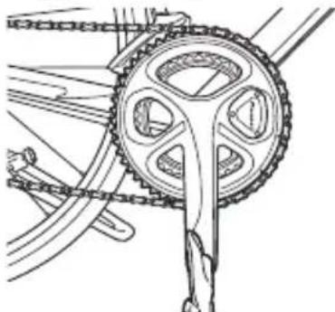
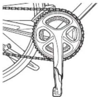
When replacing the chain ring, be careful not to disconnect the junction cable of the right pedaling monitor sensor. See the video on how to remove the chain ring first on http://pioneer-cyclesports.com/us-en/support/products/ to confirm the procedure.
Special skills and tools are needed for the installation and calibration of the product. To install and calibrate, always ask the shop from where you bought the product to do it.
Since the product is attached to the crank set with an adhesive, it cannot be removed without destroying the sensor.
Product Configuration
EN
SGY-PM910H2
This product contains the following parts.
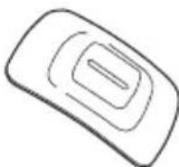
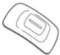
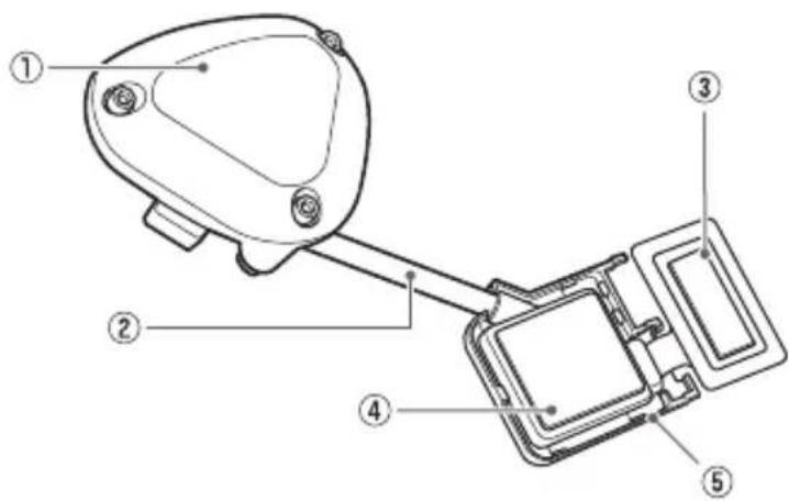
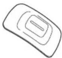
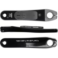
Pedaling monitor sensor (left side)
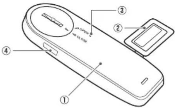
Pedaling monitor sensor part (left side)
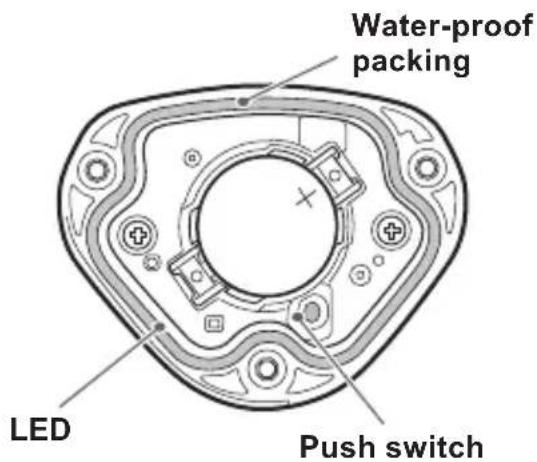
① Left transmitter
② Strain gauge unit
③ LED
④ Device Number
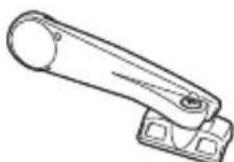
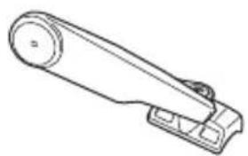
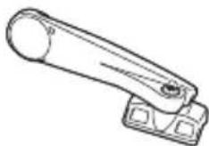
Pedaling monitor sensor (right side)
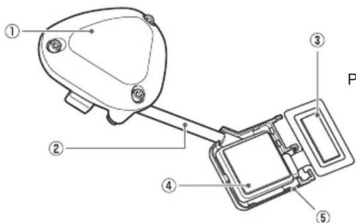
Pedaling monitor sensor part (right side)
① Right transmitter
② Junction cable
③ Strain gauge unit
④ Junction box
Device Number (Described on the back)
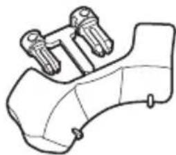
Strain gauge unit cover x 1 for each type

For FC-9000

For FC-6800

Chain ring Adapter
For FC-6800
Adapter base
Magnet
Patch type x 2 Arm type (right side) Arm type (left side)
Others
- User's Manual (this document)
Warranty Card - Batteries (CR2032) x 2 (preinstalled in the sensors)
Right transmitter cover (metallic gray) - Hex screws (M2.6 x 8 mm) x 3 (for the right transmitter x 3)
- Hex screws (M2.6 x 5 mm) x 3 (spare for the right transmitter cover x 3)
- Cable ties x 10 (for the left magnet x 2, for the right magnet x 2, spare x 6)
Cushions for the arm type magnet installation x 2 - Patch type magnet base × 2
- Tape for installing the chain ring adapter
- Tape for installing the FC-6800 adapter base
SGY-PM910HL
This product contains the following parts.
Pedaling monitor sensor (left side)
Pedaling monitor sensor part (left side)
① Left transmitter
② Strain gauge unit
③ LED
④ Device Number
Magnet
Patch type Arm type (left side)
Others
- User's Manual (this document)
Warranty Card - Batteries (CR2032) (preinstalled in the sensor)
- Cable ties x 4 (for the left magnet x 2, spare x 2)
Cushions for the arm type magnet installation - Patch type magnet base
EN
Product Configuration
SGY-PM910HR
This product contains the following parts.
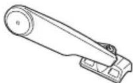
Pedaling monitor sensor (right side)
Pedaling monitor sensor part (right side)
① Right transmitter
② Junction cable
Strain gauge unit
④ Junction box
Device Number (Described on the back)
Strain gauge unit cover x 1 for each type

For FC-9000

For FC-6800

Chain ring Adapter
For FC-6800
Adapter base
Magnet
Patch type Arm type (right side)
Others
- User's Manual (this document)
Warranty Card - Batteries (CR2032) (preinstalled in the sensor)
Right transmitter cover (metallic gray) - Hex screws (M2.6 x 8 mm) x 3 (for the right transmitter x 3)
- Hex screws (M2.6 x 5 mm) x 3 (spare for the right transmitter cover x 3)
- Cable ties × 4 (for the right magnet × 2 , spare × 2 )
- Cushions for the arm type magnet installation
- Patch type magnet base
- Tape for installing the chain ring adapter
- Tape for installing the FC-6800 adapter base
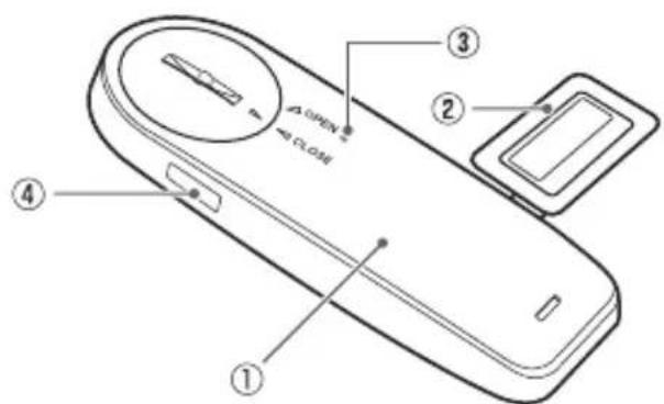
Installing and Removing the Batteries
The batteries are pre-installed to this product. If the batteries are almost empty (see Page 28 for how to confirm), replace the batteries with new ones by the following procedure.
- Replace the batteries of both the left and right sensors at the same time.
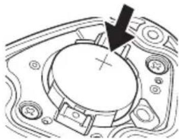
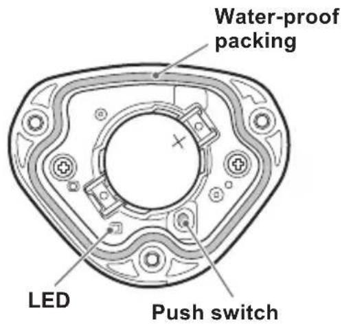
1. Remove the cover.
- Be careful not to drop or lose the battery when removing the cover.
- Right transmitter (screws: 3 × 1 ) Use a hex wrench ( 2 ~mm ) to loosen the screw and remove the cover.

- Be careful not to lose the removed screw.
- Do not lose the water-proof packing.
- Left transmitter
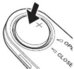
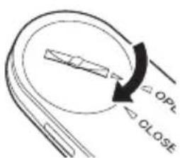
Turn the cover to the left so the triangular arrow points to [OPEN] and remove it.

2. Remove the old battery.
Right transmitter
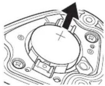
- Left transmitter
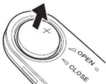
3. Install the new battery (CR2032).
Right transmitter
- Left transmitter
After installing the battery, place the cover with the triangular arrow pointing to [OPEN], and turn it with coin to [CLOSE].
- Be careful not to drop or lose the battery when installing it.
- Do not lose the water-proof packing.
- Do not use batteries other than CR2032. It can cause malfunction.
- Install the cover firmly to ensure water resistant performance.
- Use a dry cotton swab to wipe the battery terminal in the transmitter taking care not to deform the terminal. Clean the terminal regularly to ensure that the transmitter operates steadily.
4. Check the LED display.
The transmitter starts when the batteries are installed. The LEDs of the transmitters light as follows depending on the actual sensor mode.
- When it is in pedaling monitor mode:
The LEDs light green for 10 seconds
- When it is in dual power meter mode:
The LEDs light orange for 10 seconds
- When it is in single power meter mode:
The LEDs blink orange for 10 seconds
- If the LEDs do not light for more than 5 seconds after installing the batteries, remove the batteries once, and after more than 1 minute, install them again. If the LEDs still do not light, the battery may be almost empty. Replace the battery with a new one. Dispose of useless batteries as instructed by the local government.
5. Install the right transmitter cover and tighten the screws to fix it in place.
While tightening the screws, do not use excessive force or over-tighten them. The plastic cover can crack if you do so. Use a tool that can measure the torque to tighten the screws.
-
Tightening torque: 30 cN·m
-
Install the transmitter cover and screw the screws in firmly to ensure water resistant performance.
Switching to the pedaling monitor mode
EN
- Cyclocomputer SGX-CA500 is required to switch to the pedaling monitor mode. The mode cannot be switched with cyclocomputers from other manufacturers.
-
The firmware version of SGX-CA500 needs to be 20150501.02.43 or higher. If it is of a different version, update the firmware. Refer to the User's Guide (For WEB) of SGX-CA500 regarding how to update or any other operation method. http://pioneer-cyclesports.com/us-en/support/products/
-
Press the menu button on the CycloMeter screen of SGX-CA500.
- Tap [Option] - [Pedaling settings] - [Mode Switch] in this order.
The mode switching screen opens. If the device number is already displayed, confirm that it is the same as the device number of the sensor you want to use. If it is the same, the input operation is not required.
If the device number is different from the sensor you want to use, enter the new number.
Remove the check from the sensors whose mode is not to be switched.
- Tap on the device number display part.
The sensor device number input screen opens.
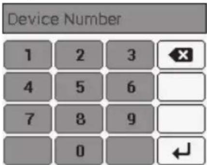
- Enter the device number and tap [ ]
The device numbers are printed on the right junction box and on the side of the left sensor. (Page 7)
-
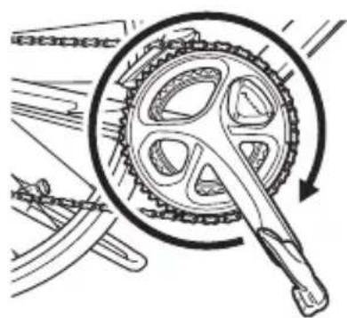
Rotate the bicycle's crank set more than three rotations to start the left and right transmitters.
-
Pair with the Cyclocomputer within 5 minutes after the transmitters are activated.
- Tap [Pedaling Monitor].
The search for the sensor starts. A [Please wait.] message appears.
It may take more than 1 minute to to pair with the sensor.
The mode switching completion screen opens. Tap OK if you want to add in the sensor list.
If you do not add the sensor in the sensor list, the SGX-CA500 will not pair with the sensor.
You can add the sensor in the sensor list later, using the [Sensors] menu.
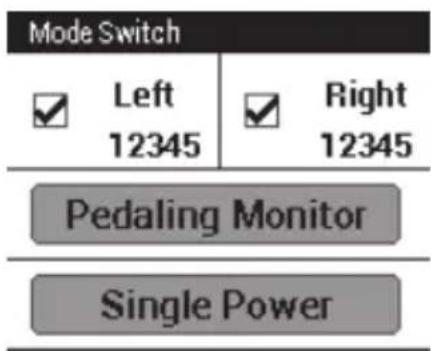
Mode Switch
L:Success
R:Success
Add sensors to the list?
Cancel
OK
When the mode is switched, the LEDs of the sensors light green for 10 seconds.
Add in the sensor list of SGX-CA500
When it is added in the sensor list, it pairs with SGX-CA500.Hereafter, whenever the sensor is started, it will automatically pair with SGX-CA500.
To confirm the sensor list, press the menu button on the left of the product on the main screen of the CycloMeter and tap [Sensors]. The display on the mode switching completion screen is as follows depending on the status.
[Success]
Mode is switched.
- [Timeout]
Sensor is not found.
- [Cancel]
Cancel is pressed.
[Low Battery]
The battery is almost empty.
-
Timeout: Communication status is likely to be poor. Sensor information cannot be received properly. Make sure that the sensor you are pairing is activated, then bring the SGX-CA500 closer to the sensor and perform the pairing operation again. Pairing with the sensor may not be possible due to interference in the same frequency band. If "Timeout" is displayed even by operating after moving SGX-CA500 closer to the sensor and pairing with it, try again someplace where there is no interference from microwaves, radio waves, or wireless equipment.
-
Low Battery: The battery is almost empty. Remove the battery and replace with a new one. For how to install/remove batteries, refer to Page 12.
Copy pedal
Copy pedal is enabled only in pedaling monitor mode.
If only the sensor on one side is operating, you can copy the data on the other side also to display it for both sides on the Cyclocomputer and record it in the log. You can select copy pedal of the current bike and set the balance.
- Press the menu button on the CycloMeter screen.
- Tap [Option] then [Pedaling settings] and then [Pedaling Copy].
| →Bike 4 (Power) | |
| Pedaling Copy | Disable |
| L:R Balance | 49:51 |
- Tap [Pedaling Copy], and select the copy method.
| Pedaling Copy | |
| Disable | ◎ |
| Copy L to R | ○ |
| Copy R to L | ○ |
- To change the balance, tap [L:R Balance].
- Tap [+] , [-] and change the numerical value and tap [OK].
| L:R Balance | |
| + | + |
| 50 | 50 |
| - | - |
| Cancel | OK |
If you set left and right incorrectly, note that the correct power will not be displayed.
Switch to dual power meter mode
- Both the left and right sensors are required in this mode. Cyclocomputer SGX-CA500 is required when the sensor changes to the pedaling monitor mode. It cannot be switched by using cyclocomputers from other manufacturers.
- The firmware version of SGX-CA500 needs to be 20150501.02.43 or higher. If it is of a different version, update the firmware. Refer to the User's Guide (For WEB) of SGX-CA500 regarding how to update.
http://pioneer-cyclesports.com/us-en/support/products/
The mode can be switched in two ways.
[Method 1] Switch by pushing the push switch in the right transmitter
- When using a Cyclocomputer from another manufacturer, switch with this method.
1. Loosen the screws on the right transmitter cover and remove the cover.
Refer to Page 12 to remove the right transmitter cover.
2. Replacing the batteries of the left and right transmitters.
Refer to Page 12 regarding how to install/remove batteries.
- The operation is enabled for 5 minutes after the batteries are installed. Switch within 5 minutes. If more than 5 minutes elapse, reinstall the batteries of the left and right sensors.
When the batteries are installed, the LEDs on the left and right transmitters light as follows depending on the actual sensor mode.
- When it is in pedaling monitor mode:
The LEDs light green for 10 seconds
- When it is in dual power meter mode:
The LEDs light orange for 10 seconds
- When it is in single power meter mode:
The LEDs blink orange for 10 seconds
4. Switch the sensor mode.
- Before switching the mode, confirm that there is no other pedaling monitor near by. If this is not done at a sufficient distance away from other sensors, the other sensors are likely to malfunction.


Push for more than 3 seconds
The LEDs blink green


Move away
The LEDs blink orange rapidly

Confirm that the LEDs on left and right transmitters are blinking

Push for more than 3 seconds
Finished
The LEDs light orange

Failure
The LEDs blink red

By pushing the push switch in the right transmitter for more than 3 seconds, the LEDs on the right transmitter blink green. When communication with the left transmitter is enabled, the LEDs on the left and right transmitters rapidly blink orange.
Confirm that the LEDs on the left and right transmitters blink when the mode is switched. (If they do not blink, the communication may have been done with another pedaling monitor sensor by mistake. Move somewhere away from the other bicycles and do the operation again.)
While the blinking takes place rapidly for 10 seconds, push the switch again during that time for more than 3 seconds. The mode is switched to the dual power meter mode. When the mode is switched, the LED starts lighting orange for 10 seconds. If you do not push long while the LEDs are rapidly blinking orange, it is canceled and so, you must do the operation again.
- It may take several seconds to switch the sensor mode depending on the radio transmission conditions.
If the pairing with the left transmitter fails, the LEDs of the right transmitter blink red 5 times. Since the left transmitter may be in the pedaling monitor mode, switch to the single power meter mode first on Cyclocomputer SGX-CA500 and do the above operation. If it still fails, remove the batteries from the left and right transmitters, wait for more than one minute. Place the batteries back and do the operation again.
After the mode is switched, install the right transmitter cover and tighten the screws to fix it in place. Use a tool that can measure the torque to tighten the screws.
-
Tightening torque: 30cN · m
-
Install the transmitter cover and the screws in firmly to ensure water resistant performance.
- Do not lose the water-proof packing.
For how to pair with the cyclocomputer, when using SGX-CA500, refer to Page 24 and if using a cyclocomputer from another manufacturer, refer to the User's Manual of that cyclocomputer.
[Method 2] Switch the mode on SGX-CA500
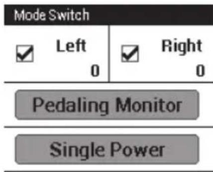
Do operations 1 to 5 described on Page 15 to Page 16, and go to the mode switching screen.
1. If the left and right sensors are checked, tap [Dual Power].
![PIONEER SGYPM910HL - If the left and right sensors are checked, tap [Dual Power]. - 1](/content/2026/02/373801/images/4e623517b5f918ee848d3e6490b6c2f76d56d8b59b9aa79cd86070e67de5362e.jpg)
The mode switching completion screen opens.
![PIONEER SGYPM910HL - If the left and right sensors are checked, tap [Dual Power]. - 2](/content/2026/02/373801/images/d4c478ea83eb36e7ef6678d1f0ed71d6e95f5fc183c0c513d40d3339e38c130c.jpg)
In this state, the cyclocomputer is still not paired with the sensor. Refer to Page 24 regarding how to pair.
If the mode cannot be switched, refer to Add in the sensor list of SGX-CA500 in page 17.
When the mode is switched, the LEDs of the sensors light orange for 10 seconds.
Switch to single power meter mode
- If the actual sensor mode is pedaling monitor mode, switch it on SGX-CA500.
- The firmware version of SGX-CA500 needs to be 20150501.02.43 or higher. If it is of a different version, update the firmware. Refer to the User's Guide (For WEB) of SGX-CA500 regarding how to update. http://pioneer-cyclesports.com/us-en/support/products/
The mode can be switched in two ways. Select according to the actual sensor mode.
[Method 1] Switch by pushing the push switch in the right transmitter
- When using a Cyclocomputer from another manufacturer, switch with this method.
- When it is in the dual power meter mode, if the left and right transmitters are not started, the mode cannot be switched to the single power meter mode.
Rotate the crank set of the bicycle and start the sensor. (Described on Page 16)
When it is in dual power meter mode, if you push the push switch in the right transmitter for more than 3 seconds, the mode changes to single power meter mode and the LEDs blink orange for 10 seconds.
When the LEDs blink red, the left transmitter may not have started. Start it again.
When the sensor is in pealing monitor mode, it does not change to the single power meter mode, even on pushing the the push switch. Switch using method 2.
[Method 2] Switch the sensor mode from SGX-CA500
If the mode is pedaling monitor mode or dual power meter mode, switch using the SGX-CA500. Do the operation as described on Page 15, and go to the mode switching screen. Check the sensor you want to use, then select single power and switch the mode.
For how to pair with the cyclocomputer, refer to Page 24. When the mode is switched, the LEDs of the sensors blink orange for 10 seconds.
Pairing with the Cyclocomputer
This section describes how to pair the installed pedaling monitor sensors on your bicycle to the SGX-CA500 Cyclocomputer.
- If you are using this product with a Cyclocomputer from another manufacturer, the method of pairing is different. Refer to the User's Manual of the Cyclocomputer you are using.
1. Check the sensor modes.
The actual sensor mode can be confirmed from the way the LEDs of the sensors light when the batteries are installed, or from the way the LEDs light on switching to each mode.
Refer to Page 15 to switch the modes.
2. Tap the [Sensors] icon in the home screen of the SGX-CA500.
The sensor list screen opens.
3. Rotate the bicycle's crank set more than three rotations to start the transmitters.
After the transmitters are activated, it may take more than 1 minute to pair with the Cyclocomputer.
- Pair with the Cyclocomputer within 5 minutes after the transmitters are activated.
4. Tap [Connect New] in the sensor list screen of the SGX-CA500.
The sensor connection menu opens.
5. Tap [Device Type] and then [Pedaling Monitor R].
- For the left transmitter, tap [Pedaling Monitor L].
- In single or dual power meter mode, select the device type.
- If multiple sensors are activated, bring the main unit closer to the sensor, or specify the device number to pair the sensor you want to pair. Refer to the User's Guide (For WEB) of the Cyclocomputer SGX-CA500 regarding how to specify a device number to pair a sensor.
6. Tap [Search].
The search for the sensor starts. A [Searching. Please wait.] message appears.
7. Check the information about the sensor.
Information about the sensors appears when the sensors are found.
Check the following items.
- [Device Number]
Make sure that the device number is the same as the device number of the transmitter.
[Error Rate]
Make sure that "OK" is displayed.
| Pedaling Monitor R |
| Device Number 64 |
| Manufacturer Number 48 |
| Error Rate OK |
- The device numbers are printed on the right junction box and on the side of the left sensor. If the numbers that are displayed on (Page 7)[Device Number] are different from the transmitter device numbers, specify the device numbers to pair with the sensor. Refer to the User's Guide (For WEB) of the Cyclocomputer SGX-CA500 regarding how to specify a device number to pair a sensor.
- If "Processing..." is displayed in the [Error Rate] area, the information from the sensor is not being received correctly because transmission conditions are bad. Make sure that the sensor you are pairing is activated, then bring the SGX-CA500 closer to the sensor and perform the pairing operation again.
- Pairing with the sensor may not be possible due to interference in the same frequency band. If "Processing..." is displayed even if the SGX-CA500 is moved closer to the sensor and paired with it, try again someplace where there is no interference from microwaves, radio waves, or wireless equipment.
Pairing of the right transmitter is completed. Pair the left transmitter in the same way.
Calibrating the sensors (zero point calibration)
This section describes how to use the Cyclocomputer to calibrate the zero point of the pedaling monitor sensor that is installed on the bicycle. Zero point calibration is a function to store the zero point (no-load), where no forces act on the crank, in the sensor memory. The accuracy of the sensor improves with repeated implementation.
Zero point calibration should be done by customers whenever the measurement value is deviating.
- The right-side pedaling monitor sensor is used as an example in this description. The procedure to calibrate the left side is the same as for the right side.
- Please do not push the push switch in the right transmitter while calibrating the sensor with the Cyclocomputer.
Calibration method in pedaling monitor mode using SGX-CA500
Getting Started
- Stop the bicycle on a flat safe place.
Calibrating the Zero Point
- Position the crank arm so it is perpendicular to the ground, pointing downward.
- Tap the [Sensors] icon in the home screen of the SGX-CA500.
The sensor list screen opens.
-
Tap [Pedaling Monitor R] and then [Calibration (Zero)].
-
Tap [Start Calibration].
The calibration starts. If the calibration is successful, "Success" appears in the [Result] field. If "Failure" is displayed, the sensor may be calibrated in an unstable condition causing the crank to be moving during the calibration. Calibrate again with the crank in a stable position.
- This product has a correction function for the zero point fluctuation caused by varying temperatures. The accuracy of this function improves by calibrating the sensor when there is a difference in temperature of more than 4^ .
This function cannot measure correctly if you calibrate the sensor before it is acclimated to the outside temperature. The sensor requires more than 20 minutes to become acclimated.
Checking the Zero Point
1. Position the crank arm so it is perpendicular to the ground, pointing downward.
2. Tap [Pedaling Monitor R] in the sensor list screen of the SGX-CA500.
3. Confirm the value in [Force Preview].
Make sure that the [Tangential Force] and [Radial Force] values are as shown here.
Tangential Force: 0 ± 3N
- Radial Force: 0 ± 3N
| Force Preview | |
| Tangential Force | ON |
| Radial Force | ON |
Calibration of the right side is finished. Calibrate the left side in the same way.
Calibration method in power meter mode using a cyclocomputer from another manufacturer
For how to calibrate, refer to the User's Manual of the cyclocomputer you are using.
Troubleshooting
Refer to the following suggestions if you have any problems installing or using the product.
If you cannot find what you want to know here, ask the shop where you bought the product.
I cannot pair with the Cyclocomputer.
| Cause Solution | |
| The battery is almost empty.(Battery voltage target is 2.5V or less) | If the LEDs do not light for more than 5 seconds after installing the batteries, remove the batteries once, and after more than 1 minute, install them again. If the LEDs still do not light, the battery may be almost empty.Replace the battery with a new one. |
| (+) or (−) side of the battery is installed in the opposite side. | Install the battery in the proper side (Page 12). |
| There are other 2.4 GHz wireless equipment or microwave ovens near by. | Move away from other wireless equipment or microwave ovens. Move the sensor closer to the Cyclocomputer and pair them. |
| Another sensor is paired with the Cyclocomputer. | Move away from other sensors by more than 10 m or specify the device number to pair the Cyclocomputer.Refer to the Installation Manual (For Web) for details.http://pioneer-cyclesports.com/us-en/support/products/ |
| Transmitter is not starting. Reinstall | the battery of the transmitter or rotate the bicycle's crank set more than three rotations to start the transmitter. The transmitter will start in 5 minutes, so you must pair in that time.If the problem is not resolved by the above, confirm the magnet installation status from the shop where you bought the product. |
- Unable to switch to pedaling monitor mode.
| Cause Solution | |
| You are not using cyclocomputer SGX-CA500. | You cannot switch to the pedaling monitor mode if you are using some other manufacturer's cyclocomputer. Use SGX-CA500. For how to operate, refer to Page 15. |
| The version of the firmware of SGX-CA500 is old. | Update firmware to 20150501.02.43 or to a higher version. |
- Unable to switch to dual power meter mode.
| Cause Solution | |
| You are not operating the right transmitter push switch correctly. | By pushing the push switch in the right transmitter for more than 3 seconds, the LEDs on the right transmitter blink green. When communication with the left transmitter is enabled, the LEDs on the left and right transmitters rapidly blink orange. As it blinks for 10 seconds, push the switch again for more than 3 seconds to switch. |
| More than 5 minutes have elapsed after the battery was inserted. | To operate by the push switch in the right transmitter, insert the battery and do the above operation within 5 seconds after that. |
| You have paired with another pedaling monitor sensor. | When the LEDs on your left and right transmitters are not blinking orange, it is likely that they are paired with another pedaling monitor sensor by mistake. Move somewhere away from other bicycles and do the above operation again. |
The power value of the pedaling monitor sensor is abnormal.
| Cause Solution | |
| The battery terminal is dirty. | Use a dry cotton swab to wipe the battery terminal in the transmitter taking care not to deform the terminal. Even if it does not appear to be dirty, white dust may be lodged in the battery terminal. Clean the terminal as the problem will be improved if the dust is wiped out. Clean the terminal regularly to ensure that the transmitter operates stably. |
| Battery terminal |
Troubleshooting
Vector display is strange.
| Cause Solution | |
| Magnet is not calibrated. Get the mag- net calibrated from the shop where you purchased the product. Contact with the shop where you purchased the product. |
Zero point calibration fails.
| Cause Solution | |
| The crank is subjected to external force or moving. | Calibrate the sensor in still condition (Page 26). |
The Cyclocomputer display is not displaying correctly while I am riding.
| Cause Solution | |
| Zero point calibration has failed. | Calibrate the sensor if the values in [Force Preview] are more than ± 4N (Page 26). |
There is a rattling noise when I am riding.
| Cause Solution | |
| Screws used to install the right sensor are loose. | Retighten the screws. |
The magnet is rubbing against the sensor or transmitter while I am riding.
| Cause Solution | |
| Foreign objects are attached to the magnet and rub against the transmitter or the junction box. | Clean the transmitter, junction box, and magnet. |
Specifications
EN
Weight : SGY-PM910H2 right side + left side About 62 g
: SGY-PM910HL left side About 22 g
: SGY-PM910HR right side About 40 g
Dimensions : right side
Right transmitter
58.3 mm(W) × 46.1 mm(H) × 21.3 mm(D)
- Junction box, Strain gauge unit cover
78 mm(W) × 36.7 mm(H) × 7.3 mm(D)
: left side
92.5 mm(W) × 34.7 mm(H) × 8.6 mm(D)
Water resistant : This device has a water resistance rating of IPX- 6/IPX- 7
Communications method (sensors): ANT+ wireless
Batteries : CR2032
Operation temperature: -10^ to 50^
- ANT+ is a Wireless Personal Network protocol with very low power requirements using 2.4 GHz frequency band.
For more information, visit http://www.thisisant.com/.
- Specifications and design are subject to change without notice.
- Illustrations used in this manual may be different from actual appearance.
Care, Maintenance, and Storage
Care, Maintenance, and Storage
- Use a soft dry cloth or a cloth that has been dampened and wrung out to wipe dirt from the left and right transmitters, the strain gauge unit cover, the magnet, and other accessories.
- Do not use benzene, paint thinner, or other volatile chemicals, cleansers, or chemically treated cloths. Doing so could damage the product or cause the paint to peel off.
- If any detergent is lodged in around the body of the sensor, wash it off properly with water.
- If you are not going to use the product for a long period of time, remove the batteries.
- Clean the battery terminal regularly to ensure that the transmitter operates steadily. (refer to Page 29.)
Inhalt
Einführung
Funktionen 35
Kompatibilität 38
Erste Schritte
http://pioneer-cyclesports.com/de/support/products/
- Ondersteuningspagina's (website)
http://pioneer-cyclesports.com/nl/support/products/
http://pioneer-cyclesports.com/nl/support/products/
http://pioneer-cyclesports.com/it/support/products/
http://pioneer-cyclesports.com/it/support/products/
http://pioneer-cyclesports.com/us-en/support/products/
PIONEER ELECTRONICS (USA) INC.
P.O. Box 1540, Long Beach, California, 90801-1540, U.S.A.
TEL: (800) 421-1404
PIONEER ELECTRONICS OF CANADA INC.
340 Ferrier Street, Unit 2, Markham, Ontario, L3R 2Z5, Canada
TEL: 1-877-283-5901
TEL: 905-479-4411
PIONEER EUROPE NV
Haven 1087, Keetberglaan 1, B-9120 Melsele, Belgium/Belgique
TEL: +32 (0)3 570 05 11
© 2015 PIONEER CORPORATION.
©2015 PIONEER CORPORATION.
All rights reserved.


- Pairing /Calibration
- Specifications and support
- Features
- Description of components
- Product mode
- Switching modes
- - Pedaling monitor mode (Page 15)
- - Dual power meter mode (Page 19)
- - Single power meter mode (Page 23)
- Manuals
- - User's Manual (this document)
- - Support pages (WEB site)
- - Important Information for the User
- Compatibility
- Crank set
- Product Configuration
- SGY-PM910H2
- Pedaling monitor sensor (left side)
- Pedaling monitor sensor (right side)
- Magnet
- Others
- SGY-PM910HL
- SGY-PM910HR
- Installing and Removing the Batteries
- Remove the cover.
- - Left transmitter
- Remove the old battery.
- Right transmitter
- Install the new battery (CR2032).
- Check the LED display.
- Install the right transmitter cover and tighten the screws to fix it in place.
- Switching to the pedaling monitor mode
- Mode Switch
- Add in the sensor list of SGX-CA500
- Copy pedal
- Switch to dual power meter mode
- [Method 1] Switch by pushing the push switch in the right transmitter
- Loosen the screws on the right transmitter cover and remove the cover.
- Replacing the batteries of the left and right transmitters.
- Switch the sensor mode.
- [Method 2] Switch the mode on SGX-CA500
- If the left and right sensors are checked, tap [Dual Power].
- Switch to single power meter mode
- [Method 2] Switch the sensor mode from SGX-CA500
- Pairing with the Cyclocomputer
- Check the sensor modes.
- Tap the [Sensors] icon in the home screen of the SGX-CA500.
- Rotate the bicycle's crank set more than three rotations to start the transmitters.
- Tap [Connect New] in the sensor list screen of the SGX-CA500.
- Tap [Device Type] and then [Pedaling Monitor R].
- Tap [Search].
- Check the information about the sensor.
- Calibrating the sensors (zero point calibration)
- Getting Started
- Calibrating the Zero Point
- Checking the Zero Point
- Position the crank arm so it is perpendicular to the ground, pointing downward.
- Tap [Pedaling Monitor R] in the sensor list screen of the SGX-CA500.
- Confirm the value in [Force Preview].
- Calibration method in power meter mode using a cyclocomputer from another manufacturer
- Troubleshooting
- Specifications
- Care, Maintenance, and Storage
- Inhalt
- Einführung
- Erste Schritte
- - Ondersteuningspagina's (website)
- PIONEER ELECTRONICS (USA) INC.
- PIONEER ELECTRONICS OF CANADA INC.
- PIONEER EUROPE NV
Brand : PIONEER
Model : SGYPM910HL
Category : Meter