
CYPA2003N - Car stereo PANASONIC - Free user manual and instructions
Find the device manual for free CYPA2003N PANASONIC in PDF.
| Product type | Car radio |
| Brand | Panasonic |
| Model | CYPA2003N |
| Standard dimensions | 1-DIN (178 x 50 mm) |
| Weight | Approximately 0.5 kg |
| Power supply | 12 V DC (vehicle) |
| Radio functions | RDS, AM/FM, auto search |
| CD player | Yes, compatible with CD-R/RW |
| Auxiliary input | Front AUX input (3.5 mm) |
| USB port | Yes, for MP3/WMA playback |
| Bluetooth | No (model without Bluetooth) |
| Output power | 4 x 20 W (max) |
| Display | Backlit LCD |
| Maintenance and cleaning | Soft dry cloth, avoid solvents |
| Safety | Protection fuse (5A) |
| Spare parts available | Wiring harness, optional remote control |
| Reparability | Reparability index not communicated |
| General information | User manual provided, 82 pages |
Frequently Asked Questions - CYPA2003N PANASONIC
User questions about CYPA2003N PANASONIC
0 question about this device. Answer the ones you know or ask your own.
Ask a new question about this device
Download the instructions for your Car stereo in PDF format for free! Find your manual CYPA2003N - PANASONIC and take your electronic device back in hand. On this page are published all the documents necessary for the use of your device. CYPA2003N by PANASONIC.
USER MANUAL CYPA2003N PANASONIC
Operating Instructions
Bedienungsanleitung
natural_image
Black-and-white photo of a tree-lined road lined with dense foliage, no visible text or signage- Please read these instructions carefully before using this product and keep this manual for future reference.
- Bitte lesen Sie diese Bedienungsanleitung vor der Verwendung dieses Produktes aufmerksam durch und bewahren Sie sie danach für spätere Nachschlagzwecke sorgfältig auf.
- Prière de lire ces instructions attentivement avant d'utiliser le produit et garder ce manuel pour l'utilisation ultérieure.
- Si prega di leggere attentamente queste istruzioni prima di usare questo prodotto e di conservare questo manuale per usi futuri.
- Laa con atención estas instrucciones antes de utilizar el producto y guarde este manual para poderlo consultar en el futuro,
Safety Information
Read the operating instructions for the unit and all other components of your car audio system carefully before using the system. They contain instructions about how to use the system in a safe and effective manner. Panasonic assumes no responsibility for any problems resulting from failure to observe the instructions given in this manual.

Warning
This pictograph intends to alert you to the presence of important operating instructions. Failure to heed the instructions may result in severe injury or death.
This manual uses pictographs to show you how to use the product safely and to alert you to potential dangers resulting from improper connections and operations. The meaning of the pictographs are explained below. It is important that you fully understand the meanings of the pictographs in order to use this manual and the system properly.

Caution
This pictograph intends to alert you to the presence of important operating instructions. Failure to heed the instructions may result in injury or material damage.
Please follow the laws and regulations of your province or country for installation of the unit.
This unit cannot be used alone.
This unit is a power amplifier for use with Panasonic car audio products and speakers.
For more details about safety information, refer to the operating instructions for the connected devices
For power connection, use the optional power cord specially designed for use with Panasonic car-audio/AV system.
Power cord kit (option): CA-PAC75

Warning
Observe the following warnings when using the unit.
□Use the proper power supply.
This product is designed for operation with a negative grounded 12 V DC battery system. Never operate this product with other battery system, especially a 24 V DC battery system.
☐Do not disassemble or modify the unit.
Do not disassemble, modify the unit or attempt to repair the product yourself. If the product needs to be repaired, consult your dealer or an authorised Panasonic Service Centre.
Do not use the unit when it is out of order.
If the unit is out of order (no power, no sound) or in an abnormal state (has foreign objects in it, is exposed to water, is smoking, or smells), turn it off immediately and consult your dealer.
Refer fuse replacement to qualified service
personnel.
When the fuse blows out, eliminate the cause and have it replaced with the fuse prescribed for this unit by a qualified service engineer. Incorrect replacement of the fuse may lead to smoke, fire, and damage to the product.
When replacing one fuse which has blown, replace other fuses at the same time.
In some cases, fuses may deteriorate without failing. Using different substitutes or fuses with higher ratings, or connecting the unit directly without a fuse, could cause fire or damage to the unit. If the replacement fuse falls, contact your nearest Panasonic Service Centre for service.

Warning
Observe the following warnings when installing. ...Disconnect the lead from the negative (—) battery terminal before installation.
Wiring and installation with the negative (−) battery terminal connected may cause electrical shock and injury due to a short circuit.
Some cars equipped with the electrical safety
system have specific procedures of battery terminal disconnection.
FAILURE TO FOLLOW THE PROCEDURE MAY
LEAD TO THE UNINTENDED ACTIVATION OF THE ELECTRICAL SAFETY SYSTEM RESULTING IN DAMAGE TO THE VEHICLE AND PERSONAL INJURY OR DEATH.
Never use safety-related components for
Installation, grounding, and other such functions. Do not use safety-related vehicle components (fuel tank, brake, suspension, steering wheel, pedals airbags, etc.) for wiring or fixing the product or its accessories.
Check for piping, gasoline tank, electric wiring, and other items before installing the product.
If you need to open a hole in the vehicle chassis to attach or wire the product, first check where the wire harness, gasoline tank, and electric wiring are located. Then open the hole from outside if possible.
After installation and wiring, you should check the
normal operation of other electrical equipment. The continuation of their using in abnormal conditions
may cause fire, electrical shock or a traffic accident.
in the case of installation to an airbag-equipped car, confirm warnings and cautions of the vehicle manufacturer before installation.
Make sure the leads do not interfere with driving or getting in and out of the vehicle.
Failure to need this caution may result in an accident and/or injury.

Caution
Observe the following cautions when using this unit.
Turn off the power supply before changing the switch setting.
□Keep the sound volume at an appropriate level.
Keep the volume level low enough to be aware of road and traffic conditions while driving.
This unit is designed for use exclusively in
automobiles.
☐Do not operate the unit for a prolonged period with the engine turned off.
Operating the audio system for a long period of time with the engine turned off will drain the battery.
☐Do not expose the unit to direct sunlight or excessive heat.
Otherwise these will raise the interior temperature of the unit, and it may lead to smoke, fire, or other damage to the unit.
☐Do not use the product where it will be exposed to water, moisture, or dust.
Exposure of the unit to water, moisture, or dust may lead to smoke, fire, or other damage to the unit. Make especially sure that the unit does not get wet in car washes or on rainy days.
☐Stop to use the unit when the red indicator (PROTECT) lights up.
If the red indicator lights up, this unit will automatically shut down. Confirm the speaker and other audio system's wiring.
☐ Do not touch the heat dissipation region of the amplifier.
If this unit is operated at a high output continuously, the upper side of the unit will get very hot. Do not touch it nor place anything on top of the unit.
Contact your local dealer for information about
battery capacity. (If there is not enough battery capacity, increase the number of batteries.) Depending on the way you use this unit, (using at high volume for extended periods, increasing the number of amplifiers etc.) there may be insufficient battery capacity. There is a danger that the battery will run fl at, or other electronic parts may stop operating.
☐Do not knock anything against this unit when
Loading or unloading objects from the trunk. Doing so will cause damage to this unit.
Safety Information (continued)

Caution
Observe the following cautions when installing. Refer wiring and installation to qualified service personnel.
Installation of this unit requires special skills and experience. For maximum safety, have it installed by your dealer. Panasonic is not liable for any problems resulting from your own installation of the unit.
☐Follow the instructions to install and wire the product. Not following the instructions to properly install and wire the product could cause an accident or fire.
Take care not to damage the leads.
Prevent them from getting caught in the vehicle chassis, screws, and moving parts such as seat rails. Do not scratch, pull, bend or twist the leads. Do not run them near heat sources or place heavy objects on them. If leads must be run over sharp metal edges, protect the leads by winding them with vinyl tape or similar protection.
Use the designated parts and tools for installation. Use the supplied or designated parts and appropriate tools to install the product. The use of parts other than those supplied or designated may result in internal damage to the unit. Faulty installation may lead to an accident, a malfunction or fire.
Do not install the product where it is exposed to strong vibrations or is unstable.
Avoid slanted or strongly curved surfaces for installation. If the installation is not stable, the unit may fall down while driving and this can lead to an accident or injury.
We strongly recommended you to wear gloves for installation work to protect yourself from injuries. Failure to heed this caution may result in an accident and/or injury.
Be sure to grip both sides of this unit securely before attempting to move it.
Since this unit is quite heavy, the unit may fall down and this can lead to an accident or injury.
Cover the unused terminals with insulating tape to prevent them from short circuiting.
When an extension lead is used, it should be as thick and short as possible; connect it firmly with insulating tape.
Wire breaks and short circuits can cause electrical shock or fire.
Use the spacer included when installing the unit so that the fan and air hole on the base side of the unit are not covered.
If the fan and air hole on the base side of the unit are covered, the unit will become extremely hot and may fail.
Caution for mounting the unit:
Never mount the unit in any of the following locations to avoid damage due to overheating;
• Near the heater port
- Places like the dashboard or rear deck, where it may be exposed to direct sunlight.
Do not mount the unit near the door, where it could be exposed to rain.
Keep a safe distance between the unit and other electronic equipment.
When a short circuit occurs, such as in the speaker output terminal, etc. the overload protection circuit will operate. This circuit protects the power amplifier from further damage when a short circuit occurs. Operation will temporarily stop. In this case, check the cause of the short-circuit and if the problem is fixed, normal operation will resume.
Since the power amplifier has a very large output, the unit should be installed in the trunk of your car. Do not install this unit under a carpet, otherwise the unit may fail because of immature heat dissipation. In case more than one power amplifier is used, make sure to employ the power cord and the fuse having the current capacity larger than the total current corresponding to the maximum consumption powers of all the amplifiers.
Caution for the power cord (option):
Follow an expert's instruction for the use of the cord separately sold.
For the power, make sure to use the battery lead (yellow) separately sold and specially designed for Panasonic car-audio/AV system, and to connect directly to the car battery. Use the cord having the fuse capacity larger than that of this unit. Connect the power cord and other cords corresponding to the power supply after all the connections to the speaker are completed.
□Keep the battery lead (yellow) away from the speaker cord.
☐ Make sure to use the ground lead (black) separately sold and specially designed for car audio system, and to connect it to the metal portion of the car chassis.
Wire the battery lead (yellow), the ground lead (black), the speaker cords, and this unit with as much distance as possible from the antenna, the antenna cords and the car stereo (car radio).
☐ If the ground wire is common to both left/right and front/rear speaker wirings, this unit cannot be used. Always use the independent lead wire for the speakers to be used. In this case, redo the wiring.
Caution for the speaker cord (option):
☐The speaker cords and the power amplifier unit should be kept away from the antenna and antenna extension cord.
☐Do not directly ground the speaker cords; do not share the negative leads of multiple speakers.
When using the RCA cords, keep away from the speaker cords.
Caution for the speaker (option):
☐ Use speakers with a suitable maximum input. ☐ In case of 4-channel/3-channel connection
Use speakers with the impedance of 2-8 Ω.
□In case of 2-channel/stereo connection:
Use speakers with the impedance of 4-8 Ω.
Information on Disposal for Users of Waste Electrical & Electronic Equipment (private households)


This symbol on the products and/or accompanying documents means that used electrical and electronic products should not be mixed with general household waste.
For proper treatment, recovery and recycling, please take these products to designated collection points, where they will be accepted on a free of charge basis. Alternatively, in some countries you may be able to return your products to your local retailer upon the purchase of an equivalent new product.
Disposing of this product correctly will help to save valuable resources and prevent any potential negative effects on human health and the environment which could otherwise arise from inappropriate waste handling. Please contact your local authority for further details of your nearest designated collection point. Penalties may be applicable for incorrect disposal of this waste, in accordance with national legislation.
For business users in the European Union
If you wish to discard electrical and electronic equipment, please contact your dealer or supplier for further information.
Information on Disposal in other Countries outside the European Union
This symbol is only valid in the European Union. If you wish to discard this product, please contact your local authorities or dealer and ask for the correct method of disposal.
Before Reading These Instructions
Panasonic welcomes you to our constantly growing family of electronic products owners. We endeavor to give you the advantages of precise electronic and mechanical engineering, manufactured with carefully selected components, and assembled by people who are proud of the reputation their work has built for our company. We know this product will bring you many hours of enjoyments, and after you discover the quality, value and reliability we have built into it, you too will be proud to be a member of our family.
CY-PA4003N
4 Channel Power Amplifier
CY-PA2003N
2 Channel Power Amplifier
CY-PAD1003N
Digital Mono Amplifier
Differences among 3 Models
This Operating Instruction manual is for 3 models CY-PA4003N, CY-PA2003N and CY-PAD1003N. All illustrations throughout this manual represent model CY-PA4003N unless otherwise specified. The following table describes the differences among 3 models.
| Features\Models | CY-PA4003N CY-PA2003N CY-PAD1003N | ||
| Speaker connection | 4/3/2-channel speaker | 2/1-channel speaker | 1-channel speaker |
| Maximum power output | 250 W×4 channel | 600 W×2 channel | 1 100 W×1 channel |
| Input channel | 4-channel | 2-channel | 2-channel |
| 4CH/2CH input selection | Yes | No | No |
| HPF (High Pass Filter) | Yes | Yes | No |
| Subsonic filter switch | No | No | Yes |
| Fuse | 35 A×2 | 25 A×3 | 25 A×3 |
| Speaker input connector | 2 (1 for front speaker, 1 for rear speaker) | 1 (for left/right speaker) | 1 (for left/right speaker) |
Accessories
| Item Diagram | Qty. | |
| Operating Instructions (YEFM2B5831A) | 1 | |
| PAN EUROPEAN GUARANTEE (Warranty Card) | 1 | |
| Installation Hardware (screws, cords, etc.) (page 20) | ||
Note:
- The number in parenthesis underneath each accessory part name is the part number for maintenance and service.
- Accessories and their parts numbers are subject to modification without prior notice due to improvements.
Before Use
- Check the connections according to the manual of the device you have connected, and switch on the connected device's power supply.
- Adjust the GAIN to a satisfactory volume. (page 11, 12)
- Refer to individual instruction and installation manuals for each device for detailed installation and wiring.
Contents
| English | 2 |
| Deutsch | 34 |
| Français | 66 |
| Italiano | 98 |
| Español | 130 |
Safety Information 2
Before Reading These Instructions ... 6
Before Use 7
Features......8
Location of Controls 10
Speaker System Setting
Speaker System Setting
Speaker System Setting
Note for Bridge Speaker Connection .... 19
Installation....20
Wiring 22
Wiring
RCA 24 SPEAKERS INPUT 25
Wiring
RCA 26
SPEAKERS INPUT 27
Wiring
RCA....28 SPEAKERS INPUT....29
Troubleshooting....30
Maintenance....32
Specifications 32
Features
CY-PA4003N
250 W × 4 channel maximum power output
Total 1000 W maximum power output
An amplifier connected to the 4-, 3- or 2-channel speaker
2CH/4CH input selection:
The 4-channel speaker output is available under the 2-channel speaker input setting.
Low-Pass Filter for subwoofer, High Pass Filter:
Switchover of LPF/OFF/HPF is available.
CY-PA2003N
600 W × 2 channel maximum power output
Total 1 200 W maximum power output
Low-Pass Filter for subwoofer, High Pass Filter:
Switchover of LPF/OFF/HPF is available.
CY-PAD1003N
1 100 W × 1 channel maximum power output
Low-Pass Filter for subwoofer:
Switchover of LPF/OFF is available.
High Level Speaker Input connection:
The high-quality playback sound is produced when connecting the unit to the speaker output lead of the Head Unit.
Use It when the Head Unit is not equipped with the terminal for the RCA output lead.
Bass boost control system:
The bass boost circuit is employed to play back the deep bass on the front and rear speakers.
Crossover Frequency Control:
The frequency band in the treble and the bass, which are played back on the front and rear speakers, can be adjusted.
RCA output terminals:
Equipped with RCA output for adding a power amplifier.
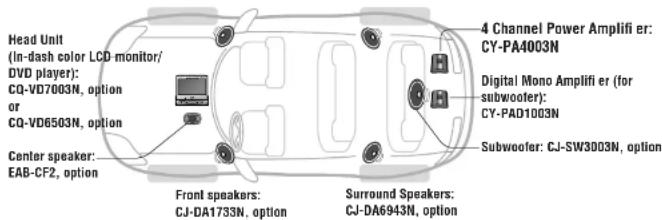
5.1-channel Surround System (Combination with other Panasonic car audio products)
You can enjoy a powerful 5.1-channel surround system by connecting Head Unit (CQ-VD7003N, CQ-VD6503N, option), 4-channel amplifier (CY-PA4003N) and monaural amplifier for subwoofer (CY-PAD1003N). For more details, refer to the operating instructions for the connected devices.
text_image
Head Unit (In-dash color LCD monitor/ DVD player): CQ-VD7003N, option or CQ-VD6503N, option Center speaker: EAB-CF2, option Front speakers: CJ-DA1733N, option Surround Speakers: CJ-DA6943N, option 4 Channel Power Amplifier: CY-PA4003N Digital Mono Amplifier (for subwoofer): CY-PAD1003N Subwoofer: CJ-SW3D03N, optionLocation of Controls
text_image
BN> 1 2 3 4 5 6 7 8 9 10 11 12 For channel A (except ②) For channel B (except ③) SPEAGERS RJW PFEER CHMP TRELLA RJW TRELLA RJW TRELLA RJW TRELLA RJW TRELLA RJW TRELLA RJW TRELLA RJW TRELLA RJW TRELLA RJW TRELLA RJW TRELLA RJW TRELLA RJW
Caution
- Turn off the power supply before changing the switch setting.
- Stop to use the unit when the red indicator (PROTECT) lights up.
If the red indicator lights up, this unit will automatically shut down. Confirm the speaker and other audio system's wiring.
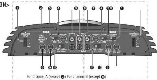
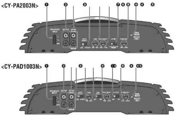
① High level speaker input terminal (SPEAKERS INPUT)
When connecting Head Unit without RCA output terminals.
2 Power/protection indicator (PWR/PROTECT) Lights green: When the Head Unit power is on. Lights red;
- When the speaker cords are short-circuited.
- When the speaker output line comes contact with the car grounding wire.
- When this unit falls and the speaker output generates a DC power source.
- When the amplifier internally creates a high-pitched sound.
- When the connection of the Head Unit or this unit is not completed.
③ Crossover filter switch (LPF, OFF, HPF)
LPF (Low Pass Filter): LPF cuts off the treble, and outputs only a low-pitched sound for the subwoofer. OFF: All frequency bands are output without filtering. Select when a subwoofer is not connected. HPF (High Pass Filter): Sound is output from the speakers for a high-pitched sound and midrange sound after deleting the low-pitched sound.
④ Crossover frequency control knob (FREQUENCY)
The frequency band of the treble and the bass played back on the front and rear speakers is adjusted. Setting range: 50 Hz to 250 Hz
⑤ Speaker output terminals (For CH A)
Equipped with RCA output for adding a power amplifier. It is not a Speaker input terminal.
⑤ Channel A input terminals (LEFT, RIGHT)
⑦ Channel B input terminals (LEFT, RIGHT)
⑧ Speaker channel select switch (4CH, 2CH)
4CH: When connecting Head Unit with 2 preout leads. 2CH: When connecting Head Unit with 1 preout lead.
text_image
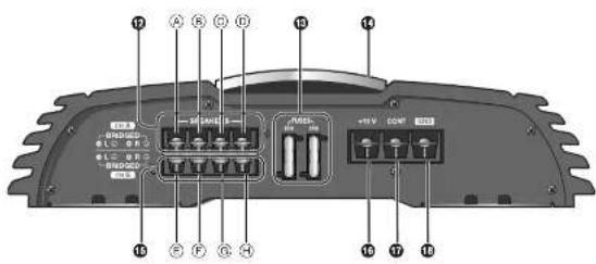
Labeled diagram of a device rear panel with numbered ports and connectorsBASS BOOST control knob
Turn this knob to boost the 45 Hz frequency sound. It enhances the low-pitched sound.
For some speakers, the sound may be distorted because of the excessive power input to them. In that case, turn down the bass level until the distortion stops.
Setting range: 0 dB to 15 dB
10 GAIN control knob
In some instances, the acoustical output from each speaker may not be balanced properly depending upon the type of speakers or Head Unit being used.
Up: Turn up the knob when the sound volume is not satisfactory even though the volume of the Head Unit is increased.
Down: Turn down the knob when the sound is distorted.
⑪ Input select switch (LINE, SPEAKERS)
LINE: When using RCA INPUT connectors. SPEAKERS: When using SPEAKER INPUT connectors.
⑫ Channel A speaker output connector (SPEAKERS)
(A) Left Side (+)
⑥ Left Side (—)
© Right Side (+)
⑥ Right Side (−)
⑬ Fuses (FUSES) (35 A×2)
⑭ Upper cover
⑮ Channel B speaker output connector (SPEAKERS)
E Left Side (+)
Left Side (−)
⑤ Right Side (+)
⑧ Right Side (−)
⑬ Battery connector (+12 V)
To the car battery, continuous +12 V DC.
⑰ Amplifi er control connector (CONT)
To the head unit's external amplifier control power lead or to the car battery, continuous +12 V DC.
18 Ground connector (GND)
To a clean, bare metallic part of the car chassis.
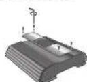
The upper cover can be reinstalled along with the reinstallation of the main body of the unit, such that the cover is aligned with other devices for neat and better look.
How to dismount: Unscrew the terminal screw with Allen wrench ③.
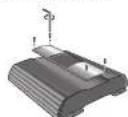
Note:
- Do not insert anything between the upper cover and this unit. Doing so will cause damage to this unit.
Location of Controls (continued)

Caution
- Turn off the power supply before changing the switch setting.
- Stop to use the unit when the red indicator (PROTECT) lights up.
If the red indicator lights up, this unit will automatically shut down. Confirm the speaker and other audio system's wiring.
① High level speaker input terminal (SPEAKERS INPUT)
When connecting Head Unit without RCA output terminals.
② Speaker output terminals
Equipped with RCA output for adding a power amplifier.
It is not a Speaker input terminal.
③ Speaker input terminals (LEFT, RIGHT)
④ Input select switch (LINE, SPEAKERS)
LINE: When using RCA INPUT connectors. SPEAKERS: When using SPEAKER INPUT connectors.
⑤ GAIN control knob
In some instances, the acoustical output from each speaker may not be balanced properly depending upon the type of speakers or Head Unit being used.
Up: Turn up the knob when the sound volume is not satisfactory even though the volume of the Head Unit is increased.
Down: Turn down the knob when the sound is distorted.
BASS BOOST control knob
Turn this knob to boost the 45 Hz frequency sound. It enhances the low-pitched sound. For some speakers, the sound may be distorted because of the excessive power input to them. In that case, turn down the bass level until the distortion stops.
Setting range: 0 dB to 15 dB
⑦ Crossover 11 Iter switch (LPF, OFF, HPF)
LPF (Low Pass Filter): LPF cuts off the treble, and outputs only a low-pitched sound for the subwoofer. OFF: All frequency bands are output without filtering. Select when a subwoofer is not connected.
HPF (High Pass Filter): Sound is output from the speakers for a high-pitched sound and midrange sound after deleting the low-pitched sound.
B Crossover frequency control knob (FREQUENCY)
The frequency band of the treble and the bass played back on the front and rear speakers is adjusted. Setting range: 50 Hz to 250 Hz
⑨ Power/protection indicator (PWR/PROTECT)
Lights green: When the Head Unit power is on. Lights red:
- When the speaker cords are short-circuited.
- When the speaker output line comes contact with the car grounding wire.
- When this unit falls and the speaker output generates a DC power source.
- When the amplifier internally creates a high-pitched sound.
- When the connection of the Head Unit or this unit is not completed.
⑩ Speaker output connector
Ⓐ Left Side (+) Ⓐ SP (+)
(B) Left Side (−) (B) SP (+)
(C) Right Side (+) (C) SP (+)
① Right Side (+) ② SP (−)
③ Right Side (−) ④ SP (−)
⑪ Fuses (FUSES) (25 A×3)
⑫ Upper cover
⑬ Battery connector (+12 V)
To the car battery, continuous +12 V DC.
⑭ Amplifi er control connector (CONT)
To the head unit's external amplifier or control power lead or to the car battery, continuous +12 V DC.
15 Ground connector (GND)
To a clean, bare metallic part of the car chassis.
⑬
Subsonic II Iter switch (OFF, ON)
Switch ON to remove noise from subwoofer.
The upper cover can be reinstalled along with the reinstallation of the main body of the unit, such that the cover is aligned with other devices for neat and better look.
How to dismount:
Unscrew the terminal screw with Allen wrench ③.
Note:
- Do not insert anything between the upper cover and this unit. Doing so will cause damage to this unit.
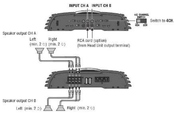
Speaker System Setting
4CH Input
4-channel Speaker System
text_image
INPUT CH A INPUT CH B 4/2 CHANNEL 1/2CH SWITCH Switch to 4CH. Speaker output CH A Left (min. 2 G) Right (min. 2 G) RCA cord (option) (from Head Unit output terminal) Speaker output CH B Left (min. 2 G) Right (min. 2 G)3-channel Speaker System
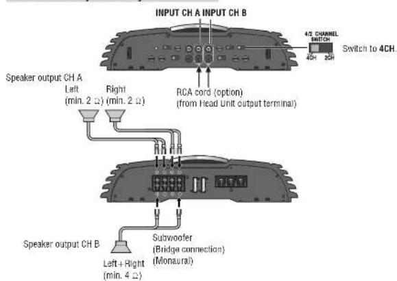
text_image
INPUT CH A INPUT CH B 4/5 CHANNEL SNITCH Switch to 4CH. Speaker output CH A Left (min. 2 Ω) Right (min. 2 Ω) RCA cord (option) (from Head Unit output terminal) Speaker output CH B Left + Right (min. 4 Ω) Subwoofer (Bridge connection) (Monaural)CY-PA4003N/PA2003N/PAD1003N
2-channel Speaker System (Monaural)
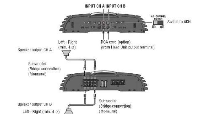
text_image
INPUT CH A INPUT CH B 4Ω CHANNEL SWITCH Switch to 4CH. RCA cord (option) (from Head Unit output terminal) Left + Right (min. 4 Ω) Speaker output CH A Subwoofer (Bridge connection) (Monaural) Speaker output CH B Left - Right (min. 4 Ω) Subwoofer (Bridge connection) (Monaural)2-channel Speaker System (Stereo)
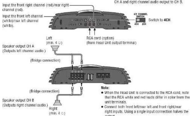
text_image
Input the front right channel (red)/rear right channel (red). Input the front left channel (white)/rear left channel (white). CH A and right channel audio output to CH B. 4/2 CHANNEL SWITCH Switch to 4CH. Left (min. 4 °C) (RCA cord (option) (from Head Unit output terminal) Speaker output CH A (Outputs left channel audio.) (Bridge connection) {Bridge connection} Speaker output CH B (Outputs right channel audio.) Right (min. 4 °C) Note: • When the Head Unit is connected to the RCA cord, note that the RCA while and red leads differ in color from the unit terminals. • Connect both front left/rear left and front right/rear right inputs. Using a single input connection halves the output.CY-PA4003N/PA2003N/PAD1003N
Speaker System Setting (continued)
2CH Input
4-channel Speaker System
text_image
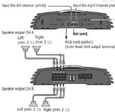
Input the left channel (white). Input the right channel (red) Speaker output CH A Left (min. 2 c) Right (min. 2 c) Not used. RCA cord (option) (from Head Unit output terminal) Speaker output CH B Left (min. 2 o) Right (min. 2 o)Special Application
Example: If the Head Unit only has a single pre-out, connect it to this unit for 4-channel audio output.
Note:
● The fader control is ineffective.
- The speaker outputs A and B are at the same level
■ The 3-channel speaker output is not allowed with the 2-channel input connection.
- When the Head Unit is connected to the RCA cord, note that the RCA white and red leads differ in color from the unit terminals.
2-channel Speaker System
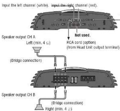
text_image
Input the left channel (white). Input the right channel (red). Speaker output CH A Left (min. 4 Ω) (Bridge connection) Speaker output CH B (Bridge connection) Right (min. 4 Ω) Not used. RCA cord (option) (from Head Unit output terminal)Special Application
Example: If the Head Unit only has a single pre-out, connect it to this unit for 2-channel audio output.
Note:
• This is not a monaural output.
■ The 3-channel speaker output is not allowed with the 2-channel input connection.
- When the Head Unit is connected to the RCA cord, note that the RCA white and red leads differ in color from the unit terminals.
CY-PA4003N/PA2003N/PAD1003N
Speaker System Setting
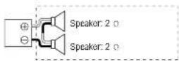
2-channel Speaker System (Stereo)
text_image
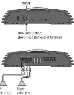
INPUT RCA cord (option) (from Head Unit output terminal) Right (min. 2 C) Right (min. 2 C)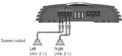
text_image
Speaker output Left (min. 2 c) Right (min. 2 c)1-channel Speaker System (Monaural)
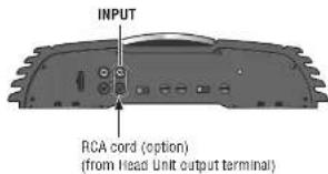
text_image
INPUT RCA cord (option) (from Head Unit output terminal)Speaker output
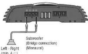
text_image
Left - Right (min. 4 c) Subwoofer (Bridge connection) (Monaural)CY-PA4003N/PA2003N/PAD1003N
Speaker System Setting
2-channel (Monaural) Speaker System
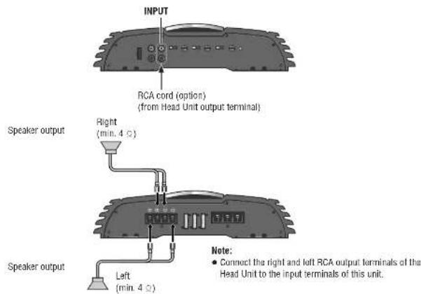
text_image
INPUT RCA cord (option) (from Head Unit output terminal) Speaker output Right (min. 4 Ω) Speaker output Left (min. 4 Ω) Note: ● Connect the right and left RCA output terminals of the Head Unit to the input terminals of this unit.1-channel (Monaural) Speaker System
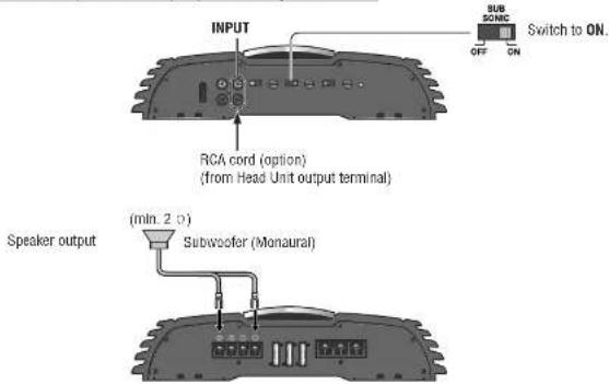
text_image
INPUT RCA cord (option) (from Head Unit output terminal) Speaker output (min. 2.0) Subwoofer (Monaural) SUB SONIC OFF ON Switch to ON.Note for Bridge Speaker Connection
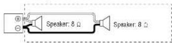
• In case of 2-channel/stereo connection:
in case of multiple speakers to be mounted in a bridge
connection, confirm the summed impedance to be 4–8
Ω in order to avoid ignition, smoking, or damage.
Total impedance: 4 Ω
Total impedance: 4 Ω
Do not make a connection in such a manner.
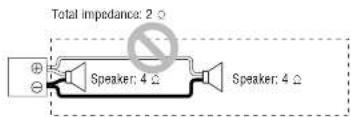
text_image
Total impedance: 2 Ω Speaker: 4 Ω Speaker: 4 ΩNote for RCA Input Connection:
- Selectively assign each front and rear output to either RCA INPUT A or B, in accordance with the system from which the output is coming.
- In case of a single line coming from the RCA output of Head Unit, connect the line to RCA INPUT A. Do not connect it to RCA INPUT B.
Installation
Preparation

Caution
- Please follow the laws and regulations of your province or country for installation of the unit.
• We strongly recommended you to wear gloves for installation work to protect yourself from injuries. - Be sure to grip both sides of this unit securely before attempting to move it.
Since this unit is quite heavy, the unit may fall down and this can lead to an accident or injury.
- Disconnect the cable from the negative (—) battery terminal (see caution below).
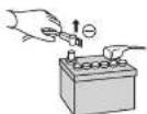

Caution
- If your car is equipped with air bag and/or anti-theft systems specific procedures may be required for connection and disconnection of the battery to install this product.
- Before attempting installation of this electronic component contact your car dealer or manufacturer to determine the required procedure and strictly follow their instructions.
- FAILURE TO FOLLOW THE PROCEDURE MAY RESULT IN THE UNINTENDED DEPLOYMENT OF AIR BAGS OR ACTIVATION OF THE ANTI-THEFT SYSTEM RESULTING IN DAMAGE TO THE VEHICLE AND PERSONAL INJURY.
Installation Hardware (For Installation)
| No. | Item Diagram Qty. | ||
| 1 | Tapping Screw(5 mmφ×20 mm) | 4 | |
| 2 | Plain Washer(5 mmφ) | 4 | |
| 3 | Allen wrench 1 |
Installation Hardware (For Wiring)
| No. | Item Diagram Oly. | ||
| 4 | Speaker input connector | 2※ | |
| 5 | Terminal cover for short-circuit prevention | 2 |
CY-PA4003N: 2 (1 for front speaker, 1 for rear speaker) CY-PA2003N, CY-PAD1003N: 1 (for left/right speaker)
| No. | Item Diagram Qty. | ||
| 8 | Spacer 4 | ||
| 7 | Tapping Screw(5 mmφ×40 mm) | d |
Note:
- For power connection, use the optional power cord specially designed for use with Panasonic car-audio/AV system.
- Use only the supplied screws for installation. If parts are missing please consult with your Panasonic dealer for advice.
Mounting the Unit

Caution
- Never mount the unit in any of the following locations to avoid damage due to overheating:
• Near the heater port. - Places like the dashboard or rear deck, where it may be exposed to direct sunlight.
- Do not mount the unit near the door, where it could be exposed to rain.
- You run the risk of interfering with the mounting or causing damage by drilling into the gas tank, a wiring harness, or other component.
- Keep a safe distance between the unit and other electronic equipment.
- If this unit is operated at a high output continuously, the upper side of the unit will get very hot. Do not touch it nor place anything on top of the unit.
- When a short circuit occurs, such as in the speaker output terminal, etc. the overload protection circuit will operate. This circuit protects the power amplifier from further damage when a short circuit occurs. Operation will temporarily stop. In this case, check the cause of the short-circuit and if the problem is fixed, normal operation will resume.
- Since the power amplifier has a very large output, the unit should be installed in the trunk of your car.
- Do not install this unit under a carpet, otherwise the unit may fail because of immature heat dissipation.
- Use the spacer included when installing the unit so that the fan and air hole on the base side of the unit are not covered.
If the fan and air hole on the base side of the unit are covered, the unit will become extremely hot and may fail.
Before Mounting the Unit
1 Make the temporary connections.
2 Confirm the proper operation of the unit.
Confir rm the proper connection and setting, and no blowout of the fuses.
3 Confi rm after the installation of the unit that the spare tires, the jack, the tools, etc. can be picked up without obstruction.
Install the unit to a metallic portion of the car. Since the power amplifier has a very large output, the unit should be installed in the boot of your car.
text_image
① Tapping Screw (5 mmφ×20 mm) ② Plain Washer (5 mmφ) Drill four holes 3.5 mmφ Metallic panel (thickness: more than 15 mm)
text_image
Tapping Screw (5 mmφ×40 mm) Plain Washer (5 mmφ) Spacer 291 mm 176 mm Drill four holes 3.5 mmφ Metallic panel (thickness: more than 15 mm)Note:
- If you wish to install the unit without using the spacer included, drill holes in the Metallic panel etc so that the fan and air holes on the base side of the unit are not covered.
Base side of CY-PAD1003N:
CY-PA4003N/PA2003N/PAD1003N
Wiring
Caution
- This unit is designed for use in a car having a 12 V negative ground battery system.
- Be sure to insulate any exposed wires to prevent short circuiting with the car chassis. Bundle all cables, and prevent cable terminals from touching any metal parts.
- Note that if your car has a driving computer or a navigation computer, disconnecting the cable from the battery may clear the memory.
- Run the cords avoiding the spots where the temperature can be extremely high.
- Continuous use of a system that exceeds the maximum permissible input levels may damage the speakers.
- Since the power amplifier has a very large output, the unit should be installed in the trunk of your car.
- Do not install this unit under a carpet, otherwise the unit may fail because of immature heat dissipation.
Caution for the power cord (option):
- Follow an expert's instruction for the use of the cord separately sold.
- For the power, make sure to use the battery lead (yellow) separately sold and specially designed for Panasonic car-audio/AV system, and to connect directly to the car battery. Use the cord having the fusa capacity larger than that of this unit. Connect the power cord and other cords corresponding to the power supply after all the connections to the speaker are completed.
-
Keep the battery lead (yellow) away from the speaker cord.
-
Make sure to use the ground load (black) separately sold and specially designed for car audio system, and to connect it to the metal portion of the car chassis.
- Wire the battery lead (yellow), the ground lead (black), the speaker cords, and this unit with as much distance as possible from the antenna, the antenna cords and the car stereo (car radio).
- If the ground wire is common to both left/right and front/rear speaker wirings, this unit cannot be used. Always use the independent lead wire for the speakers to be used. In this case, redo the wiring.
Caution for the speaker cord (option):
- The speaker cords and the power amplifier unit should be kept away from the antenna and antenna extension cord.
- Do not directly ground the speaker cords; do not share the negative leads of multiple speakers.
- When using the RCA cords, keep away from the speaker cords.
Caution for the speaker (option):
■ Use speakers with a suitable maximum input.
- In case of 4-channel/3-channel connection
Use speakers with the impedance of 2-8 g.
■ In case of 2-channel/stereo connection: Use speakers with the impedance of 4–8Ω.
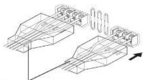
Terminal Cover for Short-circuit Prevention
This terminal cover is for preventing short-circuit between adjacent terminals. Before connecting each lead, pass it through the terminal cover. After connecting the leads to the terminals, cover the speaker output terminals and power terminals with this cover. Make sure that the projections to prevent slipping out are facing down.
natural_image
Pure technical line drawing of electrical connector components without any text or symbols⑤ Terminal cover for short-circuit prevention
natural_image
Pure technical line drawing of electrical connector components without any text or symbols⑤ Terminal cover for short-circuit prevention
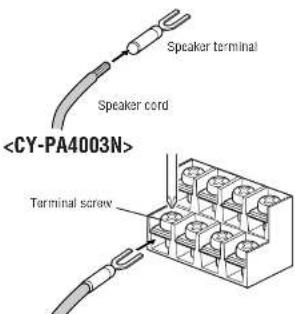
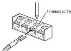
Speaker Output Terminal Screw Connection
text_image
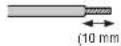
Speaker terminal Speaker cord1 Using a nipper or cutter, expose approximately 10 mm long of the core of the speaker cord and twist its end.
2 Attach the speaker terminal onto the speaker cord.
3 Unscrew the terminal screw.
4 Insert the screw into the terminal of the cord. Securely fasten the screw.
text_image
Terminal screwPower Terminal Screw Connection
Terminal screw Battery terminal
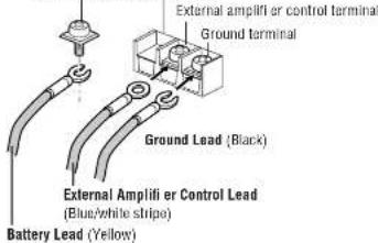
text_image
External amplifier or control terminal Ground terminal Ground Lead (Black) External Amplifier Control Lead (Blue/white stripe) Battery Lead (Yellow)For power connection, use the optional battery lead (yellow) specially designed for car-audio system and connect it directly to the car battery. Use the cord having the fuse capacity larger than that of this unit.
Securely tighten each lead with a terminal screw.
1. Unscrew the terminal screw.
2 Insert the screw into the terminal of the lead. Securely fasten the screw.
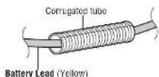
If the battery lead has to be routed through high temperature area, protect it with a corrugated tube (option).
Wiring
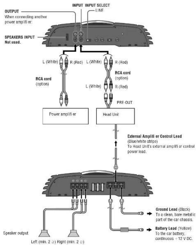
Speaker Connections with RCA cord
Example: 4 channel speaker connection (4CH input)
Note for RCA Input Connection
- Selectively assign each front and rear output to either RCA INPUT A or B, in accordance with the system from which the output is coming.
- In case of a single line coming from the RCA output of Head Unit, connect the line to RCA INPUT A.
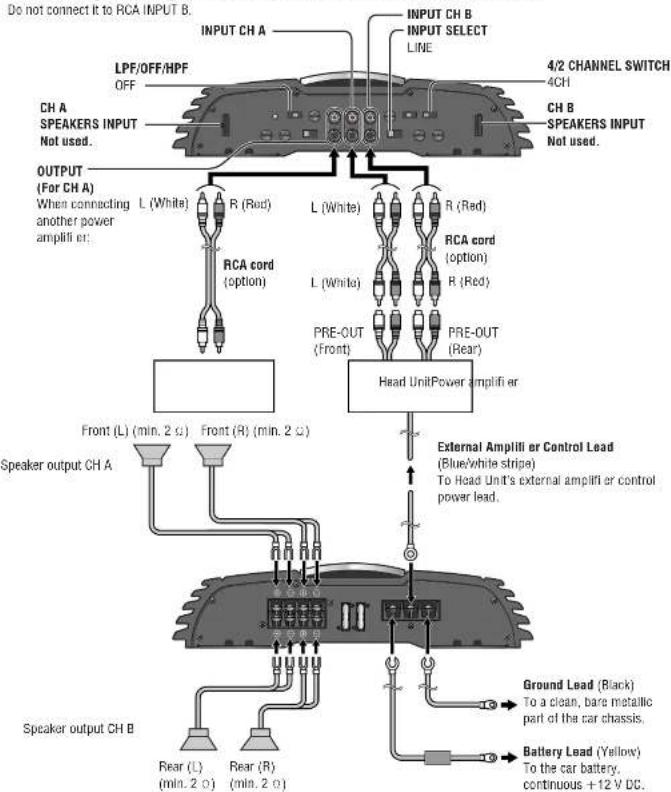
flowchart
graph TD
    A["CH A SPEAKERS INPUT Not used."] --> B["LPF/OFF/NPF OFF"]
    B --> C["INPUT CH A"]
    C --> D["INPUT CH B INPUT SELECT LINE"]
    D --> E["4/2 CHANNEL SWITCH 4CH"]
    E --> F["CH B SPEAKERS INPUT Not used."]
    G["OUTPUT (For CH A) When connecting another power amplifier"] --> H["RCA cord (option)"]
    H --> I["RCA cord (option)"]
    I --> J["RCA cord (option)"]
    J --> K["RCA cord (option)"]
    K --> L["RCA cord (option)"]
    L --> M["RCA cord (option)"]
    M --> N["RCA cord (option)"]
    N --> O["RCA cord (option)"]
    O --> P["RCA cord (option)"]
    P --> Q["RCA cord (option)"]
    Q --> R["RCA cord (option)"]
    R --> S["RCA cord (option)"]
    S --> T["RCA cord (option)"]
    T --> U["RCA cord (option)"]
    U --> V["RCA cord (option)"]
    V --> W["RCA cord (option)"]
    W --> X["RCA cord (option)"]
    X --> Y["RCA cord (option)"]
    Y --> Z["RCA cord (option)"]
    Z --> AA["RCA cord (option)"]
    AA --> AB["RCA cord (option)"]
    AB --> AC["RCA cord (option)"]
    AC --> AD["RCA cord (option)"]
    AD --> AE["RCA cord (option)"]
    AE --> AF["RCA cord (option)"]
    AF --> AG["RCA cord (option)"]
    AG --> AH["RCA cord (option)"]
    AH --> AI["RCA cord (option)"]
    AI --> AJ["RCA cord (option)"]
    AJ --> AK["RCA cord (option)"]
    AK --> AL["RCA cord (option)"]
    AL --> AM["RCA cord (option)"]
    AM --> AN["RCA cord (option)"]
    AN --> AO["RCA cord (option)"]
    AO --> AP["RCA cord (option)"]
    AP --> AQ["RCA cord (option)"]
    AQ --> AR["RCA cord (option)"]
    AR --> AS["RCA cord (option)"]
    AS --> AT["RCA cord (option)"]
    AT --> AU["RCA cord (option)"]
    AU --> AV["RCA cord (option)"]
    AV --> AW["RCA cord (option)"]
    AW --> AX["RCA cord (option)"]
    AX --> AY["RCA cord (option)"]
    AY --> AZ["RCA cord (option)"]
    AZ --> BA["RCA cord (option)"]
    BA --> BB["RCA cord (option)"]
    BB --> BC["RCA cord (option)"]
    BC --> BD["RCA cord (option)"]
    BD --> BE["RCA cord (option)"]
    BE --> BF["RCA cord (option)"]
    BF --> BG["RCA cord (option)"]
    BG --> BH["RCA cord (option)"]
    BH --> BI["RCA cord (option)"]
    BI --> BJ["RCA cord (option)"]
    BJ --> BK["RCA cord (option)"]
    BK --> BL["RCA cord (option)"]
    BL --> BM["RCA cord (option)"]
    BM --> BN["RCA cord (option)"]
    BN --> BO["RCA cord (option)"]
    BO --> BP["RCA cord (option)"]
    BP --> BQ["RCA cord (option)"]
    BQ --> BR["RCA cord (option)"]
    BR --> BS["RCA cord (option)"]
    BS --> BT["RCA cord (option)"]
    BT --> BU["RCA cord (option)"]
    BU --> BV["RCA cord (option)"]
    BV --> BW["RCA cord (option)"]
    BW --> BX["RCA cord (option)"]
    BX --> BY["RCA cord (option)"]
    BY --> BZ["RCA cord (option)"]
    BZ --> CA["Speaker output CH A"]
    CA --> CB["Speaker output CH B"]
    CB --> CC["Ground Lead (Black) To a clean, bare metallic part of the car chassis."]
    CB --> DD["Battery Lead (Yellow) To the car battery, continuous +12 V DC."]
CY-PA4003N/PA2003N/PAD1003N
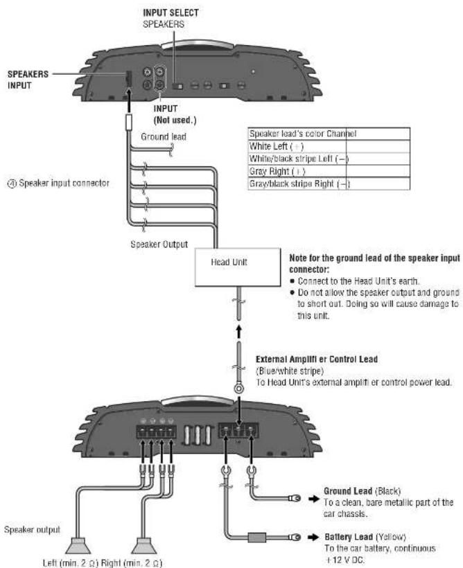
Speaker Connections with SPEAKERS INPUT Connectors
Example: 4 channel speaker connection (4CH input)
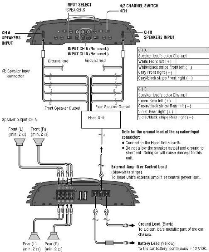
text_image
INPUT SELECT SPEAKERS 4/2 CHANNEL SWITCH 4CH CH A SPEAKERS INPUT CH B SPEAKERS INPUT INPUT CH A (Not used.) INPUT CH B (Not used.) Ground lead Ground lead Speaker input connector Front Speaker Output Rear Speaker Output Head Unit Speaker output CH A Front (L) (min, 2 Ω) Front (R) (min, 2 Ω) External Amplifi er Control Lead (Blue/white stripe) To Head Unit's external amplifi er control power lead. Ground Lead (Black) To a clean, bare metallic part of the car chassis. Rear (L) (min, 2 Ω) Rear (R) (min, 2 Ω) Battery Lead (Yellow) To the car battery, continuous +12 V DC. Note for the ground lead of the speaker input connector: Connect to the Head Unit's earth. Do not allow the speaker output and ground to short out. Doing so will cause damage to this unit.Speaker output CH B
CY-PA4003N/PA2003N/PAD1003N
Wiring
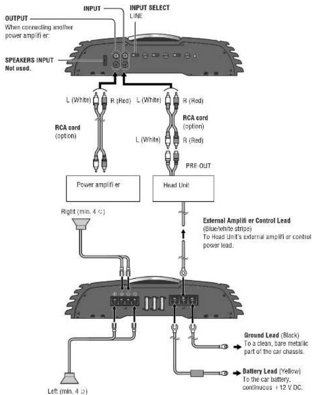
Speaker Connections with RCA cord
Example: 2 channel speaker connection
flowchart
graph TD
    A["Speaker output"] --> B["Ground Lead (Black)"]
    A --> C["Battery Lead (Yellow)"]
    B --> D["To a clean, bare metallic part of the car chassis."]
    C --> E["To the car battery, continuous +12 V DC."]
    F["RCA cord (option)"] --> G["L (White)"]
    F --> H["R (Red)"]
    I["Head Unit"] --> J["L (White)"]
    I --> K["R (Red)"]
    L["Speaker INPUT"] --> M["L (White)"]
    N["INPUT SELECT LINE"] --> O["L (White)"]
    P["OUTPUT"] --> Q["L (White)"]
    R["Time constant: 0.5s"] --> S["Current: Left (min. 2 Ω) Right (min. 2 Ω)"]
    T["External Amplifi or Control Lead (Blue/white stripe)"] --> U["To Head Unit's external amplifier or control power lead."]
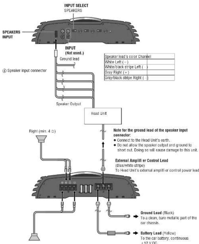
Speaker Connections with SPEAKERS INPUT Connectors
Example: 2 channel speaker connection
flowchart
graph TD
    A["Speaker input connector"] --> B["Ground lead"]
    B --> C["Speaker Output"]
    C --> D["Head Unit"]
    D --> E["External Amplifier Control Lead (Blue/white stripe)"]
    E --> F["Speaker output"]
    F --> G["Ground Lead (Black)"]
    G --> H["Battery Lead (Yellow)"]
    H --> I["To the car battery, continuous +12 V DC."]
    style A fill:#f9f,stroke:#333
    style D fill:#ccf,stroke:#333
    style E fill:#cfc,stroke:#333
    style F fill:#fcc,stroke:#333
    style G fill:#ffc,stroke:#333
    style H fill:#fcc,stroke:#333
Wiring
Speaker Connections with RCA cord
Example: 2 channel Input System
flowchart
graph TD
    A["Speaker Input Not used"] --> B["Input Select Line"]
    B --> C["RCA cord (option)"]
    C --> D["Power amplifier"]
    D --> E["Head Unit"]
    E --> F["External Amplifier Control Lead (Blue:white stripe)"]
    F --> G["Ground Lead (Black)"]
    F --> H["Battery Lead (Yellow)"]
    G --> I["To a clean, bare metallic part of the car chassis."]
    H --> J["To the car battery, continuous +12 V DC."]
Speaker Connections with SPEAKERS INPUT Connectors
Example: 2 channel Input System
flowchart
graph TD
    A["INPUT SELECT SPEAKERS"] --> B["Speaker Input connector"]
    B --> C["Ground Lead"]
    C --> D["Speaker Output"]
    D --> E["Head Unit"]
    E --> F["External Amplifier Control Lead (Blue/white stripe)"]
    F --> G["Ground Lead (Black)"]
    F --> H["Battery Lead (Yellow)"]
    G --> I["To a clean, bare metallic part of the car chassis."]
    H --> J["To the car battery, continuous +12 V DC."]
Troubleshooting
If You Suspect Something Wrong
Check and take steps as described below.
If the described suggestions do not solve the problem, it is recommended to take the unit to your nearest authorized Panasonic Service Centre. The product should be serviced only by qualified personnel. Please refer checking and repair to professionals. Panasonic shall not be liable for any accidents arising out of neglect of checking the unit or your own repair after your checking.
Never take measures especially those other than indicated by italic letters in “Possible solution” described below because those are too dangerous for users to handle themselves.
| Problem Possible cause | Possible solution → |
| No sound available. The power cord (battery, power and ground) is connected in the wrong way.→ Check the wiring. | |
| Problem Possible cause | Possible solution → |
| No sound available. (continued) | There is an electromagnetic-wave generator such as a cellular phone near the unit or its electrical lines.→ Keep the electromagnetic-wave generator such as a cellular phone away from the unit and the wiring of the unit. If noise cannot be eliminated due to the wiring harness of the car, consult your dealer. |
| Fuse blows out.→ Eliminate the cause of fuse blowout and replace the fuse with new one. Consult your dealer. | |
| Bad sound quality (Distorted sound) Noise | The bass is too much enhanced.→ Set the bass boost appropriately. |
| Sound comes out from only either the Front 2CH or the Rear 2CH. | The 2CH/4CH setting of the speaker input is incorrect.→ Set it correctly. |
| Only the bass is available. | The Crossover Filter Switch (LPF/OFF/HPF) is turned off.→ Set it on LPF or HPF according to the speaker connection.The Crossover Filter Switch (LPF/OFF) is turned off.→ Set it on LPF according to the speaker connection. |
| Only the treble is available. | The setting of Crossover Frequency Control is Incorrect.→ Check the Crossover Frequency Control setting. |
| The Protect lamp lights red. | The speaker cord is short-circuited.→ Check the speaker cord, and replace the fuse. |
| The speaker received damage because of too small input capacity.→ Obtain the right speaker allowed to connect this unit, and replace the fuse. (page 32) | |
| The speaker cord is not properly connected.→ Properly reconnect so that the polarity matches between the speaker cord and the terminal. | |
| Fuse blows out.→ Eliminate the cause of fuse blowout and replace the fuse with new one. Consult your dealer. |
Troubleshooting (continued)
Product Servicing
If the suggestions in the charts do not solve the problem, we recommend that you take it to your nearest authorized Panasonic Service Centre. The product should be serviced only by a qualified technician.
Replacing the Fuse
Warning
Use fuses of the same specified rating.
CY-PA4003N: 35 A×2
CY-PA2003N: 25 A×3
CY-PAD1003N: 25 A×3
When replacing one fuse which has blown, replace other fuses at the same time.
In some cases, fuses may deteriorate without failing. Using different substitutes or fuses with higher ratings, or connecting the unit directly without a fuse, could cause fl re or damage to the unit.
If the replacement fuse fails, contact your nearest Panasonic Service Centre for service.
Maintenance
Caution on Cleaning

Your product is designed and manufactured to require minimum maintenance. Use a dry soft cloth for routine exterior cleaning. Never use benzine, thinner or other solvents.
Specifications
Power Supply: DC 12 V (11 V–16 V), test
voltage 14.4 V,
Negative
Current Consumption: 32 A (at 64 W×4)
Speaker Impedance: 4 Ω
Power Output ("EIA" Power):
2-CH: 190 W×2 (20 Hz-20 000 Hz, 1 %, 4 Ω)
3-CH: 64 W×2+190 W (20 Hz-20 000 Hz, 1 %, 4 Ω)
4-CH: 64 W×4 (20 Hz-20 000 Hz, 1 %, 4 O)
Maximum Power Output:
2-GH: 220 W×2 (20 Hz-20 000 Hz, 10 %)
3-CH: 85 W×2+220 W (20 Hz-20 000 Hz, 10 %)
4-GH: 85 W×4 (20 Hz-20 000 Hz, 10 %)
Total Harmonic Distortion: 0.08 % (1 000 Hz, at 10 W)
Low Pass Filter: 50 Hz–250 Hz
High Pass Filter: 50 Hz—250 Hz
Bass Boost : 0 dB—15 dB (Middle
Frequency: 45 Hz)
Signal to Noise Ratio: 90 dB (IHF, A)
Frequency Response: 20 Hz–20 kHz
Input Sensitivity: 0.2 V–6 V
Input Impedance: More than 46 kΩ
Dimensions (W×H×D): 280×62×333 mm
Weight:
4.4 g
Note:
- Specifi cations and design are subject to modifi cation without notice due to improvements.
- Some fl gures and illustrations on this manual may be different from your product.
Power Supply: DC 12 V (11 V–16 V), test
voltage 14.4 V,
Negative
Ground
Current Consumption: 44 A (at 200 W×2)
Speaker Impedance: 4 Ω
Power Output ("EIA" Power)
1-CH (Monaural): 480 W×1 (20 Hz–20 000 Hz, 1 %, 4 Ω)
2-CH (Stereo): 200 W×2 (20 Hz–20 000 Hz, 1 %, 4 Ω)
Maximum Power Output:
1-CH (Monaural): 550 W×1 (20 Hz–20 000 Hz, 10 %)
2-CH (Stereo): 260 W×2 (20 Hz–20 000 Hz, 10 %)
Total Harmonic Distortion: 0.08 % (1 000 Hz, at 10 W)
Low Pass Filter: 50 Hz–250 Hz
High Pass Filter: 50 Hz–250 Hz
Bass Boost: 0 dB–15 dB (Middle
Frequency: 45 Hz)
Signal to Noise Ratio: 90 dB (IHF, A)
Frequency Response: 20 Hz—20 kHz
Input Sensitivity: 0.2 V–6 V
Input Impedance: More than 43 kg
Dimensions (W×H×D): 280×62×333 mm
Weight:
4.5 g
Note:
- Specific cations and design are subject to modification without notice due to improvements.
- Some 11 gures and illustrations on this manual may be different from your product.
Power Supply: DC 12 V (11 V–16 V), test
voltage 14.4 V,
Ground
Negative
Current Consumption: 29 A (at 350 W×1)
Speaker Impedance: 4 D
Power Output ("EIA" Power)
1-CH (Monaural): 350 W×1 (10 Hz–8 000 Hz, 1 %, 4 Ω)
Maximum Power Output:
1-CH (Monaural): 600 W×1 (10 Hz–8 000 Hz, 10 %)
Total Harmonic Distortion: 0.2 % (1 000 Hz, at 10 W)
Low Pass Filter: 50 Hz–250 Hz
Bass Boost:
0 dB-15 dB (Middle
Frequency: 45 Hz)
Subsonic Filter: 20 Hz, -3 dB, 12 dB/oct
Signal to Noise Ratio: 90 dB (IHF, A)
Frequency Response: 10 Hz–8 kHz
Input Sensitivity: 0.2 V—6 V
Input Impedance: More than 22 kΩ
Dimensions (W×H×D): 280×62×303 mm
Weight:
4.0 g
Note:
- Specifications and design are subject to modification without notice due to improvements.
- Some figures and illustrations on this manual may be different from your product.
Sales and Support Information
For UK and Ireland customers only.
Customer Care Centre
- For customers within the UK: 08705 357357
● For customers within the Republic of Ireland: 01 289 8333 - Visit our website for product information
• E-mail: customer.care@panasonic.co.uk
Direct Sales at Panasonic UK
- Order accessories and consumable items for your product with ease and confidence by phoning our Customer Care Centre Monday - Thursday 9:00am - 5:30pm. Friday 9:30am - 5:30pm. (Excluding public holidays).
- Or go on line through our Internet Accessory ordering application at www.panasonic.co.uk.
● Most major credit and debit cards accepted. - All enquiries transactions and distribution facilities are provided directly by Panasonic UK Ltd.
- It couldn't be simpler!
- Also available through our Internet is direct shopping for a wide range of finished products, so take a browse on our website for further details.