PR600 - Sewing machine BROTHER - Free user manual and instructions
Find the device manual for free PR600 BROTHER in PDF.
User questions about PR600 BROTHER
0 question about this device. Answer the ones you know or ask your own.
Ask a new question about this device
Download the instructions for your Sewing machine in PDF format for free! Find your manual PR600 - BROTHER and take your electronic device back in hand. On this page are published all the documents necessary for the use of your device. PR600 by BROTHER.
USER MANUAL PR600 BROTHER
Cylinder Frame User's Guide
INCLUDED ACCESSORIES 2
IMPORTANT NOTE 3
EMBROIDERY SAMPLES USING THE CYLINDER FRAME 3
DIAMETER AND DEPTH OF BAGS AND CYLINDRICAL ITEMS THAT CAN BE EMBROIDERED 4
Knit ribbing on cuffs (such as on golf club covers) 4
Cylindrical items (such as pant legs or shirts) 4
FABRICS 5
PREPARING TO USE THE CYLINDER FRAME 5
Installing the cylinder frame driver ....5
Adjusting the cylinder frame driver (only when used for the first time) 7
Installing the needle plate spacer 8
Preparing the cylinder frame mounting jig 8
INSTALLING THE CYLINDER FRAME 9
Hooping the fabric in the cylinder frame 9
Attaching the cylinder frame to the machine ....11
Removing the cylinder frame 12
INSTALLING THE EMBROIDERY FRAME HOLDER 12
ADDITIONAL DIGITIZING INFORMATION 14
Included accessories
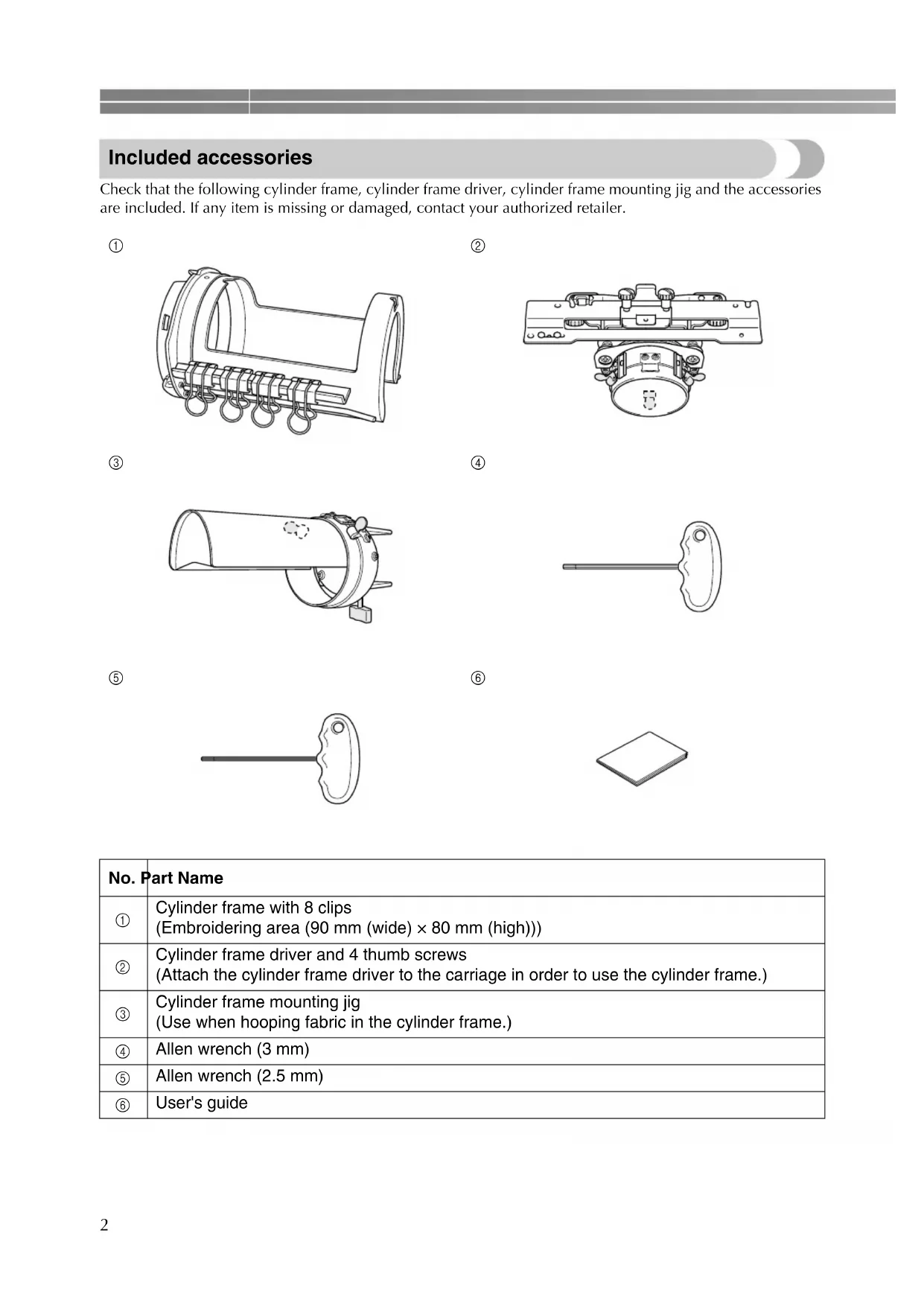
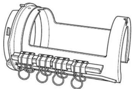
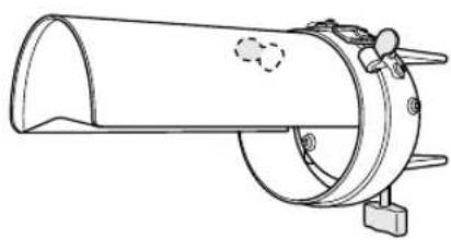
Check that the following cylinder frame, cylinder frame driver, cylinder frame mounting jig and the accessories are included. If any item is missing or damaged, contact your authorized retailer.
①
natural_image
Technical line drawing of a mechanical component with coiled spring and housing (no text or symbols)②

natural_image
Technical line drawing of a mechanical assembly with no visible text or symbols③
natural_image
Technical line drawing of a cylindrical mechanical component with mounting base (no text or symbols)④
natural_image
Simple line drawing of a key with a handle and pointed tip (no text or symbols)⑤

natural_image
Simple line drawing of a key-like object with a handle and pointed tip (no text or symbols)⑥
| No. | Part Name |
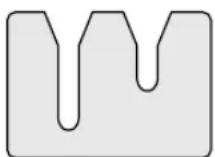
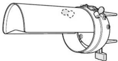
| 1 | Cylinder frame with 8 clips(Embroidering area (90 mm (wide) × 80 mm (high))) |
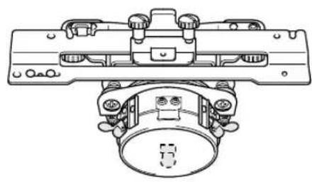
| 2 | Cylinder frame driver and 4 thumb screws(Attach the cylinder frame driver to the carriage in order to use the cylinder frame.) |
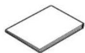
| 3 | Cylinder frame mounting jig(Use when hooping fabric in the cylinder frame.) |
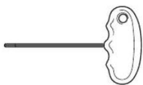
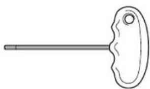
| 4 | Allen wrench (3 mm) |
| 5 | Allen wrench (2.5 mm) |
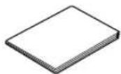
| 6 | User's guide |
Important note
- Do not place floppy disks or magnetic cards near the cylinder frame driver. The cylinder frame driver is equipped with extremely strong magnets, which may affect magnetic media.
●Before installing the cylinder frame driver, verify the version of your machine by checking the shape of the notch in the connecting plate installed on the carriage.
Split in two (before upgrading)

Split in three (after upgrading)
- If the notch is not split in three, the embroidery machine is the older version. Purchase the upgrade kit (sold separately) and upgrade the embroidery machine. For details, contact your authorized retailer.
- Before installing the cylinder frame, be sure to adjust the cylinder frame driver. If the same machine is being used, this adjustment is only required the first time that it is used. For details, refer to "Adjusting the cylinder frame driver (only when used for the first time)" on page 7.
●After the cylinder frame driver has been adjusted, it must be adjusted again if a different machine is being used. Adjust the driver for each machine that is used. For details, contact your authorized retailer.

Memo
- When the cylinder frame is attached, the following embroidery frame indicator (indicator showing the embroidery frames that can be used) appears.

By using the cylinder frame, patterns can be embroidered onto bags and cylindrical items. The procedures for using the cylinder frame are described below.
Embroidery samples using the cylinder frame
text_image
A B C A B C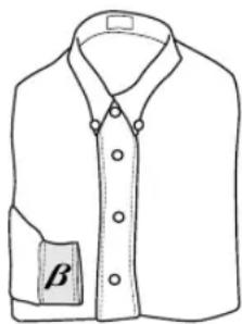
natural_image
Line drawing of a collared shirt with a button labeled 'β' on the side (no other text or symbols)
text_image
350mm ABC ①①Only this area can be embroidered.

Memo
●There are various conditions on the size and fabric in order to embroider. For details on these conditions, refer to page 4 through 5.
- When embroidering golf club covers, check that the fabric is elastic and is a size that fits in the cylinder frame. In addition, only one-point embroidery patterns can be sewn in the area indicated in the illustration.
Diameter and depth of bags and cylindrical items that can be embroidered
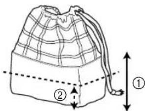
The items embroidered using the cylinder frame must have the diameter and depth shown below. The diameter refers to the width of the bag or cylindrical item, and the depth refers to the height of the bag or cylindrical item.
text_image
Diagram showing fabric folding process: one bag with crisscross pattern being folded, second bag with grid pattern and labeled parts ① and ②① 155 mm (6 1/8 inches)
②Must have a width of 155 mm (6 1/8 inches) or more (when folded).
- Depth
text_image
Diagram of a bag with labeled parts and measurement arrows, showing internal structure and spacing.① Must have a height of 70 mm (2 3/4 inches) or more from the bottom.
②70 mm (2 3/4 inches)

Memo
●The embroidering position on bags differs depending on the width of the bag.
- With a width of 155 mm (6 1/8 inches) or less: The embroidery can be sewn at a height of 70 mm (2 3/4 inches) or more from the bottom.
- With a width of 155 mm (6 1/8 inches) or more: The height of the embroidery position depends on the width of the bag.
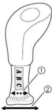
■Knit ribbing on cuffs (such as on golf club covers)
text_image
① ② A B C① 155 mm (6 1/8 inches)
②Must have a width of 155 mm (6 1/8 inches) or more (when folded).
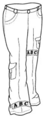
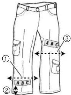
■Cylindrical items (such as pant legs or shirts)
text_image
① ② A B C ③① 155 mm (6 1/8 inches) or more
②22mm (7/8 inch) or more
③175 mm (6 7/8 inches) or more
- Diameter: Must have a width of 155 mm (6 1/8 inches) or more (when folded).
- Depth: Must be 22mm (7/8 inch) or more from the hem.

Memo
- When embroidering at a position more than 130 mm (5 1/8 inches) from the pant hem, such as at the knee, the width must be 175 mm (6 7/8 inches) or more when folded.
Fabrics
For best results, it is recommended to use the following types of fabrics.
- 100 % cotton
• 35% cotton/65% polyester - 80% wool/20% nylon
• 15% wool/85% acrylic
Fabrics that are difficult to hoop, wrinkle easily or shrink are not recommended to be used with the cylinder frame. Fabrics such as:
- Polyester foam
- Stretch fabrics
- Melton wool
- 100% nylon
- Suede

Note
●Patterns that misalign easily should not be embroidered using this cylinder frame.
●Only use one-point embroidery patterns or letters on ribbed knit fabrics.
Preparing to use the cylinder frame
■Installing the cylinder frame driver
Remove the embroidery frame holder from the carriage, and then install the cylinder frame driver.

Memo
●Before removing the embroidery frame holder, remove the embroidery frame. For details on the removal procedure, refer to "Removing the embroidery frame" in the Operation Manual.
1
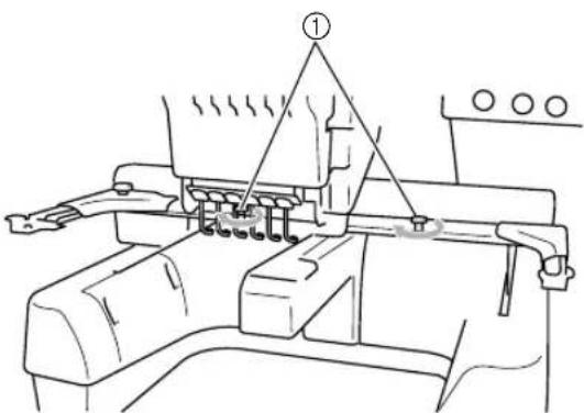
Loosen and remove the two thumb screws, and then remove the embroidery frame holder.
text_image
Technical diagram of a mechanical assembly with numbered components and directional arrows indicating motion or movement.① Thumb screws
②Embroidery frame holder
- The removed thumb screws remain attached to the embroidery frame holder.
text_image
Technical diagram of a mechanical bracket with numbered parts and an inset showing a detail view of a component with downward arrows.① Leave the two thumb screws attached so they are not lost.
②Embroidery frame holder
2
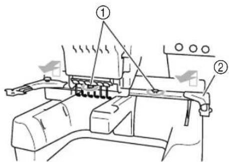
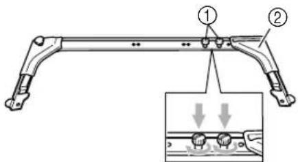
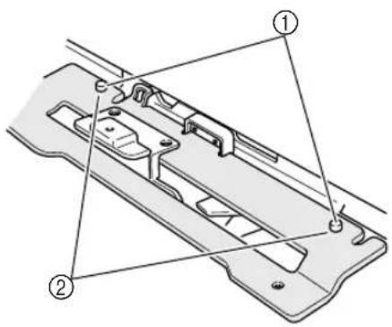
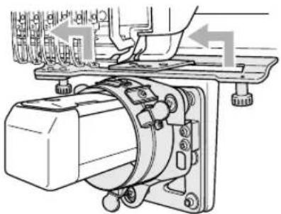
Remove the two upper thumb screws of the cylinder frame driver, and then loosen the two lower thumb screws.
text_image
Technical diagram of a mechanical assembly with labeled parts and directional arrows indicating motion or assembly.①Upper thumb screws (smaller)
②Lower thumb screws (larger)

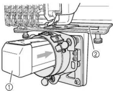
Pass the machine bed through the ring of the cylinder frame driver.
text_image
Technical diagram of an electrical motor assembly with labeled parts ① and ②① Machine bed
②Gap in the mounting plate

Note
●Be careful that the cylinder frame driver does not hit any nearby parts, such as the presser foot or the gap in the mounting plate.

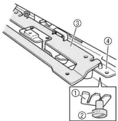
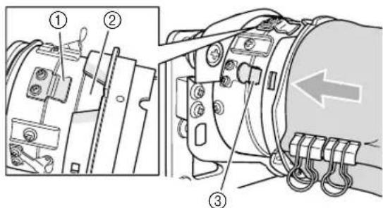
Insert the two thumb screws at the bottom of the cylinder frame driver into the notches in the carriage, and then place the mounting plate of the cylinder frame driver on top of the X carriage.
text_image
Technical diagram of a mechanical component with numbered parts and an inset view showing two labeled parts.① Notch in the carriage
②Thumb screw of the cylinder frame driver
③Mounting plate of the cylinder frame driver
④X carriage

Insert the pins on the X carriage into the holes in the mounting plate of the cylinder frame driver.
text_image
Technical diagram of a mechanical component with numbered parts labeled ① and ②① Pins on the X carriage
②Holes in the mounting plate of the cylinder frame driver

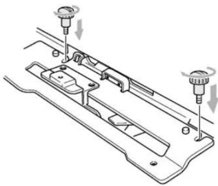
Tighten the two thumb screws removed in step 2.
natural_image
Technical diagram of a mechanical assembly with two screw fasteners and a central component (no text or labels)
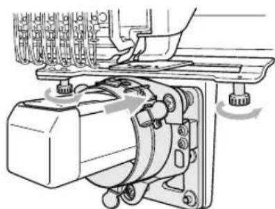
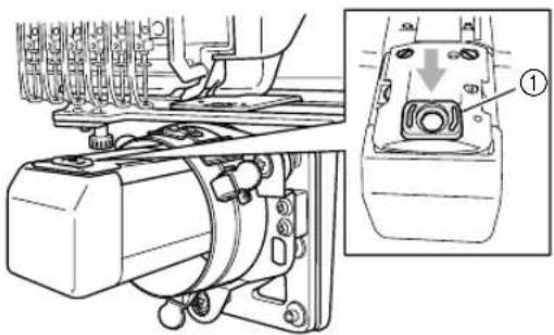
While pushing in the cylinder frame driver so that it is fully inserted, tighten the two lower thumb screws to secure the cylinder frame driver.
natural_image
Mechanical assembly diagram showing a motor with rotating components and a hand operating it (no text or symbols present)This completes the installation of the cylinder frame driver.

Memo
● Using the disc-shaped screwdriver included with the embroidery machine, firmly tighten the thumb screws.
■Adjusting the cylinder frame driver (only when used for the first time)
text_image
Technical diagram of a mechanical assembly with numbered components labeled ①, ②, and ③.① L-shaped mounting bracket
②Ring
③Fitting in ring

Note
- Adjust the cylinder frame driver only when it is being used for the first time. If the same machine will be used, this adjustment will not be required with later uses. However, if the cylinder frame driver is used with a different machine and the settings are changed, the adjustment must be performed again.

Set the main power switch to "I" to turn on the machine. After the carriage moves to its initial position, turn off the machine.

Memo
●Be sure to adjust the cylinder frame driver at its initial position. For details on the initial position, refer to the Operation Manual.

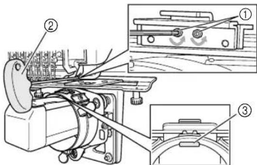
Using the enclosed Allen wrench (2.5 mm), turn the two hexagonal screws one turn in the direction of the arrow to loosen them. When the hexagonal screws are loosened, the fitting in the ring is lowered.
text_image
Technical diagram of a mechanical assembly with numbered components and close-up views of parts labeled ①, ②, and ③.① Hexagonal screws
②Enclosed Allen wrench (2.5 mm)
③Fitting in ring

Note
●Do not remove the hexagonal screws.

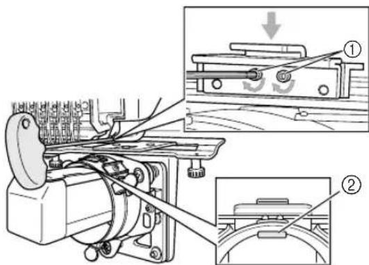
While lightly pressing down with your finger on the L-shaped mounting bracket so that it touches the top surface of the machine bed, use the Allen wrench (2.5 mm) to firmly tighten the two hexagonal screws.
text_image
Technical diagram of a mechanical device with labeled parts and an inset showing a mechanical assembly with motion indicators.① L-shaped mounting bracket
②Fitting in ring

Memo
● Firmly tighten the hexagonal screws so that the fitting in the ring touches the surface of the machine bed.

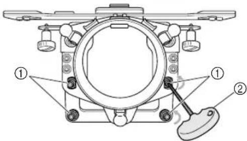
Using the enclosed Allen wrench (3 mm), turn the four hexagonal screws outside the ring one turn in the direction of the arrow to loosen them.
text_image
Technical diagram of a mechanical assembly with labeled parts ① and ②, showing components like gears and a lever.①Hexagonal screws
②Enclosed Allen wrench (3 mm)
When the hexagonal screws are loosened, the ring can be lowered.

Memo
●Do not remove the hexagonal screws.

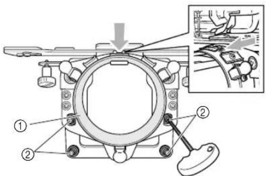
While lightly pressing down on the ring, so that the spacing between the ring and the bed are equal on the left and right sides, use the Allen screwdriver (3mm) to evenly tighten the opposite hexagonal screws on the outside of the ring, and then tighten the other two hexagonal screws. Firmly tighten all 4 screws.
text_image
Technical diagram of a mechanical assembly with numbered components and an inset showing a close-up of a component detail.① Ring
②Hexagonal screws

Note
- If the screws are not firmly tightened, the cylinder frame driver may be damaged.
●To avoid damage to the machine or fabric, make sure that no excess material is allowed into the gap.
■Installing the needle plate spacer
Attach the needle plate spacer (included with the machine) to the needle plate.
natural_image
Technical line drawing of a mechanical assembly with an inset close-up showing a component labeled (1), no readable text or symbols present.① Needle plate spacer
■Preparing the cylinder frame mounting jig
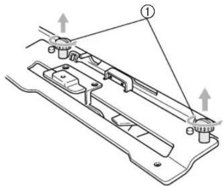
Attach the cylinder frame mounting jig to a level, stable surface, such as a desk.

Loosen the mounting jig thumb screw to increase the space in the mounting bracket so that it is wider than the thickness of the mounting surface.
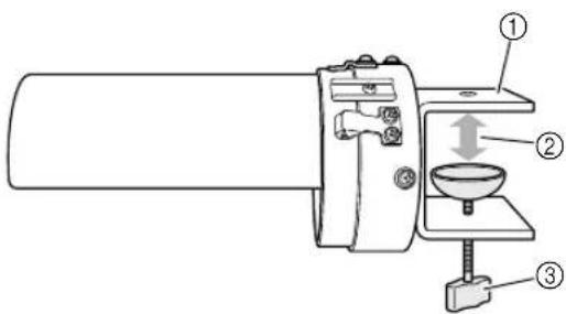
text_image
Technical diagram of a mechanical device with numbered components and directional arrows indicating motion or movement.① Mounting bracket
②Open to desired width.
③Thumb screw
- The mounting bracket can be attached to a surface 9 to 38mm (11/32 to 1 1/2 inches) thick.

Securely clamp the mounting bracket onto the mounting surface, and then tighten the thumb screw.
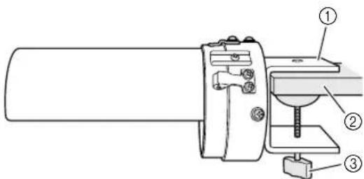
text_image
Technical diagram of a sewing machine with numbered components for identification① Mounting bracket
②Mounting surface (worktable, desk, etc.)
③Tighten the thumb screw.

Check that the mounting jig is secure.
If the mounting jig is not firmly secured to the mounting surface, re-attach the mounting jig and tighten the thumb screw.

Note
●Make sure that the mounting bracket is securely clamped onto the mounting surface and that the thumb screw is firmly tightened.
●Do not attach the mounting jig to an unstable surface (flexible, bent or warped).
●Be careful that the cylinder frame mounting jig does not fall when it is removed.
Installing the cylinder frame
Hoop the fabric in the cylinder frame, and then attach the cylinder frame to the cylinder frame driver.
■Hooping the fabric in the cylinder frame

Attach the cylinder frame to the cylinder frame mounting jig.
Align the notch in the cylinder frame with the guiding plate on the cylinder frame mounting jig. Hold the frame horizontal with the mounting jig and push the frame in until it snaps into place.
text_image
Technical diagram of a mechanical device with numbered components and an inset view showing internal parts with labeled parts ① and ②.① Guiding plate on cylinder frame mounting jig
②Notch in cylinder frame
③Mounting jig holder
The cylinder frame is secured with the two holders.

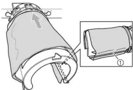
Position the stabilizer into the stabilizer holder on the cylinder frame.
natural_image
Technical illustration of a mechanical component with an inset showing a close-up view of a cylindrical part (no text or symbols present)① Stabilizer holder
- There is a stabilizer holder on the left side and on the right side. On one side, insert the end of the stabilizer between the stabilizer holder and the cylinder frame. Wrap the top of the cylinder frame and extend the stabilizer to the stabilizer holder on the opposite side. Straighten and firmly position the stabilizer.
- Secure the stabilizer so that it does not extend past the dotted line in the direction of the arrow shown in the illustration above.
- Depending on the type of fabric used, it may be necessary to use two to three layers of stabilizer for successful embroidering.
- It is recommended to use stabilizer 130 mm x 250 mm (5" x 7") in size. If the stabilizer is too large, it may be difficult to hoop the fabric.

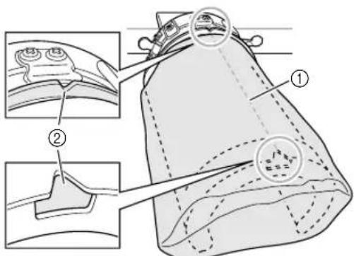
Align the center of the design placement with the notch in the cylinder frame mounting jig.
text_image
Medical diagram showing anatomical structures of a device with labeled parts, including two views and numbered annotations.① Center of design placement
②Notch in cylinder frame mounting jig

Memo
●Before positioning the fabric and stabilizer in the frame, mark the center of the design placement with a chalk pencil.

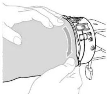
Pull the ends of the fabric out from the center to remove any slack. Be careful not to shift the center of the design placement.
natural_image
Illustration of hands holding a device with a tool inserted (no text or symbols visible)
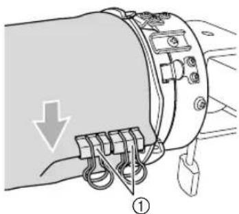
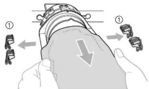
Use the clips to secure the fabric and stabilizer.
natural_image
Diagram of a mechanical device with labeled parts and an arrow indicating direction (no text or symbols present)① Clips
- Repeat steps ④ and ⑤ on the other side to remove any slack and secure the fabric with the clips.

Note
- When securing the fabric with the clips, the handles (rings) should be pointing downward.

Remove the cylinder frame from the cylinder frame mounting jig.
Press on the two holders on the mounting jig with both thumbs, and then pull the cylinder frame straight off in the direction of the arrow shown in the illustration.
text_image
Technical diagram showing mechanical assembly steps with numbered component and directional arrows indicating movement① Mounting jig holders

Note
- When removing the cylinder frame from the mounting jig, carefully pull the frame off so that the fabric and stabilizer are not misaligned.
■Attaching the cylinder frame to the machine

Memo
●Before attaching the cylinder frame to the embroidery machine, attach the cylinder frame driver to the machine carriage. For details on the installation procedure, refer to "Installing the cylinder frame driver" on page 5.

Attach the cylinder frame to the cylinder frame driver.

Note
●When attaching the cylinder frame to the machine,
- Be careful that the cylinder frame or fabric does not hit the presser foot, gap in the mounting plate, or other machine parts.
- Check that the fabric does not cup inside the cavity of the cylinder frame.
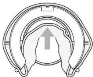
natural_image
Diagram of a mechanical component with concentric rings and a central upward arrow (no text or symbols)
Now embroider your pattern.
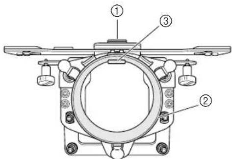
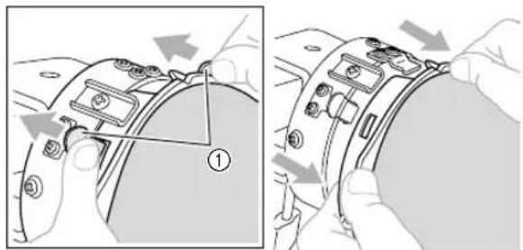
With the embroidering surface up, align the ring of the cylinder frame driver with the ring of the cylinder frame. Align the notch in the frame with the guiding plate on the driver, and then push the frame until it snaps into place.
Three driver holders secure the cylinder frame in place.
text_image
Technical diagram showing mechanical assembly with numbered components and directional arrow indicating motion① Guiding plate on the cylinder frame driver
②Notch in cylinder frame
③Driver holder

Note
●To avoid damage to the machine or fabric, secure any excess fabric that is close to any moving parts, in small areas of the cylinder frame driver, or within the embroidery area.
- When sewing large garments, support the weight of the garment so as not to distort the embroidery pattern.
■Removing the cylinder frame
After finishing sewing, remove the cylinder frame, then the fabric.
1 Remove the cylinder frame from the cylinder frame driver.
Press down the two holders at the base of the cylinder frame with both thumbs, and then pull the cylinder frame off of the machine, as shown in the illustration.
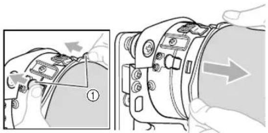
text_image
Technical diagram showing a device's internal components with numbered annotations and directional arrows indicating assembly or repair.① Driver holders

Note
- When removing the cylinder frame, be careful not to hit the presser foot or any nearby machine parts.
2 Remove the clips, and then pull the fabric toward you to release stabilizer from the stabilizer holder.
text_image
Diagram illustrating a hand holding a device with two labeled parts (① and ②) showing different mechanical or electrical components.① Clips
Installing the embroidery frame holder
After removing the needle plate spacer and the cylinder frame driver, re-attach the embroidery frame holder.
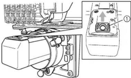
1 Remove the needle plate spacer.
natural_image
Technical diagram of a mechanical assembly with a close-up view of a component labeled (①), showing no readable text or symbols.① Needle plate spacer

Note
- Remove the needle plate spacer from the top. It may be damaged if it is pulled toward you with force.
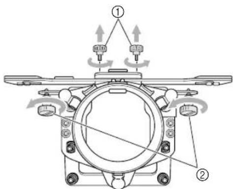
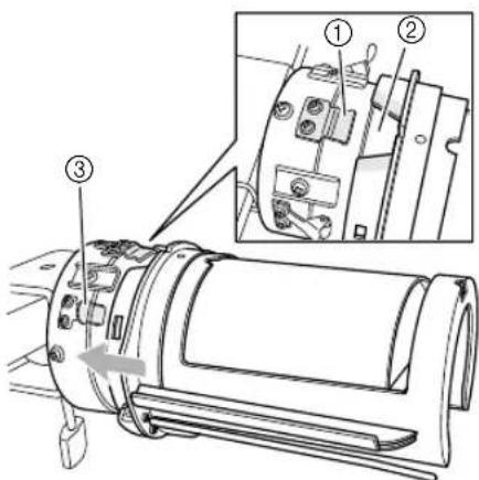
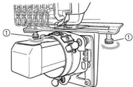
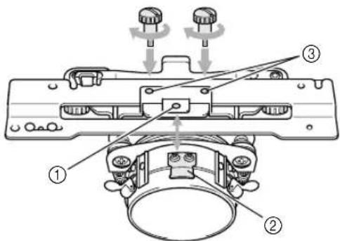
2 Loosen the two lower thumb screws.
text_image
Technical diagram of an electrical switch mechanism with labeled components and directional arrows① Thumb screw

Remove the two upper thumb screws.
text_image
Technical diagram of a mechanical assembly with labeled components and directional arrows indicating assembly steps.① Thumb screws

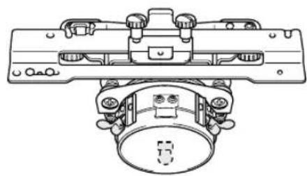
Remove the cylinder frame driver.
natural_image
Mechanical assembly diagram showing a motor and clamping mechanism (no text or labels)
Note
●Be careful that the cylinder frame driver does not hit any nearby parts, such as the presser foot and other machine parts.

Align the hole in the L-shaped mounting bracket for the cylinder frame driver with the centerline of the guiding plate, insert the two thumb screws removed in step ③ into the holes at the top, and then tighten the thumb screws.
text_image
Technical diagram of a mechanical assembly with numbered components and directional arrows indicating motion or assembly.① Hole in L-shaped mounting bracket
②Centerline of guiding plate
③Hole at the top
- Insert the thumb screws into the holes where the cylinder frame driver was originally installed (holes that the thumb screws were removed from in step 3).
The movable section of the cylinder frame driver is secured.

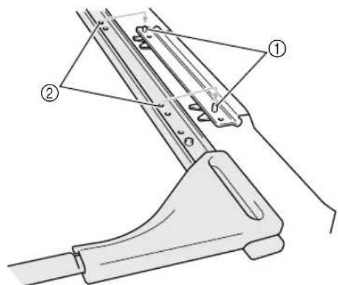
Align the holes in the embroidery frame holder with the pins on the X carriage, and then secure the embroidery frame holder with the two thumb screws.
text_image
Technical diagram of a mechanical device with labeled parts ① and ②, showing assembly or assembly steps.①Pins on the X carriage
②Holes in the embroidery frame holder

Secure the embroidery frame holder with the two thumb screws.
text_image
Technical diagram of a mechanical assembly with labeled component ①① Use the thumb screws included with the embroidery machine (thumb screws removed in step 1 on page 5).

Memo
● Using the disc-shaped screwdriver included with the embroidery machine, firmly tighten the thumb screws.
Additional digitizing information
In order to prevent pattern misalignment due to wrinkled or stretched fabric, observe the following precautions when creating embroidery data for the cylinder frame.

Sew underlay stitches.

natural_image
Simple cartoon illustration of a smiling mouse with ears and striped body (no text or symbols)
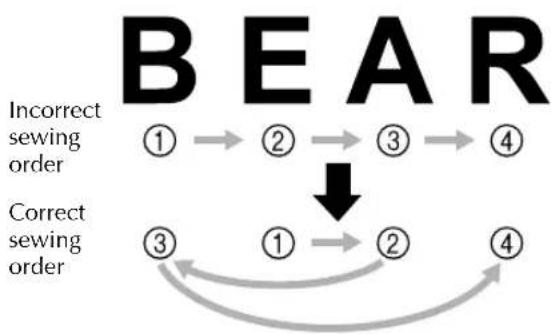
Specify the sewing order and sewing direction to start at the center of the embroidery pattern and sew toward the left and right sides.
With this embroidery machine, the order in which patterns are selected when they are combined is the order in which they will be sewn.
For the following example, select the patterns in the order "E" -> "A" -> "B" -> "R" to make the combined pattern "BEAR".
flowchart
graph TD
    A["①"] --> B["②"]
    B --> C["③"]
    C --> D["④"]
    E["③"] --> F["①"]
    F --> G["②"]
    G --> H["④"]
    style A fill:#000,stroke:#fff,color:#fff
    style B fill:#000,stroke:#fff,color:#fff
    style C fill:#000,stroke:#fff,color:#fff
    style D fill:#000,stroke:#fff,color:#fff
    style E fill:#000,stroke:#fff,color:#fff
    style F fill:#000,stroke:#fff,color:#fff
    style G fill:#000,stroke:#fff,color:#fff
    style H fill:#000,stroke:#fff,color:#fff

Note
●Do not sew from one end to the other, otherwise wrinkling or shrinkage may occur.

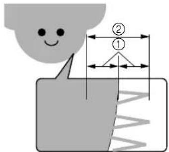
When sewing outlines of patterns, make sure that the stitch width of the satin stitching is at least 3 mm, and that the stitching overlaps the fabric by at least 1.5 mm. Also, make sure that there are no jumps of long stitches in the outlining on each region or letter.
text_image
Diagram illustrating a physical process with labeled components and dimensions, including a smiley face and wave pattern.① 1.5 mm or more
②3 mm or more

Note
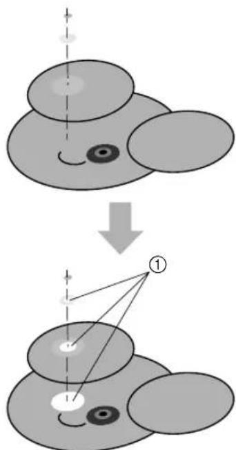
●Do not sew more than four overlapping layers.
text_image
Diagram illustrating a transformation or mapping process with labeled components and directional arrows① Create the data so that overlapping areas are not sewn.
natural_image
Technical line drawing of a mechanical component with coiled spring and housing (no text or symbols)②
natural_image
Technical line drawing of a mechanical assembly with no visible text or symbols③

natural_image
Technical line drawing of a cylindrical mechanical component with mounting base (no text or symbols)④

natural_image
Simple line drawing of a key with a handle and pointed tip (no text or symbols)⑤
natural_image
Simple line drawing of a key with a handle and pointed tip (no text or symbols)⑥

natural_image
Line drawing of a collared shirt with a button labeled 'β' on the side (no other text or symbols)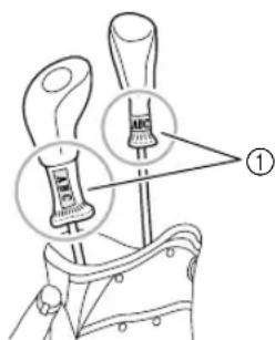
text_image
Diagram showing two labeled tools or components with arrows pointing to them, marked as figure ①.text_image
Diagram showing a fabric bag being folded into a woven blanket, with labeled parts ① and ②.① 155 mm (6 1/8 pouces)
text_image
Diagram of a bag with labeled parts and measurement arrows, showing two different sizes (① and ②) for size reference.text_image
Technical diagram of a mechanical assembly with labeled parts ① and ②text_image
Technical diagram of a mechanical bracket with labeled parts and an inset showing a detail view of the component.text_image
Technical diagram of a mechanical assembly with labeled parts and directional arrows indicating motion or assembly.text_image
Technical diagram of an electrical motor assembly with labeled parts ① and ②text_image
Technical diagram of a mechanical component with numbered parts and an inset showing a close-up view of a connector detail.text_image
Technical diagram of a mechanical component with numbered parts labeled ① and ②natural_image
Technical line drawing of a mechanical assembly with two screw fasteners and a bracket (no text or symbols)
natural_image
Mechanical assembly diagram showing a motor with rotating components and a hand operating it (no text or symbols present)text_image
Technical diagram of a mechanical assembly with numbered components labeled ①, ②, and ③.text_image
Technical diagram of a mechanical assembly with numbered components and close-up views of parts labeled ①, ②, and ③.text_image
Technical diagram of a mechanical device with labeled parts and an inset showing a mechanical component with motion arrows.text_image
Technical diagram of a mechanical assembly with labeled parts ① and ②, showing components like gears and a lever.①Vis hexagonales
②Clé Allen (3 mm) fournie
text_image
Technical diagram of a mechanical assembly with numbered components and an inset showing a close-up of a component detail.① Cercle
②Vis hexagonales

Remarque
natural_image
Technical diagram of a mechanical assembly with a close-up view of a component labeled (1), showing no readable text or symbols.text_image
Technical diagram of a mechanical device with numbered components and directional arrows indicating motion or movement.text_image
Technical diagram of a sewing machine with numbered components labeled ①, ②, and ③text_image
Technical diagram of a mechanical device with numbered components and an inset view showing internal components.natural_image
Technical illustration of a mechanical component with an inset showing a close-up view of a cylindrical part (no text or symbols present)text_image
Medical illustration showing anatomical or surgical views of a device with labeled parts and zoomed-in insets for detail.①Centre du motif
natural_image
Illustration of hands holding a device with a tool inserted (no text or symbols visible)
natural_image
Diagram of a mechanical device with labeled parts and an arrow indicating direction (no text or symbols present)① Attaches
text_image
Technical diagram showing mechanical assembly steps with numbered component and directional arrows indicating motionnatural_image
Diagram of a mechanical component with concentric rings and a central upward arrow (no text or symbols)
text_image
Technical diagram showing mechanical assembly with numbered components and directional arrow indicating motiontext_image
Technical diagram showing a device's internal components with numbered annotations and directional arrows indicating assembly or repair.① Fixations du support

Remarque
text_image
Diagram illustrating a mechanical assembly process with labeled parts and directional arrows indicating movement or force.① Attaches
natural_image
Technical line drawing of a sewing machine with a close-up inset showing the component (no text or symbols present)text_image
Technical diagram of a mechanical assembly with labeled parts, showing components like a motor and adjustment mechanism.text_image
Technical diagram of a mechanical assembly with labeled components and directional arrows indicating assembly steps.natural_image
Mechanical assembly diagram showing a motor and clamping mechanism (no text or labels)
Remarque
text_image
Technical diagram of a mechanical assembly with numbered parts and directional arrows indicating motion or assembly.text_image
Technical diagram of a mechanical device with labeled parts ① and ②, showing structural components and assembly.text_image
Technical diagram of a mechanical assembly with labeled component ①natural_image
Simple cartoon illustration of a mouse with ears and stripes (no text or symbols)
text_image
Diagram illustrating a physical process with labeled components and directional arrows, likely from an engineering or physics context.text_image
Diagram illustrating a transformation or mapping process of a cartoon character into two circular shapes, with labeled components and directional arrows.natural_image
Technical line drawing of a mechanical component with coiled spring and housing (no text or symbols)②
natural_image
Technical line drawing of a mechanical assembly with no visible text or symbols③
natural_image
Technical line drawing of a cylindrical mechanical device with mounting bracket (no text or symbols)④
natural_image
Simple line drawing of a key with a handle and pointed tip (no text or symbols)⑤

natural_image
Simple line drawing of a key-like object with a handle and pointed tip (no text or symbols)⑥
natural_image
Line drawing of a collared shirt with a button labeled 'β' on the side (no other text or symbols)
text_image
Diagram showing a tool with labeled parts and magnified views, including 'ABC' and 'BNC' annotations.text_image
Diagram showing a woven bag being placed on its side, with labeled parts ① and ② indicating different fabric types.① 155 mm (6 1/8 pulg.)
text_image
Diagram of a bag with labeled parts and measurement arrows, showing two different sizes (① and ②) for size reference.text_image
Technical diagram of a mechanical assembly with numbered components and directional arrows indicating motion or movement.text_image
Technical diagram of a mechanical component with labeled parts and an inset showing a disassembled assembly detail.text_image
Technical diagram of a mechanical assembly with labeled parts and directional arrows indicating motion or assembly.text_image
Technical diagram of an electrical component with labeled parts ① and ②, showing wiring connections and a motor mechanism.text_image
Technical diagram of a mechanical component with numbered parts and an inset view showing two labeled parts.text_image
Technical diagram of a mechanical component with numbered parts labeled ① and ②natural_image
Technical diagram of a mechanical assembly with two screw fasteners and a housing (no text or labels)
natural_image
Mechanical assembly diagram showing a motor with rotating components and a hand operating it (no text or symbols present)text_image
Technical diagram of a mechanical assembly with numbered components labeled ①, ②, and ③.text_image
Technical diagram of an electrical switch mechanism with labeled components and close-up insets showing motor and cable assembly.① Tornillos hexagonales
②Llave Allen suministrada (2,5 mm)
③Ajuste en el aro

Nota
text_image
Technical diagram of a mechanical assembly with labeled parts and an inset showing a mechanical component with motion indicators.text_image
Technical diagram of a mechanical assembly with labeled parts ① and ②, showing components like gears and a lever.①Tornillos hexagonales
②Llave Allen suministrada (3 mm)
text_image
Technical diagram of a mechanical assembly with numbered components and an inset showing a close-up of a mechanical component.① Aro
②Tornillos hexagonales

Nota
natural_image
Technical line drawing of a mechanical assembly with a close-up inset showing a component labeled (1), no readable text or symbols present.text_image
Technical diagram of a portable device with labeled parts including handle, base, and control paneltext_image
Technical diagram of a sewing machine with numbered components labeled ①, ②, and ③text_image
Technical diagram of a mechanical device with numbered components and an inset view showing internal parts.natural_image
Technical illustration of a mechanical component with an inset showing a close-up view of a cylindrical part (no text or symbols present)text_image
Medical illustration showing surgical procedure steps with labeled components and magnified viewsnatural_image
Illustration of hands holding a device with a tool inserted (no text or symbols visible)
text_image
Technical diagram of a mechanical device with labeled parts and directional arrow indicating motion or force①Pinzas
text_image
Technical diagram showing two-step assembly process with labeled component '①' and directional arrows indicating movement.natural_image
Diagram of a mechanical component with concentric rings and a central upward arrow (no text or symbols)
text_image
Technical diagram of a mechanical assembly with numbered components and directional arrow indicating motion or forcetext_image
Technical diagram showing mechanical assembly steps with numbered component and directional arrows indicating movementtext_image
Diagram illustrating a mechanical assembly with labeled parts and directional arrows indicating movement or force.① Pinzas
natural_image
Technical diagram of a mechanical assembly with a close-up view of a component labeled (①), showing no readable text or symbols.text_image
Technical diagram of a mechanical assembly with labeled parts, showing components like a motor and adjustment knobs.① Tornillo de mariposa

text_image
Technical diagram of a mechanical assembly with labeled parts and directional arrows indicating assembly steps① Tornillos de mariposa

natural_image
Mechanical assembly diagram showing a motor and clamping mechanism (no text or labels)
Nota
text_image
Technical diagram of a mechanical assembly with numbered components and directional arrows indicating motion or assembly.text_image
Technical diagram of a mechanical device with numbered components, likely for assembly or maintenance instructions.text_image
Technical diagram of a mechanical assembly with labeled component ①natural_image
Simple cartoon illustration of a mouse with ears and stripes (no text or symbols)