
GWH5 - Heating Pelgrim - Free user manual and instructions
Find the device manual for free GWH5 Pelgrim in PDF.

| Brand | Pelgrim |
| Model | GWH5 |
| Product type | Wall-mounted gas heater |
| Category | Heating |
| Approximate dimensions (H x W x D) | 600 x 400 x 200 mm |
| Approximate weight | 8 kg |
| Power supply | Natural gas or propane (convertible) |
| Gas pressure | See rating plate |
| Rated power | Approx. 5 kW (depending on gas type) |
| Ignition type | Piezo electric |
| Thermostat | Integrated, positions 1 to 7 |
| Thermocouple safety | Yes |
| Installation required | Only against exterior wall by certified installer |
| Periodic maintenance | At least once a year by a professional |
| Minimum distance to curtains | 15 cm above the mantle |
| Available spare parts | Glass kit (20900081), pilot light kit (20900082), exhaust kit (20900084) |
| Packaging materials | Cardboard, polystyrene, wood, plastic, paper |
Frequently Asked Questions - GWH5 Pelgrim
User questions about GWH5 Pelgrim
0 question about this device. Answer the ones you know or ask your own.
Ask a new question about this device
Download the instructions for your Heating in PDF format for free! Find your manual GWH5 - Pelgrim and take your electronic device back in hand. On this page are published all the documents necessary for the use of your device. GWH5 by Pelgrim.
USER MANUAL GWH5 Pelgrim
Manual wall-mounted heater
This wall-mounted heater has been specially developed for mounting on an external wall. The flue gases are vented directly to the outside through the external wall. The wall-mounted heater is fully protected by means of a thermo-electric pilot-light safeguard to prevent accidental outflow of gas from the main burner.
introduction
If you read this manual, you will soon become acquainted with the possibilities this heater offers. The manual contains advice on safe use and information on installation, operation and maintenance of the heater.
This manual has been compiled on the assumption that the heater will be installed by an authorised gas installer who is familiar with national and local regulations.
Keep this book in a safe place, so that future users can benefit from this information.
table of contents
introduction 1
safety 2
positioning 3
installation 4-5
conversion 6
use 7
cleaning 8
faults 9
disposal of packaging and appliance 9
parts list I
technical information II - IX
safety
This heater may only be positioned and installed by an authorised installer.
The housing of this heater can reach high temperatures. Be careful therefore with children: keep them away from the heater or place a guard around the heater.
- Never place objects on the heater when it is working.
Never use the heater to dry clothes, towels, etc.; if the housing is covered, very high temperatures will develop inside the housing.
Since the rising air above the heater is at a fairly high temperature,curtains or 'nats' must not be positioned directly above the heater. Do not install the heater below a window ledge made of combustible material. The minimum distance between the housing and curtains or a combustible window ledge above the housing should be 15 cm .
Periodic maintenance (at least once a year, for example at the start of the heating season) by an authorised person is advisable in order to ensure effective, safe operation of this heater.
If, for whatever reason, the heater has gone out, wait for at least 5 minutes before re-lighting the appliance.
Use an approved gas tap to connect the heater to the gas main.
The heater may only be repaired using original parts.
Burnt dust causes an unpleasant smell and also results in discoloration of walls and ceilings. Although such discoloration can never be entirely prevented, it can be minimised by keeping the room, the housing and the interior free from dust.
gas type and pressure
The hearth is set to the nominal load, in accordance with the category stated on the identification plate, and sealed at the factory. The pilot light is set to the correct flow. See the technical data for this information. Check that the data on the identification plate corresponds to the local gas type and pressure. Check that the data on the identification plate correspond to the type and voltage of the current in your building. The identification plate is located on the rear panel of the heater.
positioning
This wall-mounted heater may only be positioned against an external wall as the products of combustion have to be vented direct to the outside air.
The unit may only be installed by an authorised installer and in accordance with national and local regulations.
The heater should preferably not be positioned in a corner as the burner has to be capable of being removed from the heater for periodic maintenance.
Do not install the external wall grille too close to a windowsill (see also 'safety').
length of inlet and outlet pipe
Wall thickness: minimum 70 mm
Length of inlet pipe: as wall thickness.
Length of outlet pipe: wall thickness + 70 mm, maximum length 600 mm.
installing the appliance
The mounting plate supplied with this appliance will serve as a template and as an assembly unit for the wall vent and the internal mechanism. Holes A, B and C in fig. 2 are for the mounting screws. The minimum distance from the bottom of this mounting plate to the floor must be 20mm (295 mm from the floor to the bottom of the vent-pipe hole).
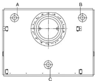
fig.2
The hole for the wall vent-pipe must be round and have an internal diameter of 153mm . It is advisable to drill this hole or arrange for it to be drilled.
To avoid ingress of rain this hole must be level and must certainly not slope downwards towards the inside.
If the heater is installed against a wall made from combustible material, the diameter of the wall opening must be 180mm and a sheet of incombustible material, containing a 153mm diameter hole, must be installed to cover the entire surface behind the mounting plate. It is advisable to mount this sheet 2 to 3mm clear of the wall.
When determining the place at which the appliance is to be installed, account must also be taken of the conditions indicated in the section on 'positioning'.
Draw the holes for the key bolts and the opening for the wall vent pipe using the mounting plate. Make sure that the plate is level.
Drill the holes.
Cut the inlet pipe (largest diameter) to size.
Place the key bolts in the holes drilled in the wall.
Secure the mounting plate to the wall.
Using a spirit level check that the mounting plate is horizontal and tighten the mounting screws.
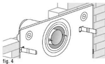
- Secure the inlet pipe to the flue grille. Screw the tensioning members into the wall grille. Then slide the grille on to the inlet pipe.
Push the pipe through the hole in the wall from the outside.
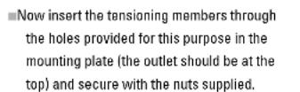
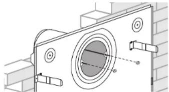
fig. 3
Make sure that the stud bolts do not protrude too far (maximum 10 mm including nut). Saw off the surplus length.
Now cut the aluminium outlet pipe to size (wall thickness + 70 mm).
Insert the outlet pipe into the opening provided for that purpose in the wall grille.
Take the internal mechanism and place the fibreglass packing around the air inlet.
Place the internal mechanism with the base resting on the lower supports.
Slide the internal mechanism with the support guides around the lips on the mounting plate.
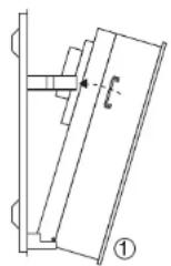
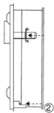
fig.5
Slide the outlet from the internal mechanism on to the flue pipe.
Slide the internal mechanism horizontally backwards until the pins on the base of the internal mechanism engage with the horizontal supports. Secure the internal mechanism by screwing the support guides tight at the top.
Place the casing vertically against the wall and the mounting plate, so that the projections fit into the slotted holes. Lower the casing vertically.
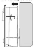
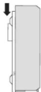
fig.6
connection to the gas supply
Avoid straining the regulator tap when connecting. Check gas connections for leaks. Check the operation of the heater and explain it to the user.
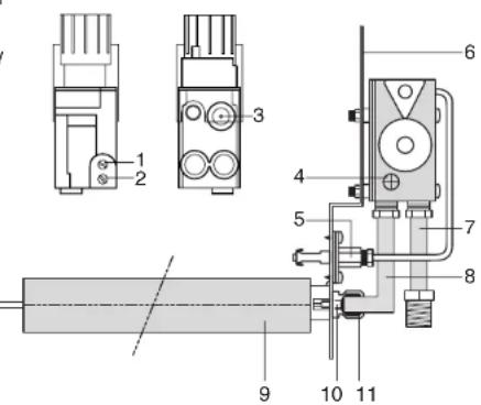
converting to a different type of gas
Check that the values indicated on the components correspond with the values in the accompanying table.
Close the gas tap.
Replace the pressure regulator for natural gas with the adjusting screw for propane (or vice versa).
Replace the main injection nozzle with the nozzle from the conversion kit.
Replace the pilot light injection nozzle with the nozzle from the conversion kit.
Replace the low-setting restrictor with the low-setting restrictor from the conversion kit.
- Measurement point for burner pressure
- Measurement point for supply pressure
- Pressure regulator or adjusting screw
- Low-setting restrictor
- Pilot light
- Mounting bracket
- Supply pipe
- Burner pipe
- Main burner
- Injection nozzle
- Taper ring and coupling nut
Replace the settings plate with the settings place from the conversion kit.
Adjust the burner pressure as per the table supplied with the conversion kit. In the case of appliances without pressure regulator pay particular attention to whether, with the appliance turned on full, the supply pressure corresponds with the appliance's rated inlet pressure.
Check all connections previously dismantled for leaks.
lighting
Open the gas tap.
Turn control knob B to position and press it in. Gas will now flow to the pilot light burner.
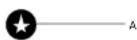
fig.8
Press ignition button A. A spark will now jump to the pilot light burner. Keep the ignition pressed in until the pilot light ignites, then keep knob B pressed in for approximately a further 10 seconds.
If the pilot light now goes out again, the preceding action has to be repeated and ignition button B must be held in for a little longer.
Once the pilot light is lit you can select a setting between 1 and 7 with thermostat knob B.
switching off
If you turn the control knob to the position between 1, only the pilot light will burn. This is also the frost-protection position, i.e. at this setting the main burner will only be switched on at a very low ambient temperature to keep the room frost-free. You should therefore leave the pilot light on during the heating season.
Turn control knob B to position .heater is now completely switched off.
maintenance and cleaning
The heater should be cleaned and checked annually by an authorised installer.
Check that:
-the gas supply is airtight;
-the regulator and the thermocouple circuit function properly and that the burner ignites properly.
Clean (if necessary):
-the pilot system;
-theburner;
-the combustion chamber;
-the flue gas exhaust.
cleaning the burner
Once the heater has cooled down sufficiently, the burner can be cleaned.
Burnt dust gives off an unpleasant smell and also results in discoloration of walls and ceilings. Although such discoloration can never be entirely avoided, it can be restricted to a minimum by keeping the room, the housing and the internal mechanism free of dust.
Discoloration of the housing can be prevented by cleaning it regularly with soap and water. After cleaning, rinse thoroughly with clean water and rub dry. Never use aggressive or abrasive cleaning agents for the housing.
faults
Heater fails to light or extinguish.
Causes:
Air in supply pipe (after appliance has been out of operation).
Vent.
- Insufficient gas pressure.
Check that the gas tap is open and check the gas line to see if it is dirty.
- The pilot light is dirty.
Clean the burner carefully with a vacuum cleaner.
- The thermocouple contact does not engage properly.
Check the thermocouple circuit.
disposing of the packaging and appliancel
The appliance packaging is recyclable. The packaging could include the following materials:
card board;
CFC-free foam (soft);
- wood
- plastic;
- paper.
These materials should be disposed responsibly and in conformity with government regulations.
Information on how to responsibly dispose of discarded appliances can be obtained from the local authorities.
brander GWH 2 / burner GWH 3 / brûlour GWH 2 20900085
set LPG NL GWH 2/set LPG NL GWH 2/jeu GPL NL GWH 2 20900086
set LPG our GWH 2/set LPG our GWH 2/jeu GPL our GWH 2 20900087
set aardgas NL GWH 2 / set NG NL GWH 2 / jeu gaz naturel NL GWH 2 20900088
set aardgas eur GWH 2/set NG eur GWH 2/jeu gaz naturel eur GWH 2 20900089
brander GWH 3/ burner GWH 3/ bruleur GWH 3 20900090
set LPG NL GWH 3/set LPG NL GWH 3/jeu GPL NL GWH 3 20900091
set LPGeur GWH 3/set LPGeur GWH 3/jeu GPLeur GWH 320900092
setaardgas NL GWH 3/set NG NL GWH 3/jeu gaz naturel NL GWH 3 20900093
set aardgaseur GWH 3/set NGeur GWH 3/jeu gaz naturel eur GWH 3 20900094
brander GWH 4 / burner GWH 34/ bruleur GWH 4 20900095
set LPGNL GWH 4/set LPGNL GWH 4/jeu GPL NL GWH 4 20900096
set LPGeur GWH4/set LPGeur GWH4/jeu GPLeur GWH4 20900097
set aardgas NL GWH 4 / sat NG NL GWH 4 / jeu gaz naturel NL GWH 4 20900098
set aardgaseur GWH 4/set NGeur GWH 4/jeu gaz naturel eur GWH 4 20900099
brander GWH 5/burner GWH 5/bruleur GWH 5 20900100
set LPG NL GWH 5/set LPG NL GWH 5/jeu GPL NL GWH 5 20900101
set LPGeur GWH 5/set LPGeur GWH 5/jeu GPLeur GWH 520900102
set aardgas NL GWH 5 / sat NG NL GWH 5 / jeu gaz naturel NL GWH 5 20900103
set aardgaseur GWH 5/set NGeur GWH 5/jeu gaz naturel eur GWH 520900104
Technische gegevens / technical data / fiche technique GWH 2
| Land / country/pays | NL BE/FR | DE DE/LU AT/ES/GB/HU NL/HU NL BE/IT/PT/ES/FR/GB | BE/ES/FR/AT/DE | IT/PT GB/IT/PT | G31-30 | G30-29 | G30-29 | G31-37 | G30-50 | ||||
| G25-25 | G20-20 | G20-20 | G20-20 | G20-25 | G31-30 | G30-29 | G31-37 | G30-50 | |||||
| Soort gas en toevoerdruk/gastype-supply pressure/type gaz pression d'alimentation | I2L | I2E+ | I2ELL | I2E | I2H | I3P | I3B/P | I3+ | I3P | ||||
| Cat. | C11 | C11 | C11 | C11 | C11 | C11 | C11 | C11 | C11 | C11 | |||
| Type apparaat/appliance type/type d'appareil | |||||||||||||
| Nominale warmte toevoer/nominal heat input/apport calorifique nominal (Hi) | [kW] | 2,5 | 2,5 | 2,5 | 2,5 | 2,5 | 2,5 | 2,5 | 2,5 | 2,5 | 2,5 | ||
| Rendementsklasse/efficiency class/classe de rendement | 1 | 1 | 1 | 1 | 1 | 1 | 1 | 1 | 1 | 1 | |||
| Soort gas/gas type/type de gaz | G25 | G20 | G25 | G20 | G25 | G20 | G20 | G20 | G31 | G30 | G31 | G30 | |
| Toevoerdruk/supply pressure/pression d'alimentation | [mbar] | 25 | 20 | 25 | 20 | 20 | 20 | 20 | 25 | 30 | 29 | 29 | 37 |
| Gasdebiet bij nominale toevoer/gas flow at nominal input/occuloment gazeux à l'entrée nominale | [l/h] | 290 | 260 | 260 | 290 | 260 | 260 | 260 | 100 | 75 | 75 | 100 | |
| Branderdruk bij nominale toevoer/burner pressure at nominal input/pression brûleur à l'entrée nominale | [mbar] | 10,5 | 7 | 8,8 | 7 | 10,5 | 7 | 7 | 7 | 20 | 15 | 15 | 18,5 |
| Insptuer brandender/druck/injector size/taille injecteur | [mm] | 1,6 | 1,6 | 1,6 | 1,6 | 1,6 | 1,6 | 1,6 | 1,6 | 1 | 1 | 1 | 1 |
| Branderdruk/burner pressure/pression brûleur (min.) | [mbar] | 1,6 | 1,3 | 1,3 | 1,6 | 1,3 | 1,3 | 1,3 | 3 | 2,2 | 2,2 | 3 | |
| Schroof/scrow/vis (min.) | 1,1 | 1,1 | 1,1 | 1,1 | 1,1 | 1,1 | 0,6 | 0,6 | 0,6 | 0,6 | |||
| Waakvlamunit/pilot flame unit/unité flamme pilote | Sit 140 | Sit 140 | Sit 140 | Sit 140 | Sit 140 | Sit 140 | Sit 140 | Sit 140 | Sit 140 | Sit 140 | |||
| Waakvlaminspuieter/pilot flame injector/injecteur flamme pilote | 27 | 27 | 27 | 27 | 27 | 27 | 14 | 14 | 14 | 14 | |||
| Rookgas/exhaust gasses/gaz brûlés | Vol. [m3/h] | 15 | 15 | 15 | 15 | 15 | 15 | 15 | 15 | 15 | 15 | ||
| CO2 [%] | 3,9 | 4 | 4 | 4 | 4 | 4 | 4,7 | 5,3 | 5,3 | 4,7 | |||
| CO [ppm] | 0 | 0 | 0 | 0 | 0 | 0 | 0 | 0 | 0 | 0 | |||
| Temp. [°C] | 240 | 230 | 230 | 230 | 230 | 230 | 230 | 245 | 245 | 230 | |||
| NOx [mg/xWh] | 240 | 265 | 265 | 265 | 265 | 265 | 324 | 322 | 322 | 324 | |||
| NOx class | 3 | 3 | 3 | 3 | 3 | 3 | 3 | 3 | 3 | 3 | |||
| Regeling/control/contrôle | eurosit | eurosit | eurosit | eurosit | eurosit | eurosit | eurosit | eurosit | eurosit | eurosit | |||
| Drukregelaar/pressure regulator/régulator de pression | yes | no | yes | yes | yes | yes | no | no | no | no | |||
| Gasinlaataansluiting/gas inlet connection/conNECTION entrée gaz | 1/2* | 1/2* | 1/2* | 1/2* | 1/2* | 1/2* | 1/2* | 1/2* | 1/2* | 1/2* | |||
| Schoorsteenaansluiting/flue connection/conNECTION conduit | 100-150 | 100-150 | 100-150 | 100-150 | 100-150 | 100-150 | 100-150 | 100-150 | 100-150 | 100-150 | |||
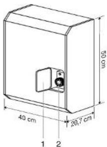
| Hoopte/height/hauteur | [mm] | 500 | 500 | 500 | 500 | 500 | 500 | 500 | 500 | 500 | 500 | ||
| Breodte/width/largeur | [mm] | 400 | 400 | 400 | 400 | 400 | 400 | 400 | 400 | 400 | 600 | ||
| Diepte/deep/th profondeur | [mm] | 207 | 207 | 207 | 207 | 207 | 207 | 207 | 207 | 207 | 207 | ||
Technische gegevens / technical data / fiche technique GWH 3
| Land / country/pays | NL BE/FR | DE DE/LU AT/ES | GB/HU NL/HU NL BE/IT/PT/ES/FR/GB | BE/ES/FR/AT/DE | IT/PT GB/IT/PT | ||||||||
| G25-25 | G20-20 | G20-20 | G20-20 | G20-20 | G20-20 | G20-25 | G31-30 | G30-29 | G30-29 | G31-37 | G30-50 | ||
| Soort gas en toevoerdruk/gastype-supply pressure/type gaz pression d'alimentation | I2L | I2E+ | I2ELL | I2E | I2H | I3P | I3B/P | I3+ | I3P | I3B/P | |||
| Cat. | C11 | C11 | C11 | C11 | C11 | C11 | C11 | C11 | C11 | C11 | C11 | C11 | |
| Type apparaat/appliance type/type d'appareil | |||||||||||||
| Nominale warmte toevoer/nominal heat input/ | |||||||||||||
| apport calorifique nominal (Hi) | [kW] | 3,5 | 3,5 | 3,5 | 3,5 | 3,5 | 3,5 | 3,5 | 3,5 | 3,5 | 3,5 | 3,5 | 3,5 |
| Rendementsklasse/efficiency class/ | |||||||||||||
| classe de rendement | 1 | 1 | 1 | 1 | 1 | 1 | 1 | 1 | 1 | 1 | 1 | 1 | |
| Soort gas/gas type/type de gaz | G25 | G20 G25 | G20 G25 | G20 G20 | G20 G20 | G20 G20 | G31 G30 | G30 G30 | G31 G31 | G31 G31 | G31 G31 | G30 G30 | |
| Toevoerdruk/supply pressure/pression d'alimentation | [mbar] | 25 | 20 25 | 20 | 20 | 20 | 20 | 25 | 30 | 29 | 29 | 37 | 50 |
| Gasdebiet bij nominale toevoer/gas flow at nominal input/ecculoment gazeux à l'entrée nominale | [l/h] | 420 | 360 | 360 | 420 | 360 | 360 | 360 | 140 | 110 | 110 | 140 | 110 |
| Branderdruk bij nominale toevoer/burner pressure at nominal input/pression brûleur à l'entrée nominale | [mbar] | 12,8 | 8,1 10,1 | 8,1 | 12,8 | 8,1 | 8,1 | 8,1 | 27 | 25 | 25 | 32 | 25 |
| Insptuer brandender.dk/Injector size/taille injecteur | [mm] | 1,85 | 1,85 1,85 | 1,85 | 1,85 | 1,85 | 1,85 | 1,85 | 1,05 | 1 | 1 | 1 | 1 |
| Branderdruk/burner pressure/pression brûleur (min.) | [mbar] | 2,7 | 1,8 | 1,8 | 1,8 | 1,8 | 1,8 | 4,3 | 4,3 | 4,3 | 6,3 | 4,3 | |
| Schroof/scrow/vis (min.) | 1,4 | 1,4 | 1,4 | 1,4 | 1,4 | 1,4 | 0,7 | 0,7 | 0,7 | 0,7 | 0,7 | ||
| Waakvlamunit/pilot flame unit/unité flamme pilote | Sit 140 | Sit 140 | Sit 140 | Sit 140 | Sit 140 | Sit 140 | Sit 140 | Sit 140 | Sit 140 | Sit 140 | Sit 140 | ||
| Waakvlaminspuieter/pilot flame injector/ | |||||||||||||
| injecteur flamme pilote | 27 | 27 | 27 | 27 | 27 | 27 | 27 | 14 | 14 | 14 | 14 | 14 | |
| Rookgas/exhaust gasses/gaz brûlés | Vol. [m3/h] | 13 | 13 | 13 | 13 | 13 | 13 | 13 | 13 | 13 | 13 | 13 | 13 |
| CO2 [%] | 7,3 | 7,3 | 7,3 | 7,3 | 7,3 | 7,3 | 7,3 | 7,4 | 7,4 | 7,4 | 7,4 | 7,4 | |
| CO [ppm] | 0 | 0 | 0 | 0 | 0 | 0 | 0 | 0 | 0 | 0 | 0 | 0 | |
| Temp. [°C] | 280 | 280 | 280 | 280 | 280 | 280 | 280 | 250 | 250 | 250 | 250 | 250 | |
| NOx [mg/xWh] | 190 | 203 | 203 | 203 | 203 | 203 | 203 | 206 | 243 | 243 | 206 | 243 | |
| NOx class | 3 | 3 | 3 | 3 | 3 | 3 | 3 | 3 | 3 | 3 | 3 | 3 | |
| Regeling/control/contrôle | eurosit | eurosit | eurosit | eurosit | eurosit | eurosit | eurosit | eurosit | eurosit | eurosit | eurosit | eurosit | |
| Drukregelaar/pressure regulator/régulator de pression | yes | no | yes | yes | yes | yes | no | no | no | no | no | no | |
| Gasinfaataansluiting/gas inlet connection/connexion entrée gaz | 1/2* | 1/2* | 1/2* | 1/2* | 1/2* | 1/2* | 1/2* | 1/2* | 1/2* | 1/2* | 1/2* | 1/2* | |
| Schoorsteenaansluiting/flue connection/connexion conduit | 100-150 | 100-150 | 100-150 | 100-150 | 100-150 | 100-150 | 100-150 | 100-150 | 100-150 | 100-150 | 100-150 | 100-150 | |
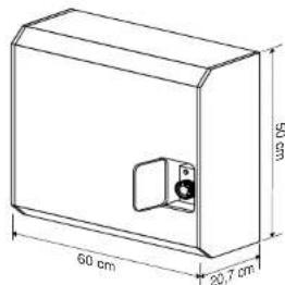
| Hoopte/height/hauteur | [mm] | 500 | 500 | 500 | 500 | 500 | 500 | 500 | 500 | 500 | 500 | 500 | 500 |
| Breodte/width/largeur | [mm] | 600 | 600 | 600 | 600 | 600 | 600 | 600 | 600 | 600 | 600 | 600 | 600 |
| Diepte/deep/th profondeur | [mm] | 207 | 207 | 207 | 207 | 207 | 207 | 207 | 207 | 207 | 207 | 207 | 207 |
Technische gegevens / technical data / fiche technique GWH 4
| Land / country/pays | NL BE/FR | DE DE/LU AT/ES | GB/HU NL/HU NL BE/IT/PT/ES/FR/GB | BE/ES/FR/AT/DE | IT/PT GB/IT/PT | |||||||
| G25-25 | G20-20 | G20-20 | G20-20 | G20-20 | G20-20 | G20-25 | G31-30 | G30-29 | G30-29 | G31-37 | ||
| Soort gas en toevoerdruk/gastype-supply pressure/type gaz pression d'alimentation | I2L | I2E+ | I2ELL | I2E | I2H | I3P | I3B/P | I3+ | I3P | I3B/P | ||
| Cat. | C11 | C11 | C11 | C11 | C11 | C11 | C11 | C11 | C11 | C11 | C11 | |
| Type apparaat/appliance type/type d'appareil | ||||||||||||
| Nominale warmte toevoer/nominal heat input/ | ||||||||||||
| apport calorifique nominal (Hi) | [kW] | 4,7 | 4,7 | 4,7 | 4,7 | 4,7 | 4,7 | 4,7 | 4,7 | 4,7 | 4,7 | 4,7 |
| Rendementsklasse/efficiency class/ | ||||||||||||
| classe de rendement | 1 | 1 | 1 | 1 | 1 | 1 | 1 | 1 | 1 | 1 | 1 | |
| Soort gas/gas type/type de gaz | G25 | G20 G25 | G20 G25 | G20 G20 | G20 G20 | G20 G20 | G31 G31 | G30 G30 | G30 G31 | G31 G31 | G30 G30 | |
| Toevoerdruk/supply pressure/pression d'alimentation | [mbar] | 25 | 20 25 | 20 | 20 | 20 | 20 | 25 | 30 | 29 | 29 | 37 |
| Gasdebiet bij nominale toevoer/gas flow at nominal input/ecculoment gazeux à l'entrée nominale | [l/h] | 580 | 490 | 490 | 580 | 490 | 490 | 490 | 190 | 140 | 140 | 190 |
| Branderdruk bij nominale toevoer/burner pressure at nominal input/pression brûleur à l'entrée nominale | [mbar] | 11,5 | 8 10 | 8 | 11,5 | 8 | 8 | 8 | 20 | 24 | 24 | 33 |
| Insptuer brandender.dk/Injector size/taille injecteur | [mm] | 2,2 | 2,2 2,2 | 2,2 | 2,2 | 2,2 | 2,2 | 2,2 | 1,3 | 1,2 | 1,2 | 1,2 |
| Branderdruk/burner pressure/pression brûleur [min.] | [mbar] | 1,6 | 1,4 | 1,4 | 1,6 | 1,4 | 1,4 | 1,4 | 2,2 | 4 | 4 | 5,4 |
| Schroof/scrow/vis [min.] | 1,4 | 1,4 | 1,4 | 1,4 | 1,4 | 1,4 | 0,8 | 0,8 | 0,8 | 0,8 | ||
| Waakvlamunit/pilot flame unit/unité flamme pilote | Sit 140 | Sit 140 | Sit 140 | Sit 140 | Sit 140 | Sit 140 | Sit 140 | Sit 140 | Sit 140 | Sit 140 | ||
| Waakvlaminspuiiter/pilot flame injector/ | ||||||||||||
| injecteur flamme pilote | 27 | 27 | 27 | 27 | 27 | 27 | 27 | 14 | 14 | 14 | 14 | |
| Rookgas/exhaust gasses/gaz brûlés | Vol. [m3/h] | 16 | 16 | 16 | 16 | 16 | 16 | 16 | 16 | 16 | 16 | 16 |
| CO2 [%] | 8,4 | 7,9 | 7,9 | 7,9 | 7,9 | 7,9 | 7,9 | 8,65 | 8,6 | 8,6 | 8,6 | |
| CO [ppm] | 0 | 0 | 0 | 0 | 0 | 0 | 0 | 0 | 0 | 0 | 0 | |
| Temp. [°C] | 335 | 334 | 334 | 334 | 334 | 334 | 334 | 330 | 318 | 318 | 330 | |
| NOx [mg/xWh] | 160,6 | 181,8 | 181,8 | 181,8 | 181,8 | 181,8 | 181,8 | 226,6 | 243,7 | 243,7 | 226,6 | |
| NOx class | 3 | 3 | 3 | 3 | 3 | 3 | 3 | 3 | 3 | 3 | 3 | |
| Regeling/control/contrôle | eurosit | eurosit | eurosit | eurosit | eurosit | eurosit | eurosit | eurosit | eurosit | eurosit | eurosit | |
| Drukregelaar/pressure regulator/régulator de pression | yes | no | yes | yes | yes | yes | no | no | no | no | no | |
| Gasinfaataansluiting/gas inlet connection/connexion entrée gaz | 1/2* | 1/2* | 1/2* | 1/2* | 1/2* | 1/2* | 1/2* | 1/2* | 1/2* | 1/2* | 1/2* | |
| Schoorsteenaansluiting/flue connection/connexion conduit | 100-150 | 100-150 | 100-150 | 100-150 | 100-150 | 100-150 | 100-150 | 100-150 | 100-150 | 100-150 | 100-150 | |
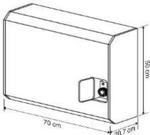
| Hoopte/height/hauteur | [mm] | 500 | 500 | 500 | 500 | 500 | 500 | 500 | 500 | 500 | 500 | 500 |
| Breodte/width/largeur | [mm] | 700 | 700 | 700 | 700 | 700 | 700 | 700 | 700 | 700 | 700 | 700 |
| Diepte/deep/th profondeur | [mm] | 207 | 207 | 207 | 207 | 207 | 207 | 207 | 207 | 207 | 207 | 207 |
Technische gegevens / technical data / fiche technique GWH 5
| Land / country/pays | NL BE/FR | DE DE/LU AT/ES | GB/HU NL/HU NL BE/IT/PT/ES/FR/GB | BE/ES/FR/AT/DE | IT/PT GB/IT/PT | ||||||||
| G25-25 | G20-20 | G20-20 | G20-20 | G20-20 | G20-20 | G20-25 | G31-30 | G30-29 | G30-29 | G31-37 | G30-50 | ||
| Soort gas en toevoerdruk/gastype-supply pressure/type gaz pression d'alimentation | I2L | I2E+ | I2ELL | I2E | I2H | I3P | I3B/P | I3+ | I3P | I3B/P | |||
| Cat. | C11 | C11 | C11 | C11 | C11 | C11 | C11 | C11 | C11 | C11 | C11 | C11 | |
| Type apparaat/appliance type/type d'appareil | |||||||||||||
| Nominale warmte toevoer/nominal heat input/ | |||||||||||||
| apport calorifique nominal (Hi) | [kW] | 5,8 | 5,8 | 5,8 | 5,8 | 5,8 | 5,8 | 5,8 | 5,8 | 5,8 | 5,8 | 5,8 | 5,8 |
| Rendementsklasse/efficiency class/ | |||||||||||||
| classe de rendement | 1 | 1 | 1 | 1 | 1 | 1 | 1 | 1 | 1 | 1 | 1 | 1 | |
| Soort gas/gas type/type de gaz | G25 | G20 G25 | G20 G25 | G20 G20 | G20 G20 | G20 G20 | G31 G30 | G30 G30 | G31 G31 | G31 G31 | G31 G31 | G30 G30 | |
| Toevoerdruk/supply pressure/pression d'alimentation | [mbar] | 25 | 20 25 | 20 20 | 20 20 | 20 20 | 20 20 | 30 29 | 29 29 | 37 37 | 37 37 | 50 50 | |
| Gasdebiet bij nominale toevoer/gas flow at nominal input/ecculoment gazeux à l'entrée nominale | [l/h] | 690 | 590 | 590 | 690 | 590 | 590 | 230 | 180 | 180 | 230 | 180 | |
| Branderdruk bij nominale toevoer/burner pressure at nominal input/pression brûleur à l'entrée nominale | [mbar] | 24 | 15 18,8 | 15 15 | 24 | 15 15 | 15 15 | 24 18 | 18 18 | 23 24 | 18 18 | 18 18 | |
| Insptuer brandender/druk/injector size/taille injecteur | [mm] | 2 | 2 2 | 2 | 2 | 2 | 2 | 1,4 | 1,4 | 1,4 | 1,4 | 1,4 | 1,4 |
| Branderdruk/burner pressure/pression brûleur (min.) | [mbar] | 3,5 | 2,2 | 2,2 | 3,5 | 2,2 | 2,2 | 2,1 | 1,6 | 1,6 | 2,1 | 1,6 | |
| Schroof/scrow/vis (min.) | 1,4 | 1,4 | 1,4 | 1,4 | 1,4 | 1,4 | 0,8 | 0,8 | 0,8 | 0,8 | 0,8 | 0,8 | |
| Waakvlamunit/pilot flame unit/unité flamme pilote | Sit 140 | Sit 140 | Sit 140 | Sit 140 | Sit 140 | Sit 140 | Sit 140 | Sit 140 | Sit 140 | Sit 140 | Sit 140 | ||
| Waakvlaminspuieter/pilot flame injector/ | |||||||||||||
| injecteur flamme pilote | 27 | 27 | 27 | 27 | 27 | 27 | 14 | 14 | 14 | 14 | 14 | ||
| Rookgas/exhaust gasses/gaz brûlés | Vol. [m3/h] | 22 | 22 | 22 | 22 | 22 | 22 | 22 | 22 | 22 | 22 | 22 | |
| CO2 [%] | 7,54 | 7,52 | 7,52 | 7,52 | 7,52 | 7,52 | 8,1 | 8,1 | 8,1 | 8,1 | 8,1 | ||
| CO [ppm] | 0 | 0 | 0 | 0 | 0 | 0 | 0 | 0 | 0 | 0 | 0 | ||
| Temp. [°C] | 344 | 338 | 338 | 338 | 338 | 338 | 333 | 328 | 328 | 233 | 328 | ||
| NOx [mg/xWh] | 247 | 266 | 266 | 266 | 266 | 266 | 318 | 318 | 318 | 318 | 318 | ||
| NOx class | 2 | 1 | 1 | 1 | 1 | 1 | 2 | 2 | 2 | 2 | 2 | ||
| Regeling/control/contrôle | eurosit | eurosit | eurosit | eurosit | eurosit | eurosit | eurosit | eurosit | eurosit | eurosit | eurosit | ||
| Drukregelaar/pressure regulator/régulator de pression | / | no | yes | yes | yes | yes | no | no | no | no | no | ||
| Gasinfaataansluiting/gas inlet connection/connexion entrée gaz | 1/2* | 1/2* | 1/2* | 1/2* | 1/2* | 1/2* | 1/2* | 1/2* | 1/2* | 1/2* | 1/2* | ||
| Schoorsteenaansluiting/flue connection/connexion conduit | 100-150 | 100-150 | 100-150 | 100-150 | 100-150 | 100-150 | 100-150 | 100-150 | 100-150 | 100-150 | 100-150 | ||
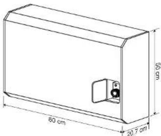
| Hoopte/height/hauteur | [mm] | 500 | 500 | 500 | 500 | 500 | 500 | 500 | 500 | 500 | 500 | 500 | |
| Breodte/width/largeur | [mm] | 800 | 800 | 800 | 800 | 800 | 800 | 800 | 800 | 800 | 800 | 800 | |
| Diepte/deep/th profondeur | [mm] | 207 | 207 | 207 | 207 | 207 | 207 | 207 | 207 | 207 | 207 | 207 | |


- introduction
- table of contents
- safety
- gas type and pressure
- positioning
- length of inlet and outlet pipe
- installing the appliance
- connection to the gas supply
- converting to a different type of gas
- lighting
- switching off
- maintenance and cleaning
- cleaning the burner
- faults
- Heater fails to light or extinguish.
- disposing of the packaging and appliancel
Brand : Pelgrim
Model : GWH5
Category : Heating