
IFDW7CS3 - Surveillance Camera Moog Videolarm - Free user manual and instructions
Find the device manual for free IFDW7CS3 Moog Videolarm in PDF.
| Product Type | Outdoor surveillance camera |
| Brand | Moog Videolarm |
| Model | IFDW7CS3 |
| Dimensions (L × W × H) | 280 × 120 × 120 mm (estimated) |
| Weight | Approximately 1.8 kg |
| Power supply | 24 V AC / 12 V DC (estimated) |
| Maximum power consumption | 28 W (camera) + 50 W (heater) + 2 W (fan) |
| Image sensor | 1/3" CMOS sensor (estimated) |
| Maximum resolution | 1080p Full HD (estimated) |
| Viewing angle | 90° (estimated) |
| Night vision | Built-in infrared LED |
| Protection rating | IP66 (estimated, weather-resistant) |
| Operating temperature | -40 °C to +60 °C (with heater) |
| Key features | Motion detection, alarm, local and cloud recording (estimated) |
| Maintenance and cleaning | Clean the lens with a soft dry cloth. Check the seals. |
| Safety | Compliant with CE standards. Do not open the device: risk of electric shock. |
| Spare parts and repairability | Contact Moog Videolarm customer service for parts. |
| Warranty | 2 years (estimated) |
| Included accessories | 50 W heater, 2 W fan, mounting bracket |
Frequently Asked Questions - IFDW7CS3 Moog Videolarm
User questions about IFDW7CS3 Moog Videolarm
0 question about this device. Answer the ones you know or ask your own.
Ask a new question about this device
Download the instructions for your Surveillance Camera in PDF format for free! Find your manual IFDW7CS3 - Moog Videolarm and take your electronic device back in hand. On this page are published all the documents necessary for the use of your device. IFDW7CS3 by Moog Videolarm.
USER MANUAL IFDW7CS3 Moog Videolarm
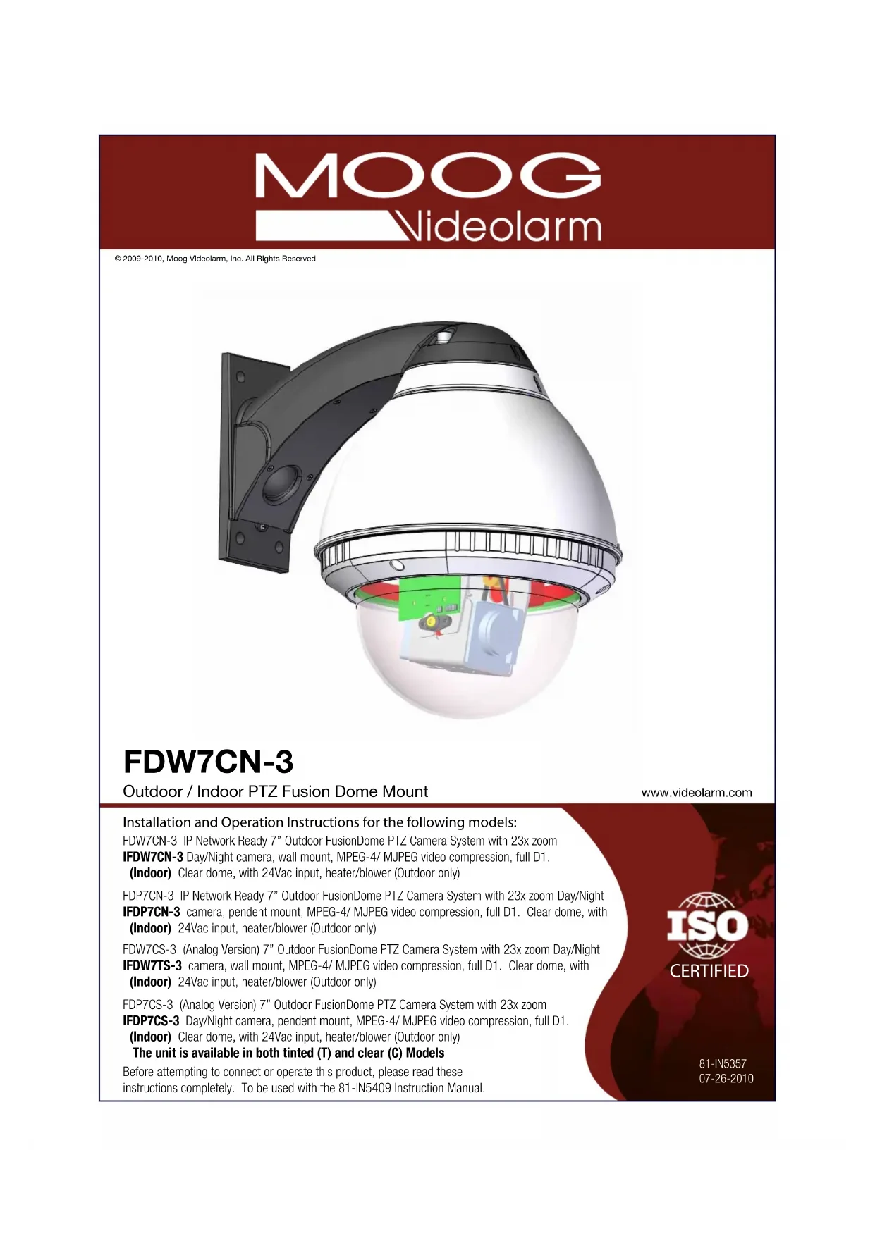
© 2009-2010, Moog Videolarm, Inc. All Rights Reserved
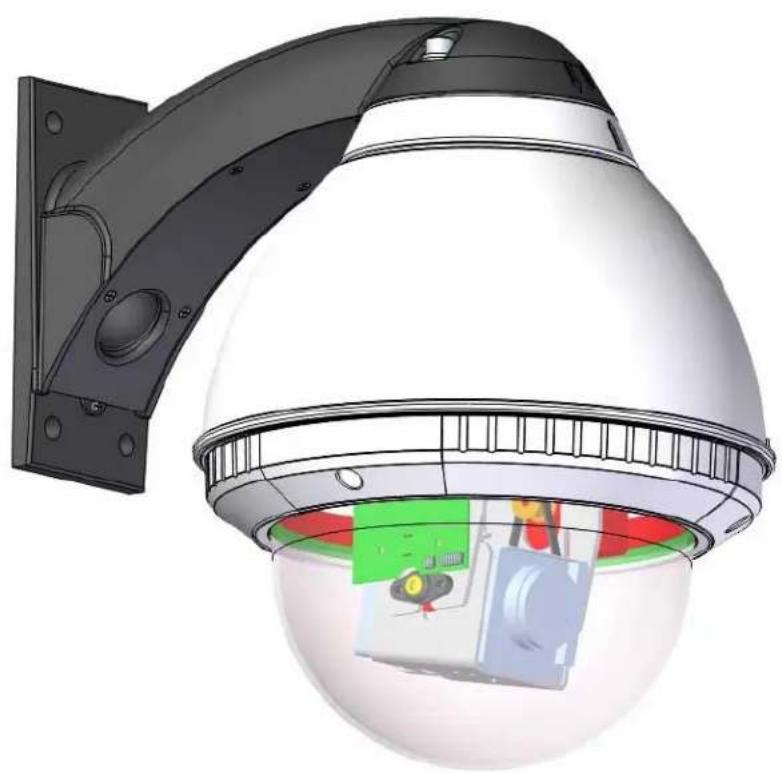
FDW7CN-3
Outdoor / Indoor PTZ Fusion Dome Mount
www.videolarm.com
Installation and Operation Instructions for the following models:
FDW7CN-3 IP Network Ready 7^ Outdoor FusionDome PTZ Camera System with 23x zoom
IFDW7CN-3 Day/Night camera, wall mount, MPEG-4/ MJPEG video compression, full D1. (Indoor) Clear dome, with 24Vac input, heater/blower (Outdoor only)
FDP7CN-3 IP Network Ready 7" Outdoor FusionDome PTZ Camera System with 23x zoom Day/Night
IFDP7CN-3 camera, pendent mount, MPEG-4/ MJPEG video compression, full D1. Clear dome, with (Indoor) 24Vac input, heater/blower (Outdoor only)
FDW7CS-3 (Analog Version) 7" Outdoor FusionDome PTZ Camera System with 23x zoom Day/Night
IFDW7TS-3 camera, wall mount, MPEG-4/ MJPEG video compression, full D1. Clear dome, with (Indoor) 24Vac input, heater/blower (Outdoor only)
FDP7CS-3 (Analog Version) 7" Outdoor FusionDome PTZ Camera System with 23x zoom
IFDP7CS-3 Day/Night camera, pendent mount, MPEG-4/ MJPEG video compression, full D1. (Indoor) Clear dome, with 24Vac input, heater/blower (Outdoor only)
The unit is available in both tinted (T) and clear (C) Models before attempting to connect or operate this product, please read these instructions completely. To be used with the 81-IN5409 Instruction Manual.

CERTIFIED
81-IN535707-26-2010
IMPORTANT SAFEGUARDS SAFETY PRECAUTI
1 Read these instructions.
2 Keep these instructions.
3 Heed all warnings
4 Follow all instructions.
5 Do not use this apparatus near water.
6 Clean only with damp cloth.
7 Do not block any of the ventilation openings. Install in accordance with the manufacturers instructions.
8 Cable Runs- All cable runs must be within permissible distance.
9 Mounting - This unit must be properly and securely mounted to a supporting structure capable of sustaining the weight of the unit.
Accordingly:
a. The installation should be made by a qualified installer.
b. The installation should be in compliance with local codes.
c. Care should be exercised to select suitable hardware to install the unit, taking into account both the composition of the mounting surface and the weight of the unit.
10 Do not install near any heat sources such as radiators, heat registers, stoves, or other apparatus (including amplifiers) that produce heat.
11 Do not defeat the safety purpose of the polarized or grounding-type plug. A polarized plug has two blades with one wider than the other. A grounding type plug has two blades and a third grounding prong. The wide blade or the third prong are provided for your safety. When the provided plug does not fit into your outlet, consult an electrician for replacement of the obsolete outlet.
12 Protect the power cord from being walked on or pinched particularly at plugs, convenience receptacles, and the point where they exit from the apparatus.
13 Only use attachment/ accessories specified by the manufacturer.
14 Use only with a cart, stand, tripod, bracket, or table specified by the manufacturer, or sold with the apparatus. When a cart is used, use caution when moving the cart/ apparatus combination to avoid injury from tip-over.
15 Unplug this apparatus during lighting storms or when unused for long periods of time.
16 Refer all servicing to qualified service personnel. Servicing is required when the apparatus has been damaged in any way, such as power-supply cord or plug is damaged, liquid has been spilled of objects have fallen into the apparatus, the apparatus has been exposed to rain or moisture, does not operate normally, or has been dropped.
Be sure to periodically examine the unit and the supporting structure to make sure that the integrity of the installation is intact. Failure to comply with the foregoing could result in the unit separating from the support structure and falling, with resultant damages or injury to anyone or anything struck by the falling unit.
UNPACKING
Unpack carefully. Electronic components can be damaged if improperly handled or dropped. If an item appears to have been damaged in shipment, replace it properly in its carton and notify the shipper.
Be sure to save:
1 The shipping carton and packaging material. They are the safest material in which to make future shipments of the equipment.
2 These Installation and Operating Instructions.
SERVICE
If technical support or service is needed, contact us at the following number:
TECHNICAL SUPPORT
AVAILABLE 24 HOURS
1-800-554-1124

The lightning flash with an arrowhead symbol, within an equilateral triangle, is intended to alert the user to the presence of non-insulated "dangerous voltage" within the product's enclosure that may be of sufficient magnitude to constitute a risk to persons.
The exclamation point within an equilateral triangle is intended to alert the user to presence of important operating and maintenance (servicing) instructions in the literature accompanying the appliance.
PRODUCTCATEGORY PARTS LABOR
All Enclosuresand Electronics Pan/Tilts
Poles/PoleEvators
Warrior/Q-View/I.R.llluminators
SView Series
Controllers
PowerSupplies
AccessoryBrackets
Five (5) Years
Three (3) Years **6 months if used in autoscan
Three (3) Years
Five (5) Years
Five (5) Years 6 months if used in autoscan
Five (5) Years /tour operation
Five (5) Years
Five (5) Years
Five (5) Years
Three (3) Years 6 months if used in autoscan
Three (3) Years /tour operation
Five (5) Years
Five (5) Years **6 months if used in autoscan
Five (5) Years /tour operation
Five (5) Years
Five (5) Years
During the labor warranty period, to repair the Product, Purchaser will either return the defective product, freight prepaid, or deliver it to Videolarm Inc. Decatur GA, The Product to be repaired is to be returned in either its original carton or a similar package affording an equal degree of protection with a RMA# (Return Materials Authorization number) displayed on the outer box or packingslip. To obtain a RMA# you must contact our Technical Support Team at 800.554.1124 extension 101. Videolarm will return the repaired Product freight prepaid to Purchaser. Videolarm is not obligated to provide Purchaser with a substitute unit during the warranty period or at any time. After the applicable warranty period, Purchasemust pay all labor and/or parts charges.
The limited warranty stated in these product instructions is subject to all of the following terms and conditions:
TERMS AND CONDITIONS
- NOTIFICATION OF CLAIMS: WARRANTY SERVICE: If Purchaser believes that the Product is defective in material or workmanship, then written notice with an explanation of the claim shall be given promptly by Purchaser to Videolarm but all claims for warranty service must be made within the warranty period. If after investigation Videolarm determines that the reported problem was not covered by the warranty, Purchaser shall pay Videolarm for the cost of investigating the problem at its then prevailing per incident billable rate. No repair or replacement of any Product or part thereof shall extend the warranty period as to the entire Product. The specific warranty on the repaired part only shall be in effect for a period of ninety (90) days following the repair or replacement of that part or the remaining period of the Product parts warranty, whichever is greater.
2.EXCLUSIVE REMEDY: ACCEPTANCE: Purchaser's exclusive remedy and Videolarm's sole obligation is to supply (or pay for) all labor necessary to repair any Product found to be defective within the warranty period and to supply, at no extra charge, new or rebuilt replacements for defective parts.
-
EXCEPTIONS TO LIMITED WARRANTY: Videolarm shall have no liability or obligation to Purchaser with respect to any Product requiring service during the warranty period which is subjected to any of the following: abuse, improper use: negligence, accident, lightning damage or other acts of God (i.e., hurricanes, earthquakes), modification, failure of the end-user to follow the directions outlined in the product instructions, failure of the end-user to follow the maintenance procedures recommended by the International Security Industry Organization, written in product instructions, or recommended in the service manual for the Product. Furthermore, Videolarm shall have no liability where a schedule is specified for regular replacement or maintenance or cleaning of certain parts (based on usage) and the end-user has failed to follow such schedule; attempted repair by non-qualified personnel; operation of the Product outside of the published environmental and electrical parameters, or if such Product's original identification (trademark, serial number) markings have been defaced, altered, or removed. Videolarm excludes from warranty coverage Products sold AS IS and/or WITH ALL FAULTS and excludes used Products which have not been sold by Videolarm to the Purchaser. All software and accompanying documentation furnished with, or as part of the Product is furnished "AS IS" (i.e., without any warranty of any kind), except where expressly provided otherwise in any documentation or license agreement furnished with the Product.
-
PROOF OF PURCHASE: The Purchaser's dated bill of sale must be retained as evidence of the date of purchase and to establish warranty eligibility.
DISCLAIMEROF WARRANTY
EXCEPT FOR THE FOREGOING WARRANTY, VIDEOLARM HEREBY DISCLAIMS AND EXCLUDING ALL OTHER WARRANTYES, EXPRESS OR IMPLIED, INCLUDING, BUT NOT LIMITED TO ANY AND/OR ALL IMPLIED WARRANTY OF MERCHANTABILITY, FITNESS FOR A PARTICULAR PURPOSE AND/OR ANY WARRANTY WITH REARGD TO ANY CLAM OF INFRINGEMENT THAT MAY BE PROVIDED IN SECTION 2-312(3) OF THE UNIFORM COMMERCIAL CODE AND/OR IN ANY OTHER COMPARABLE STATE STATUTE. VIDEOLARM HEREBY DISCLAIMS ANY REPRESENTATIONS OR WARRANTY THAT THE PRODUCT IS COMPATIBLE WITH ANY COMBINATION OF NON-VIDELARM PRODUCTS OR NON-VIDEOLARM RECOMMENDED PRODUCTS PURCHASER CHOoses TO CONNECT TO PRODUCT.
LIMITATION OF LIABILITY
THE LIABILITY OF VIDEOLARM, IF ANY, AND PURCHASER'S SOLE AND EXCLUSIVE REMEDY FOR DAMAGES FOR ANY CLAIM OF ANY KIND WHATSOEVER, REGARDLESS OF THE LEGAL THEORY AND WHETHER ARISING INTORT OR CONTRACT, SHALL NOT BE GREATER THAN THE ACTUAL PURCHASE PRICE OF THE PRODUCT WITH RESPECT TO WHICH SUCH CLAIM IS MADE. IN NO EVENT SHALL VIDEOLARM BE LIABLE TO PURCHASER FOR ANY SPECIAL, INDIRECT, INCIDENTAL, OR CONSEQUENTIAL DAMAGES OF ANY KIND INCLUDING, BUT NOT LIMITED TO, COMPENSATION, REIMBURSEMENT OR DAMAGES ON ACCOUNT OF THE LOSS OF PRESENT OR PROSPECTIVE PROFITS OR FOR ANY OTHER REASON WHATSOEVER.

Electrical Specifications
FDW7CN-3
FDW7CS-3
FDP7CN-3
FDP7CS-3
IFDW7CN-3
- IFDP7CN-3
Power 24VAC
Class 2 Only

80 Watts
Accessories: Heater: 50 Watts, Blower: 2 Watt Camera Power: (See Camera Specifications): 28 Watts Max Tools Required: 100^ Flat Head Screwdriver
English
24 VAC

Sorios: Calentador: 50 Watts, Blower: 2 VatoDe la Camara fotografica De : (Vease LasCaciones De la Camara fotografica): 28 Vatos
** Pan Tilt boxed separately along with its instructions.
- Pan/Tilt unit boxed separately
1
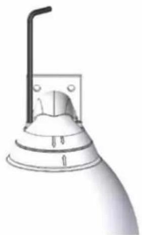
WALL MOUNTING
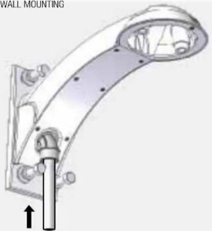
Bracket is designed for 45^ conduit fitting (If using the conduit). Run wire into bracket secure to wall.
- El soporte se dissea para la guarnacion del conducto 45^ (si usa el conductor). Funcione con el alambre en el soporte seguro para emparedar.
La parenthe est conque pour I'ajustage de precision du conduit 45^ (si a l'aide du conduit). Courez le fil dans la parenthe bloquee pour murer. - Haltewinkel ist für Befestigung des Rohres 45^ bestimmt (wenn das Rohr verwendet wird). Lassen Sie Draht in den Haltewinkel laufen, der, um zu ummauern sichere ist.
- O suporte é projetado para o encaixe da canalização 45^ (se usingo a canalização). Funcione o fio no suporte seguro para murar.
- La staffa è progettata per il montaggio del condotto 45^ (se per mezzo del condotto). Faccia funzionare il legare nella staffa sicura per murare.
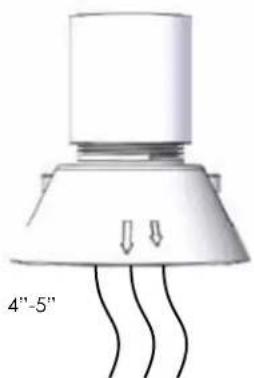
2
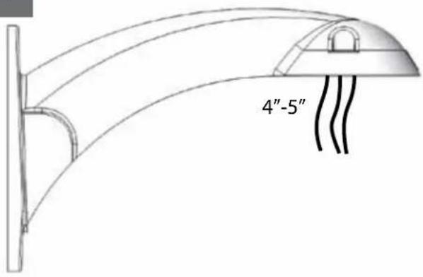
Trim incoming control & power wires to 4^ - 5^ for either wall or pendent bracket
- Con seguidad soporte del montaje a emparedar. Tire del cableado a trovés del soporte y del ajal de la posición según lo demostrado.
Solidement parenthese de bati a murer. Tirez le cablage par la parenthese et le canon isolant de positin comme montre, - Sicher Einfassung Haitewinkel wall. Ziehen Sie Verdrohtung durch Haitewinkel und Position Gummimuffe, wie gezeigt.
- Fimamente suporte da montagem a wall. Puxe a fiação atraves do suporte e dolhó da posicao como mestrado.
- Saldamente staffa del supporto da wall. Tiri i collegamenti tramite la staffa ed il gommino di prolezione di posizione come indicato.
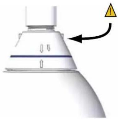
3
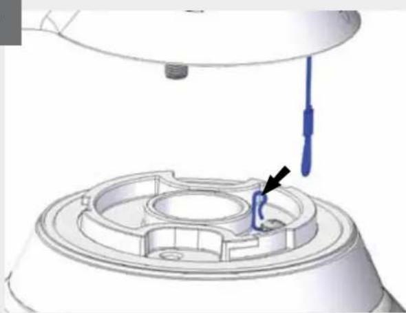
Secure lanyard to lanyard clip
- Can seguidad soporte del montaje a emparedar. Tire del cableado a trovés del soporte y del ojal de la posición según lo demostrado.
Solidement parenthese de bati a murer. Tirez le cablage par la parenthese et le canon isolant de position comme montré. - Sicher Einfassung Haltewinkel wall. Ziehen Sie Verdrahtung durch Haltewinkel und Position Gummimuffe, wie gezeigt.
- Fimamente suporte da montagem a wall. Puxe a fiação atraves do suporte e do IHó da posicao como muito.
Saldamente staffa del supporto da wall. Tir i collegamenti tramite la staffa ed il gommino di protezione di posizione come indicato.
4
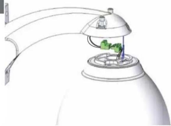
Complete ALL wiring connections
- Con seguidad soporte del montaje a emparedar. Tire del cableado a工程技术 del soporte y del ajal de la posicjion segun lo demostrado.
Solidement parenthese de bati a murer. Tirez le cablage par la parenthese et le canon isolant de position comme montré. - Sicher Einfassung Haltewinkel wall. Ziehen Sie Verdrohtung durch Haltewinkel und Position Gummimuffe, wie gezeigt.
- Fírmamente suporte da montagem a wall. Puxe a fiação atraves do suporte e dolhó da posicao como muito.
- Saldamente staffa del supporto da wall. Tiri i collegamenti framite la staffa ed il gommino di protezione di posizione come indicato.
5
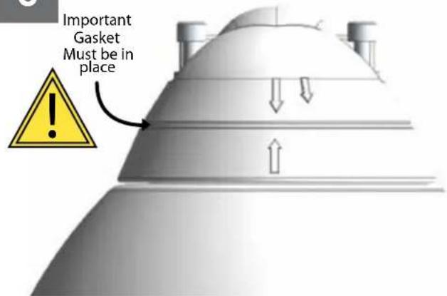
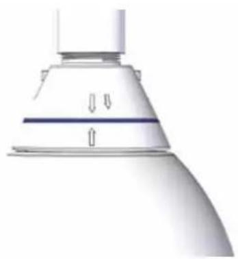
Align large arrows
- Con seguidad soporte del montaje a emparedar. Tire del cableado a trovés del soporte y del ajal de la posición según lo demostrado.
Solidement parenthese de bati a murer. Tirez le cablage par la parenthese et le canon isolant de position comme montré. - Sicher Einfassung Haftewinkel wall. Ziehen Sie Verdrohtung durch Haftewinkel und Position Gummimuffe, wie gezeigt.
Firmamente suporte da montagem a wall. Puxe a fiação atraves do suporte e dolhó da posicao como mestrado. - Saldamente staffa del supporto da wall. Tiri i collegamenti tramite la staffa ed il gommino di protezione di posizione come indicato.
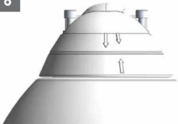
6
To lock turn clockwise
- Con seguidad soporte del montaje a emparedar. Tire del cableado a trovés del soporte y del ajal de la posición según lo demostrado.
Solidement parenthese de bati a murer. Tirez le cablage par la parenthese et le canon isolant de positio comme montré. - Sicher Einfassung Haitewinkel wall. Ziehen Sie Verdrohtung durch Haitewinkel und Position Gummimuffe, wie gezeigt.
- Fimamente suporte da montagem a wall. Puxe a falcao atraves do suporte e dolhó da posicao como mestrado.
- Saldamente staffa del supporto da wall. Tiri i collegamenti tramite la staffa ed il gommino di prolezione di posizione come indicato.
7
Secure with 14 " Allen wrench
- Can seguidad soporte del montaje a emparedar. Tire del cableado a través del soporte y del ajal de la posición según lo demostrado.
Solidement parenthese de bali a murer. Tirez le cablage par la parenthese et le canon isolant de position comme montré. - Sicher Einfassung Haltewinkel wall. Ziehen Sie Verdraughtung durch Haltewinkel und Position Gummimuffe, wie gezeigt.
Firmamente suporte da montagem a wall. Puxe a fiação atraves do suporte e do ilho da posicao como mestrado.
Saldamente staffa del supporto da wall. Tir i collegamenti tramite la staffa ed il gommino di protezione di posizione come indicato.
8
FOR PENDENT/WALL MOUNTING
Trim incoming control and power wires to 4-5 for either wall or pendent bracket
- La tapa segura de la cubierta SM5 con mercancías duras proportionsión; termine a la asamblea por las instrucciones SM5
Le dessus bloqué du logement SM5 avec les articles durs a fourni; accomplissez l'assemblée par instructions SM5 - Sichere Oberseite des Gehäuses SM5 mit den harten Waren bereitgestellt; schlieben Sie Versammlung pro Anweisungen SM5 ab
- Parte superior segura da carcaça SM5 com osmercadoriaduros fornecidos;termine o Conjunto por as instruções SM5
- Parte superiore sicura dell'alloggiamento SM5 con gli articoli duri forniti; completi l'assemblea per istruzioni SM5
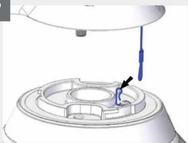
9
Secure lanyard to lanyard clip
- Con seguidad soporte del montaje a emparedar. Tire del cableado a través del soporte y del ajal de la posición según lo demostrado.
Solidement parenthese de bati a murer. tirez le cablage par la parenthese et le canon isolant de position comme montré. - Sicher Einfassung Haltewinkel wall. Ziehen Sie Verdrohtung durch Haltewinkel und Position Gummimuffe, wie gezeigt.
- Fírmamente suporte da montagem a wall. Puxe a fialação atraves do suporte e do llho da posicao como mestrado.
- Saldamente staffa del supporto da wall. Tiri i collegamenti tramite la staffa ed il gommino di prolezione di posizione come indicato.

10
Complete all wiring connections (coax wire not supplied)
- Termine todas las conexiones del cableado (alambre coaxil no suministrado)
- Accomplissez tous les raccordements de cablage (fil coaxial non foumi)
- Schlieben Sie alle Verdrahtungsanschlüsse ab (koaxialer Draht nicht geliefert)
- Termine todas as conexões da fiação (fio co-axial não fornecido)
- Completi tutti i collegamenti dei collegamenti (legare coassiale non fornito)
11
Align large arrows
To lock turn clockwise
Secure with 14 " Allen wrench
- Asegure con la llave Allen del 1/4"
Fixez cle Allen avec de 14
Sichern Sie mit 1 / 4 Inbusschlussel
Fixe com chave Allen do ¼ de"
Fissi con chiave di Allen del 14
14
To loosen - unscrew bolts 12 turn counter clockwise
- Paraifoldar-desatornillea la derecha contrario de la vuelta del 12 de los pernos"
Pour se desserrer - dans le sens des aiguilles d'une montre de tour dévissez de boulons 12 ) contre-
Um sich zu losen - schrauben Sie Schraubbolzen 1 / 2 Umdrehungs-Gegenrechtses herum ab - Para afrouxar - desaparafuse sentido horario contrario volta do 12 dos parafusos da"
Per allentare - sviti in senso orario di girata del 1/2 dei bulloni, contro
15
NETWORK:
| RJ45 | |||
| 24VAC | POWER | ||
| 1 | Camera | Red | Max 28 Watts |
| 2 | Camera | Orange | |
| 3 | Heater/Blower | Yellow | 52 Watts |
| 4 | Heater/Blower | Green | |
| 1/0 | |||
| 1 | Alarm 1 | Blue | |
| 2 | Alarm 2 | Violet | |
| 3 | Alarm 3 | Gray | |
| 4 | Common | White | |
| BNC (Not Used with NETWORK) | |||
ANALOG:
| 24VAC | POWER | ||
| 1 | Camera | Red | Max 28 Watts |
| 2 | Camera | Orange | |
| 3 | Heater/Blower | Yellow | 52 Watts |
| 4 | Heater/Blower | Green | |
| 1/0 | |||
| 1 | RS-485RX A | Blue | |
| 2 | RS-485RX B | Violet | |
| 3 | RS-485TX A | Gray | |
| 4 | RS-485TX B | White | |
| BNC | |||
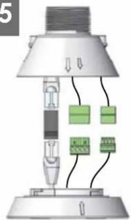
Make the appropriate male and female connections. Indoor model does not include pre-run cables.
Haga las conexiones masculinas y femininas apropiadas. El modelo de inferior no incluye pre-functiona los cables.
- Etablissez les rapport masculins et femelles appropriés. Le modele d'intérieur n'inclut pas pré-courent des cables.
- Stellen Sie die passenden mönlichen und weiblichen Beziehungen her. Innenmodell schlieBt nicht vor-laufen halten Kabel ein.
- Faça as conexões masculinas e fêmeas apropriadas. O Modelo indoor não inclui pre-funciona cabos.
Faccia i collegamenti maschii e femminili adatti. Il modello dell'interno non include pre-fa funzionare i cavi.
16
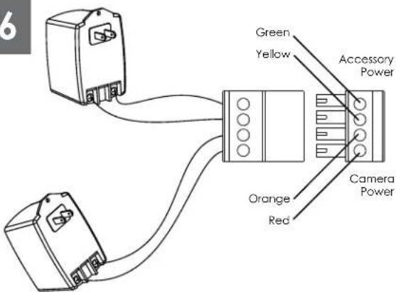
Camera = red & orange wires to terminal Heater/Blower = yellow & green wires to terminal
- Camara fotografica = alambre rojos y anaranjados al terminal Heater/Blower = alambre del amarillo y del verde al terminal
Appareil-photo = fils rouges et oranges à la borne Heater/Blower = fils de jaune et de vert à la borne - Kamera = rote u. orange Leitungen zum Anschluß
- Heater/Blower = Gelb- u. Grünleitungen zum Anschluß
- Camera = fios vermelhos & alaranjados ao terminal
Heater/Blower = fios do amarelo & do verde ao tem
Macchina fotografica = legareRossi & arancioni al terminale Heater/Blower = legare di verde & di colore giallo al terminale
12
Wire Gauge
| Total vA consumed | ,5 | ,75 | 1,0 | 1,5 | 2,5 | 4 | 6 | MM2AWG |
| 22 | 20 | 18 | 16 | 14 | 12 | 10 | ||
| 5.5 | ft m | 400 | 600 | 960 | - | - | - | |
| 10 | 120 | 180 | 300 | 480 | 800 | 1300 | - | |
| 36.5 | 54.9 | 91.4 | 146 | 243 | 396 | - | ||
| 20 | 89 | 141 | 225 | 358 | 571 | 905 | 1440 | |
| 27.1 | 43.0 | 68.6 | 109 | 174 | 275 | 438 | ||
| 30 | 65 | 90 | 130 | 225 | 350 | 525 | 830 | |
| 19.8 | 27.4 | 39.6 | 68.6 | 106 | 160 | 252 | ||
| 40 | 44 | 70 | 112 | 179 | 285 | 452 | 720 | |
| 13.4 | 21.3 | 34.1 | 54.6 | 86.9 | 138 | 219 | ||
| 50 | 35 | 56 | 90 | 143 | 228 | 362 | 576 | |
| 10.6 | 17.1 | 27.4 | 43.6 | 69.5 | 110 | 175 | ||
| 60 | 29 | 47 | 75 | 119 | 190 | 301 | 480 | |
| 9.4 | 14.3 | 22.9 | 36.2 | 57.9 | 91.7 | 146 | ||
| 70 | 25 | 40 | 64 | 102 | 163 | 258 | 411 | |
| 8.8 | 12.2 | 19.5 | 31.1 | 49.7 | 78.6 | 125 | ||
| 80 | 31 | 34 | 55 | 85 | 140 | 215 | 340 | |
| 7.6 | 10.3 | 16.8 | 25.9 | 42.7 | 65.5 | 103 |
These are recommended maximum distances for 24VAC with a 10% voltage drop.
- Estos se recomienda las distancias的最大as para 24VAC con una goto del voltage del 10% .
- Ceux-ci sont recommandes des distances maximum pour 24VAC avec une chute de tension de 10% .
- These werden maximale Abstände für 24VAC mit einem 10% Spannungsabfall empfohlen.
- Estes são recomendados distancias Tmaxas para 24VAC com uma queda de tensao de 10% .
- Questi sono suggeriti distance massime per 24VAC con una differenza de potenziale di 10% .
18
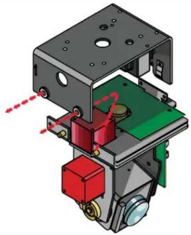
Remove Pan/Tilt from shipping carton. Install in base bracket in housing.
- Quite Pan/Tilt del cartón del envío. Instale en soporte bajo en la cubierta.
- Enlevez Pan/Tilt du carton d'expédition. Installez dans la parenthèse basse dans le logement.
- Entfernen Sie Pan/Tilt vom Verschiffenkarton. Bringen Sie in niedrigen Halfewinkel im Gehäuse an.
- Remova Pan/Tilt da caixa do transporte. Instale no suporte baixo na carcaça.
- Rimuova Pan/Tilt alla scatola di trasporto. Installi in staffa bassa in alloggiamento.
19
CAPTIVE SCREW
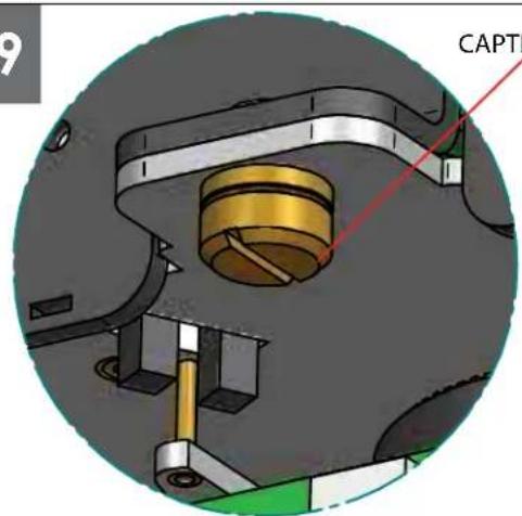
To secure in place, tighten captive screw.
- Para asegurar en lugar, apriete el tornillo prisonero.
- Pour fixer en place, serrez la vis captive.
- Um im Platz zu sichern,ziehen Sie Sicherheitsschraube fest.
- Para fixar-se no lugar, aperte o parafuso prisioneiro.
Per fissare sul posto, stringa la vite prigioniera.
20
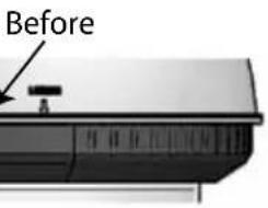
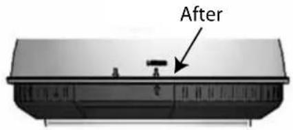
Align the arrows on the outside of the dome and lock.
Fasten down the dome with a Phillips screwdriver.
- Sujete abajo de la boVEDa con un destornillador Phillips.
- Attachez en bas du dôme avec un tournevis Phillips.
- Befestigen Sie sich hinunter die Haube mit einem Kreuzkopfschraubenzieher.
- Prenda abaixo a abóbada com uma chave de fenda Phillips.
Fissisi giu la cupola con un cacciavite "phillips".
22
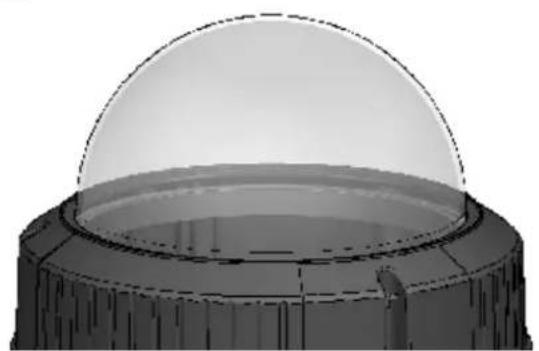
Wipe the dome clean.
- Limpie la bóveda limpia.
- Essuyez le dôme.
- Wischen Sie die Haube sauber ab.
- Limpe a abóbada limpa.
- Asciughla cupola.
23
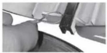
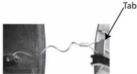
Loop the lanyard around the tab inside the housing.
- Coloque el acollador alrededor de la lengüeta bajo el centro del cierto.
- Faites une boucle la lanière autour de l'étiquette à l'intérieur du logement.
- Schlingen Sie die Abzuglinie um den Vorsprung innerhalb des Gehäuses.
- Dé lacos no colhedor em torno da aba dentro da carcaça.
- Colleghi la cordicella in circuito intorno alla linguetta all'interno dell'alloggiamento.
PB24 Addendum
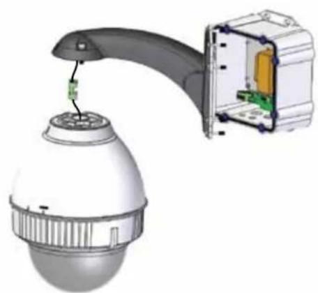
Additional wires are provided to run power to PB24. Use with connector supplied. Run RJ45 connector through PB24, wall mount, and connect lead from housing.
- Los alambre s adcionales se proporcionan a la energia funcionada con a PB24. El uso con el connectador proveyo. Funcione con el connectador RJ45 con PB24, emparede el montaje, y connecte el plomo de la cubierta.
Des fil additionnels sont fournis à la puissance courue à PB24. L'utilisation avec le connecteur a fourni. Courez le connecteur RJ45 par PB24, murez le bati, et reliez le fil du logement. - Zusätzliche Drähte zur Verflügung gestellt zu laufen gelassener Energie zu PB24. Gebrauch mit Verbindungsstücklieferte. Laufen lassen Sie Verbindungsstuck RJ45 durch PB24, ummaern Sie Einfassung und anschließen Sie Blei vom Gehäuse n.
Os fios adcionais sao fornecidos ao poder funcaoado a PB24. O uso com conector forneceu. Funcione o conector RJ45 com PB24, mure a montagem, e connecte a ligaao da carcaça. - I legare supplementari sono forniti a potere funzionato a PB24. L'uso con il connettore ha fornito. Faccia funzionare il connettore RJ45 con PB24, muri il supporto e colleghi il cavo da alloggiamento.
Replacement Parts List
FDW7CN-3
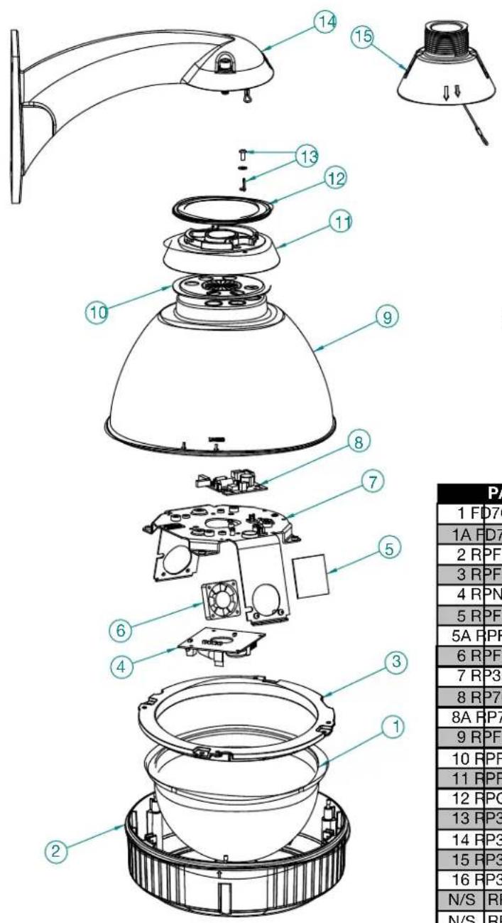
PART NUMBER DESCRIPTION
| 1 FD7C CLEAR REPLACEMENT CAPSULE |
| 1A FD7T TINTED REPLACEMENT CAPSULE |
| 2 RPFD7501 LOWER TRIM RING |
| 3 RPFD703 DOME CLAMPING RING |
| 4 RPNET02 NETWORK HGS POWER SUPPLY |
| 5 RPFD072 24V HEATER |
| 5A RPFD072/12 12V HEATER (12VDC MODELS ONLY) |
| 6 RPFD080 BLOWER |
| 7 RP3510 CAMERA BRACKET |
| 8 RP70FP7PB CONNECTION PCB(24VAC) |
| 8A RP70FP7PB12 CONNECTION PCB (12VDC) |
| 9 RPFD040 HOUSING TOP |
| 10 RPFD2612 HOUSING TOP GASKET |
| 11 RPFD3245 WALL/PENDE NT ADAPTER |
| 12 RPGK3356 WALL/PENDENT GASKET |
| 13 RP3458 LANYARD SET |
| 14 RP3551 WM11 WALL MOUNT |
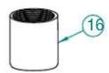
| 15 RP3606 PENDENT MOJNT BRACKET |
| 16 RP3719 1 1/2 FEMALE /FEMALE COUPLING |
| N/S RPPKH2098 BRACKET PACKET ASSEMBLY |
| N/S RPPKE1100 ELECTRICAL PACKET ASSEMBLY |
| N/S RPTRAN02 110 TO 24VAC WALL TRANSFORMER |
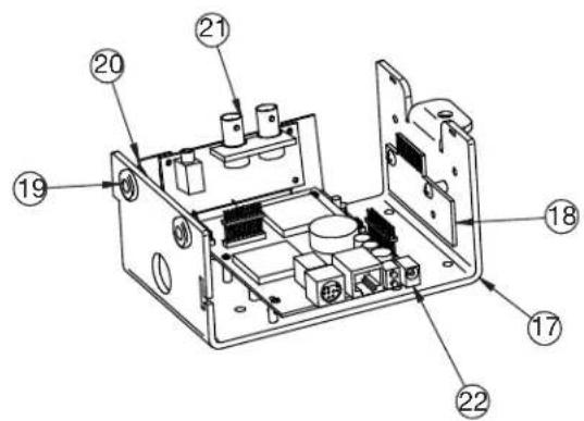
| 17 RPVL2857 PAN/TILT BASE BRACKET |
| 18 RP76VL385A PAN/TILT CONNECTION PCB |
| 19 RP96PSGK08 PANT/TILT GROMMET |
| 20 RPVL3097 IP CARD BRACKET |
| 21 RP76P0F060E IP CONNECTION PCB |
| 22 RP7OP14015 IP CARD |
Product Registration/Warranty
Thank you for choosing Videolarm. We value your patronage and are solely committed to providing you with only the highest quality products available with unmatched customer service levels that are second-to-none in the security industry.
Should a problem arise, rest assure that Videolarm stands behind its products by offering some of the most impressive warranty plans available: 3 Years on all Housings, Poles, Power Supplies, and Accessories and 5 Years on all camera systems (SView, QView, Warriors), and InfraRed Illuminators.
Register Your Products
Option 1: Online Option 2: Mail-In
Take a few moments and validate your purchase with our Online Product Registration Form at www.videolarm.com/productregistration.jsp
or complete and mail-in the bottom portion of this flyer.
Register your recent Videolarm purchases and benefit from the following:
- Simple and Trouble-Free RMA process
- Added into customer database to receive product updates / news
- Eliminate the need to archive original purchase documents:
Receipts, Purchase Orders, etc...
Place in envelope, affix stamp and mail to:
Cut at the dotted Line
Main Contact Info
Videolarm ATTN: Warranty
2525 Park Central Ave.
Decatur, GA 30035
First Name: Last Name:
Professional Title: Company:
Address 1: Address 2:
City: State / Province/Country:
Zip / Postal Code: Phone Number: E-mail Address:
Product Information
Please Circle One: Business
Personal
Name & Location of Company / Store where Purchased:
(City, State, Country)
Videoalarm Product ID Product Description
Serial #
(Available only for Camera Systems, IR Illuminators, Wireless Devices)
PO#