WS1C-50NF-X2 - Surveillance Camera Moog Videolarm - Free user manual and instructions
Find the device manual for free WS1C-50NF-X2 Moog Videolarm in PDF.

User questions about WS1C-50NF-X2 Moog Videolarm
0 question about this device. Answer the ones you know or ask your own.
Ask a new question about this device
Download the instructions for your Surveillance Camera in PDF format for free! Find your manual WS1C-50NF-X2 - Moog Videolarm and take your electronic device back in hand. On this page are published all the documents necessary for the use of your device. WS1C-50NF-X2 by Moog Videolarm.
USER MANUAL WS1C-50NF-X2 Moog Videolarm
PRODUCT INSTRUCTIONS
TABLE OF CONTENTS
Cable and Power Guidelines 1, 12
Installation Preparation 1
Installation Procedure 1
Wiring 2
Optional Warrior Test Monitor Cable 2
Camera Bracket Setup 2
Camera Focusing 3
Camera Settings 3
Completion of Installation 5
Dome/Window Care 5
NVT Instructions 6
IFS Instructions 7
Warranty Information 8
Service and Safeguard Information 9
Troubleshooting 10
Exploded View WS1 13
Replacement Parts List WS1 14
Exploded View WS3 15
Replacement Parts List WS3 16
natural_image
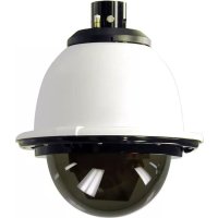
Close-up of hands holding a small electronic device (no visible text or symbols)Figure 1
INSTALLATION PROCEDURE
- Using the security tool provided, loosen the four security fasteners and remove the housing top. NOTE: The housing top is held to the base by a lanyard.
- Determine which side the conduit outlet will be located on: Top, bottom, left, or right.
NOTE: In protected outdoor applications place the conduit outlet in the bottom position, facing the ground.
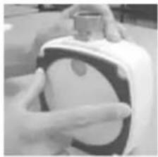
- Position the housing in the desired location and mark the four mounting holes (Figure 2).
CABLE AND POWER GUIDELINES
(Detailed info on Page 12)
This chart shows the proper current needed for power supplies for Warrior Series cameras. Use Class 2 Power only. Input voltage must be between 12-28 VDC or 15-28 VAC.
| VOLTAGE | CURRENT | POWER |
| 12 VDC | 350mA | 4.2W |
| 24 VAC | 202mA | 4.8W |
Depending on the voltage being used, refer to one of the formulas below to select the correct power supply for cameras connected in parallel (positive to positive, negative to negative):
Total current for a 12 VDC system:
TOTAL CURRENT = (350mA x total number of cameras)
Total current for a 24 VAC system:
TOTAL CURRENT = (202mA x total number of cameras)
Mounting Holes
natural_image
Interior view of an electronic device showing internal components and wiring (no visible text or symbols)Set screw
Conduit outlet (Place on bottom in protected outdoor applications)
Figure 2
- Pull video and power wires through the desired conduit access hole. Use the correct conduit plug to cover the unused hole.
NOTE: For outdoor applications use Teflon™ tape on the threads.
A. Use the 1/2" conduit plug to cover the 1/2" threaded hole. Attach using a flat head screwdriver.
B. Use the 3/4" conduit plug to cover the 3/4"
threaded
hole. To do this loosen the 6-32 set screw that holds the connector in, remove the connector and replace it with the plug. Once the plug is tightened down, retighten the set screw.
NOTE: Make sure that the conduit plug and set screw are securely tightened to help prevent tampering.
- Attach the housing using #10 mounting screws, placing the provided mounting pads against the head of the screw.
NOTE: When installing outdoors, remember to use sealant around the screws and the back of the housing.
WIRING (Figure 3)

Use Class 2 Power only. Input voltage must be between 12-28 VDC or 15-28 VAC.
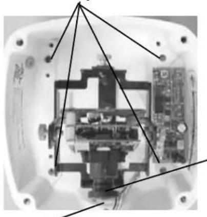
- Connect the output of your Class 2 Power Supply to the terminal connectors on the PC Board inside the housing. Refer to the Troubleshooting section later in this instruction sheet for more information.
- Connect the incoming video cable to the BNC connector.
NOTE: For NVT Twisted Pair see Addendum 1, for IFS Fiber see Addendum 2.
text_image
Terminal Connector Power Board Positive Connected to the Camera Negative Connect to incoming video BNCFigure 3
OPTIONAL WARRIOR TEST MONITOR CABLE (Part # - WSTMC)
DESCRIPTION
The Warrior Test Monitor Cable is a tool that allows users to view video from cameras via a small on-site monitor. It's quick and easy to use.
- Using the security tool provided, loosen the four security fasteners and remove the housing top. NOTE: The housing top is held to the base by a lanyard.
- Locate the power board on the inside of the housing. The Test Monitor Cable plug is located beside the terminal block where incoming power is connected (Figure 4).
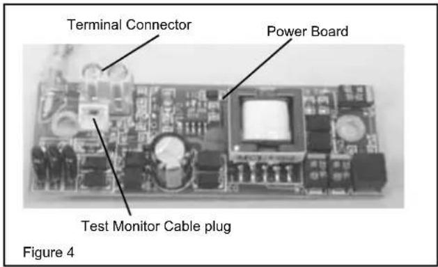
text_image
Terminal Connector Power Board Test Monitor Cable plug Figure 4- Plug the test monitor cable into the power board (Figure 5). Attach the BNC connector to your test monitor.
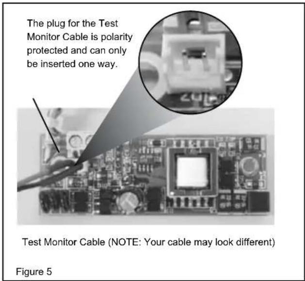
text_image
The plug for the Test Monitor Cable is polarity protected and can only be inserted one way. Test Monitor Cable (NOTE: Your cable may look different) Figure 5NOTE: The following instructions are for camera bracket setup, camera focusing, and camera set-up. The final steps for installation follow these sections.
CAMERA BRACKET SETUP
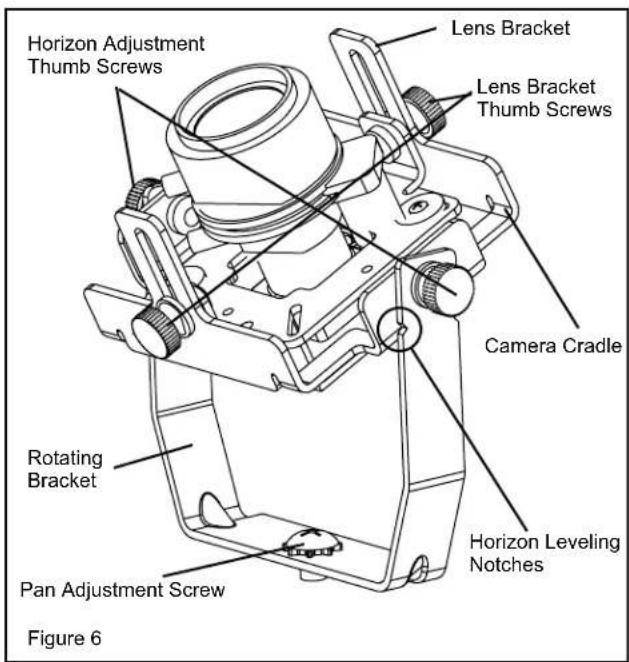
Once the housing is installed, the three axis camera bracket allows the camera to be adjusted to the desired viewing location and angle (Figure 6, next page).
IMPORTANT: A sticker has been placed on top of the lens holder of the camera to help in orienting the unit correctly.
text_image
Horizon Adjustment Thumb Screws Lens Bracket Lens Bracket Thumb Screws Camera Cradle Rotating Bracket Pan Adjustment Screw Figure 6 Horizon Leveling NotchesBracket Alignment:
Wall mount: Be sure the rotating bracket is positioned vertically. Ceiling mount: Be sure the rotating bracket is aligned to point toward the desired viewing location.
- Adjust the Pan: Loosen the two Camera Cradle thumb screws and turn the camera lens to face toward the side of the housing. Use a Phillips head screwdriver to loosen the screw holding the rotating bracket in place. Adjust the bracket and retighten the screw to lock the bracket in place.
- Adjust the Horizon: The camera must be parallel to the ground. To adjust the horizon, loosen the two thumb screws on the Camera Cradle and tilt as needed. Notches are included on the rotating bracket to help determine if the cradle is level. Retighten the thumb screws.
- Adjust the Tilt: Loosen the two thumb screws on the Lens Bracket and tilt the camera/lens to the desired location. The lens can also be adjusted up and down if needed. Retighten the thumb screws.
NOTE: Use Loctite™ or an equivalent product to secure the thumb screws, especially where vibration is a concern.
cAMErA FocusInG
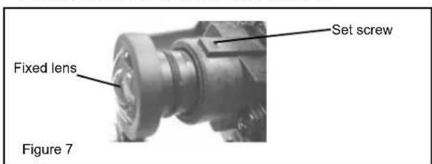
Fixed Lens: Loosen the set screw in the lens mount and to manually rotate the lens until a clear picture is achieved. Once the focus is set, retighten the set screw (Figure 7).
text_image
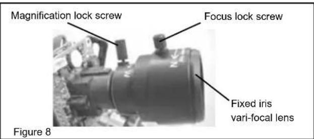
Set screw Fixed lens Figure 7Vari-Focal Lens: First, adjust the Magnification Lock Screw to the desired magnification (telephoto to wide angle). Tighten the Lock Screw. Next, adjust the Focus Lock Screw until a clear picture is achieved. Tighten the Lock Screw (Figure 8).
text_image
Magnification lock screw Focus lock screw Fixed iris vari-focal lens Figure 8Auto Iris Lens:
notE: tHE Auto Irls LEns Is sEt At tHE FActorY.
- IF You EXPErlEncE VldEo too LIGHT or dArK Auto Irls AdJustMEnt MAY BE nEEdEd.
sEE tHE trouBLEsHootInG sEctlon For AdJustMEnt InForMATlon.
cAMErA sEttInGs
notE: To determine which camera is used in your unit, locate the serial number on the inside of the housing. Match the two letter prefix with the corresponding instructions included here for adjustments.
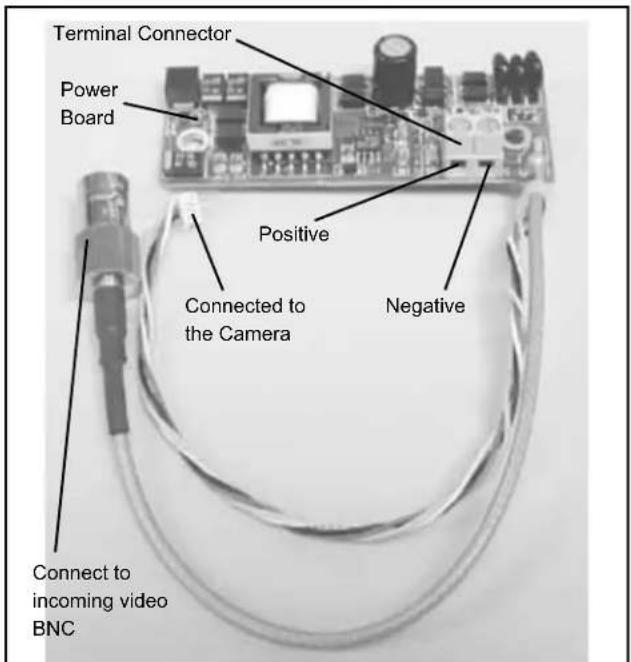
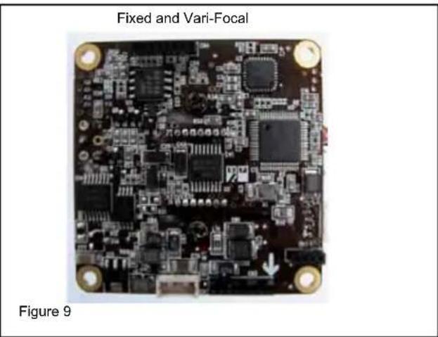
FIXED AND FIXED VARI-FOCAL LENSES. There are no user adjustable settings on these units (Figure 9).
natural_image
Close-up of a fixed and vari-focal integrated circuit board (PCB) with visible components and mounting holes, labeled as Figure 9 (no text or symbols on the circuit itself)COMPLETION OF INSTALLATION
- A cardboard template is included to test the adjustment of your lens/bracket setup before reattaching the housing top. Place the template over the lens/bracket set up, either on the back of the housing or in opposing front plate screw holes depending on the orientation of the setup. If the lens touches the cardboard the setup WILL touch the dome or window. Readjust accordingly.
- When the desired focus and location are achieved tighten the thumb screws on the brackets in place using needle-nose pliers. Use Loctite™ or an equivalent product to secure the screws, especially in installations where vibration is a concern.
- WARRIOR 1 - Adjust the inner liner so that the camera lens "sees" through the opening. Replace the housing top and tightly fasten the (4) security screws with the security tool. WARRIOR 3 - Replace the housing top and tightly fasten the (4) security screws with the security tool.
DOME/WINDOW CARE
WARRIOR 1
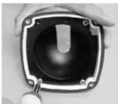
Handle the dome carefully to prevent scratching. If a scratch appears over the lens you can turn the dome to move the scratch out of view. Remove the housing top as noted earlier. Loosen the (4) 10-32 Phillips head screws inside the top and turn the dome to the desired orientation (Figure 17). Retighten the screws and replace the top, making sure the inner liner opening lines up with the camera lens. Clean the dome with an appropriate non-abrasive cleaner.
natural_image
Close-up of hands holding a black square speaker with a central knob, no visible text or symbolsFigure 17
WARRIOR 3
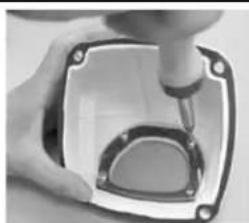
The Warrior 3 is equipped with a scratch resistant window and a Window Guard™ paint shield. The shield can be quickly changed in cases of vandalism. Remove the housing top as directed earlier. Loosen the (4) 8-32 Phillips head screws holding the window in place and take out the window (Figure 18). Remove the vandalized paint shield and replace it with a new one. Reattach the window, making sure the paint shield is between the housing and the window, and reattach the housing top. Clean the window with an appropriate non-abrasive cleaner.
natural_image
Close-up of a hand using a tool to apply a component into a circular opening (no visible text or symbols)Figure 18
ADDENDUM 1
UNSHIELDED TWISTED PAIR VIDEO WIRING

NOTE: The customer must purchase the Video Transceiver from NVT. Part numbers are:
• NV-212A (500 ft.)
* NV-213A or NV-213A-M (1000 ft.)
• NV-652R, NV-862R, or NV-1662R (3000 ft.)
The cameras included in the Warrior series are able to transmit video signals to NVT receivers via unshielded twisted pair cable. You must purchase the receiver separately. Instructions for connecting the receiver end of the unshielded twisted pair cable will be included with the NVT receiver. Following are instructions for connecting the unshielded twisted pair cable to the PC board inside your Warrior housing. See the TROUBLESHOOTING section in the back of these instructions if you experience any problems.
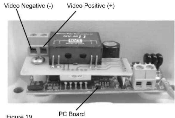
- Connect the unshielded twisted pair cable to the positive and negative screw terminals on the Warrior PC board (Figure 19).
text_image
Video Negative (-) Video Positive (+) NV-M11 RVAS Figure 19 PC BoardFigure 19
- Connect the other end of the unshielded twisted pair cable to the NVT receiver.
CAUTION: The unshielded twisted pair video signal is polarity dependent. The positive video terminal on the Warrior PC board MUST be connected to the positive terminal on the NVT receiver, and negative MUST be connected to negative.
- When using unshielded twisted pair cable you DO NOT need the BNC connector. Be sure that there is no video connection other than the unshielded twisted pair cable.
Wiring Notes
Wire — What to DO
- DO use point-to-point Unshielded Twisted Pair wire, gauge 24 or thicker, stranded or solid, Category 2, 3, 4, or 5.
- The video signal may co-exist in the same wire bundle as other video, telephone, data, control signals, or low-voltage power. It is also OK to run NVT video signals in or near electromagnetic fields (in accordance with National Electrical Code, local, or other local safety requirements).
- DO measure the wire distance. Use only transceivers that are designed for that distance.
- DO make sure the pair of wires carrying the video signal is sent as a twisted pair (e.g. the blue-white/white-blue wires twisted together as a pair), not a "split-pair" (e.g. blue-white conductor, part of one pair/orange-white conductor, part of another pair).
Wire — What NOT to DO
- DO NOT USE SHIELDED TWISTED PAIR WIRE. It will severely degrade the distance performance. Short runs may be used with some signal degradation (for example elevator traveler cables). Multi-pair wire with an overall shield is OK.
- DO NOT USE UN-TWISTED WIRE. It will reduce the NVT product's inherent interference immunity.
- DO NOT allow your installation to have "bridge-taps", loading coils, talk-battery, or MOV type protectors. Bridge-taps are where a twisted pair is connected to two twisted pairs (such as an extension phone at home). Bridge-taps cause reflections as the signal propagates, resulting in "ghosts" in the video image, and are to be avoided.
- If the phone company is providing the cable runs between buildings, make sure it's "dry copper" i.e. it should have none of the following: dial-tone, 48 volts, loading coils, bridge-taps, switching, or long paths to the phone company's central office and back.
- Due to near-end crosstalk, DO NOT send a transmit and a receive signal in the same wire bundle. Exceptions: Less than 1,000 ft (300m), or Category 5 cable, up to 2,000 ft (600m) are OK.
- DO NOT send "Up-the-Coax" Pan/Tilt/Zoom signals through active (amplified) NVT transceivers.

- For safety, never put NVT signals in the same conduit as high-voltage wiring.

- WARNING — to reduce a risk of fire or electrical shock, do not expose this product to rain or moisture.
Measure your wire distance
Note: All NVT quoted distance specifications include any coax in the run. It is recommended that the wire distance be measured to ensure that the capability of the NVT product is correct.
Wire resistance may be measured with an ohm-meter by shorting the two conductors together at the far end, and measuring the loop-resistance out and back. Compare your readings with the charts on the next page.
| Distance | Unshielded Twisted Pin Wt & Gauge (Wt) | ||||
| 18 | 19 | 20 | 22 | 24 | |
| 250 ft | 5 8 | 13 W | W | W | |
| 300 ft | 6 10 | 16 W | W | W | |
| 400 ft | 5 6 | 8 13 W | 21 W | W | |
| 500 ft | 6 8 | 10 16 W | 26 W | W | |
| 600 ft | 8 10 | 12 19 W | 31 W | W | W |
| 800 ft | 10 13 | 16 25 W | 42 W | W | |
| 1000 ft | 13 16 | 20 22 W | 52 W | W | |
| 1250 ft | 16 20 | 25 30 W | 65 W | W | |
| 1500 ft | 24 30 | 48 78 W | W | W | |
| 1750 ft | 23 28 | 35 65 W | 91 W | W | W |
| 2000 ft | 32 40 | 63 104 W | W | W | |
| 2500 ft | 40 49 | 79 131 W | W | W | |
| 3000 ft | 48 59 | 95 157 W | W | W | |
| 3500 ft | 56 69 | 111 183 W | W | W | |
| 4000 ft | 64 79 | 127 209 W | W | W | |
| 5000 ft | 80 99 | 158 269 W | W | W | |
| 6000 ft | 78 95 | 119 190 W | 313 W | W | W |
| 8000 ft | 104 127 | 158 253 W | 418 W | W | W |
| Cable Distance | Unshielded Twistless Paint Ww & Gager A (Wt) | ||||
| 18 | 19 | 20 | 22 | 24 | |
| 75 m | 3 | 4 | 5 | 6 | 7 |
| 100 m | 4 | 5 | 6 | 7 | 8 |
| 125 m | 5 | 6 | 7 | 8 | 9 |
| 150 m | 6 | 7 | 8 | 9 | 10 |
| 200 m | 9 | 10 | 11 | 12 | 13 |
| 300 m | 13 | 14 | 15 | 16 | 17 |
| 400 m | 17 | 18 | 19 | 20 | 21 |
| 500 m | 21 | 22 | 23 | 24 | 25 |
| 600 m | 26 | 27 | 28 | 29 | 30 |
| 750 m | 32 | 33 | 34 | 35 | 36 |
| 900 m | 38 | 39 | 40 | 41 | 42 |
| 1000 m | 43 | 44 | 45 | 46 | 47 |
| 1200 m | 51 | 52 | 53 | 54 | 55 |
| 1500 m | 64 | 65 | 66 | 67 | 68 |
| 1800 m | 77 | 78 | 79 | 80 | 81 |
| 2400 m | 102 | 103 | 104 | 105 | 106 |
| Cable Distance | Unshielded Twisted Ball Wire Days in (m) | ||||
| 1.08 | 0.88 | 0.78 | 0.68 | 0.580.68 | |
| 75 m B | 3 5 6 6 9 13 W | ||||
| 100 m B | 4 7 9 12 18 W | ||||
| 125 m B | 6 8 11 15 22 W | ||||
| 150 m B | 7 10 13 18 27 W | ||||
| 200 m B | 9 13 17 24 36 W | W | |||
| 300 m B | 13 20 26 36 54 W | ||||
| 400 m B | 18 27 35 48 72 W | ||||
| 500 m B | 22 33 43 60 90 W | ||||
| 600 m B | 26 40 52 72 108 W | ||||
| 750 m B | 33 50 65 89 135 W | ||||
| 900 m B | 40 60 78 107 162 W | ||||
| 1000 m B | 44 66 86 119 179 W | ||||
| 1200 m B | 53 80 104 143 215 W | ||||
| 1500 m B | 66 100 130 179 269 W | ||||
| 1800 m B | 79 120 155 215 323 W | ||||
| 2400 m B | 106 159 207 286 431 W | ||||
AddEnduM 2
IFS FIBER CONNECTION

notE: The customer must purchase the Receiver from IFS. Part number are:
• VR1000
• VR1001
- VR1001-R3
• VR1100
- VR1100-R3
• VR2100
- VR2100-R3
Lifetime warranty on the fiber module
- Connect power to the terminal connector as shown in the general instructions.
- Select a quality fiber optic cable containing either 50/125 or 62.5/125 fiber. Attach an ST style fiber optic connector to the cable using the connector manufacturer's recommended procedures.
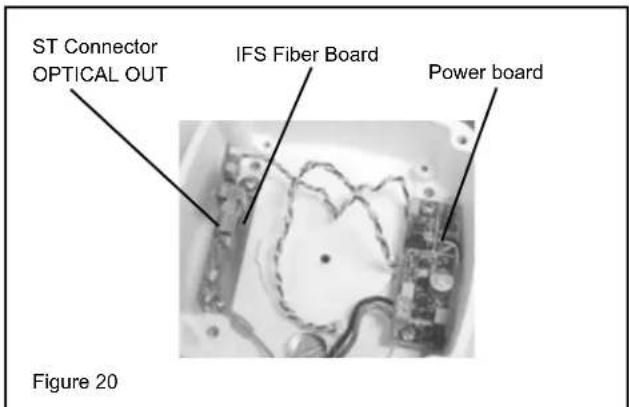
- Attach the connector just assembled to the ST Connector OPTICAL OUT. Feed the cable through the conduit opening. Complete connections and attach outside the housing according to manufacturer's recommended procedures.
text_image
ST Connector OPTICAL OUT IFS Fiber Board Power board Figure 20TROUBLESHOOTING
If you experience problems with the camera picture please check these simple troubleshooting procedures for possible solutions before calling technical support.
STATIONARY OR SCROLLING HORIZONTAL LINES ON SCREEN
GROUND LOOPS
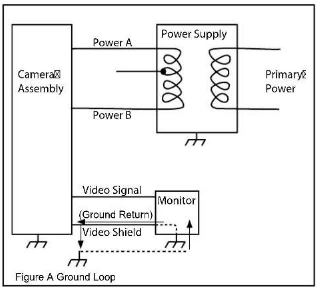
Generally a horizontal line on screen, whether moving or stationary, means you have a ground loop problem. The video shield should only be connected to ground through the monitor or other electronic equipment that uses the video signal. Connecting the video shield to ground at the camera will create a ground loop, which may interfere with the video signal (See Figure A). This should not damage the camera, but the video signal may become unusable. A ground loop problem will cause a dark horizontal bar to slowly "scroll" through the picture. To solve this problem, remove all ground connections from the video connection EXCEPT for the ground at the terminating end of the video signal.
The video termination should be a 75-ohm impedance, standard in monitors and other video equipment. If the video signal goes to more than one piece of equipment, a monitor and multiplexer input for instance, insure that one and only one piece of equipment terminates the video signal with 75 ohms; otherwise the image will be degraded and may appear to be unusually dim.
flowchart
graph TD
    A["Camera Assembly"] --> B["Power Supply"]
    B --> C["Monitor"]
    C --> D["Video Shield"]
    D --> E["Video Signal (Ground Return)"]
    E --> F["Power A"]
    E --> G["Power B"]
    H["Figure A Ground Loop"] --> C
    I["Primary Power"] --> B
IMPORTANT NOTE: If you have removed the ground loop and the horizontal line still remains on screen call Videolarm technical support for further information.
LINE LOCK
All cameras are all shipped from the factory with the line lock function disabled. If your application requires Line Lock contact Videolarm.
AUTOMATIC BROWN OUT FEATURE
The camera includes an automatic brown out feature which is activated whenever the incoming voltage drops below 10 VAC or VDC.
PICTURE IS CLEAR, LOW OR NO COLOR; PICTURE IS DARK OR GRAINY IN GOOD LIGHTING CONDITIONS
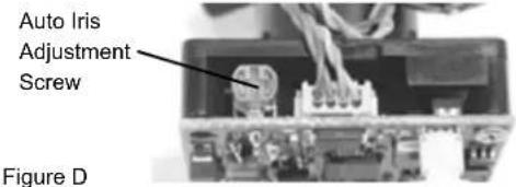
The auto iris lens is set at the factory. If you experience video too light or dark you can manually adjust using the auto iris adjustment screw.
If there is low or no color the Auto Iris is too open, if the picture is dark or grainy in good conditions the Auto Iris is too closed.
To adjust the auto iris lens, first locate the AUTO IRIS ADJUSTMENT SCREW on the camera PC board. Using a small insulated screwdriver (blade width of from 1/16" to 3/32"), adjust the control. Turning the control CLOCKWISE opens the iris, making the image brighter.
Turning the control COUNTER CLOCKWISE closes the iris, making the image darker.
SERIAL NUMBER CB CAMERAS
text_image
Auto Iris Adjustment Screw Figure DSERIAL NUMBER CT CAMERAS
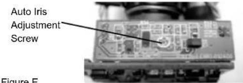
text_image
Auto Iris Adjustment Screw Figure EFigure E
IMPORTANT NOTE ON AUTO IRIS ADJUSTMENT:
WHEN ADJUSTING, USE A SMALL, INSULATED SCREW-DRIVER. The auto iris adjustments are very sensitive. Use gentle pressure when turning. To adjust, turn either clock-wise or counter-clockwise no more than one degree at a time. Check the monitor after each turn to determine is the desired brightness and color have been obtained. When the adjustment is satisfactory, place a hand over the lens to block out all light. Quickly remove the hand to be sure the iris reacts.
NVT TROUBLESHOOTING
If you are experiencing problems, attempt to simplify your setup. Test each cable segment separately. For example, test the camera and monitor together without the other equipment. Then add in the NVT transceivers, back-to-back. Test each segment of a long cable-run independently. Attempt to isolate the problem.
Below are problems that may be encountered. If the suggestions below are not helpful, or the recommendations are not effective, please call NVT's customer support. NVT customer support can be reached 8:00 AM to 5:30 PM PST at (800) 959-9870 or at (+1) (650) 562-0600.
FAINT OR BLURRY PICTURE; LITTLE OR NO COLOR
Possible causes include:
- Shielded twisted-pair cable. Verify that the wire is unshielded twisted-pair cable. Multi-pair cable with an overall shield is OK.
- Longer wire distance than expected. Be sure to include any coax cable that's part of this distance. Verify end-to-end connectivity with an ohm meter. Measure the distance by disconnecting the transceivers, shorting the far end, reading the loop's resistance at the near end. See above for ohm vs. distance ratings. If necessary, replace transceivers with correct models specified for this distance.
- Incorrect distance equalization setting. Adjust the equalization controls) with a mini screwdriver (NV-652R, NV-862R or the NV-1662R). If the transmitter is an NV-653T, verify correct equalization switch setting.
- Poor connection at a punch-block, splice, or coax cable. Re-check using the method described in #2 above, or use a wire test set.
- Short between conductors of the twisted-pair. Use an ohm meter to locate the short.
- Transient protection devices employing metal-oxide varistors. Use carbon blocks, gas-discharge tubes, or NVT transceivers with built-in protection.
- Check the camera. Are the focus and iris set correctly? Verify with portable monitor.
EXTREMELY FAINT PICTURE
Only faint shadows of the original picture are visible. One of the twisted pair conductors is open or the wires are shorted together. Check with an ohm meter.
OVER-SATURATED COLORS; HIGH CONTRAST GRAINY PICTURE; TOO BRIGHT, TORN PICTURE
Adjust the distance equalization as necessary. Verify that the monitor has a 75 termination, not in "loop-through".
WON'T SYNC; WIDE, WHITE JAGGED AREAS
Looks like a scrambled Cable TV signal. Check polarity.
WON'T SYNC; TORN PICTURE
- Make sure that you are using unshielded twisted pair wire.
- Check distance equalization settings.
- For installations with passive (non-amplified) transceivers at both ends, check for ground loops. This may be done with an AC Voltmeter, as shown below:
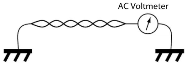
text_image
AC VoltmeterIf the voltage is greater than 1/2 volt, use an amplified receiver, such as the NV-652R, NV-862R, or NV-1662R.
Alternately, remove the ground at one end (usually at the camera end). Be sure that floating the camera conforms to local/regional and National Electrical Codes.
- Check for crosstalk from a second video path. Disconnect all other video sources. If the problem goes away, check for a split-pair or un-twisted wire.
FAINT STRIPES GLIDING UP OR DOWN THE SCREEN
These are caused by crosstalk from a second video path, or with ground-loops in installations employing passive models at both ends.
- To identify, disconnect all other video signals temporarily. If the interference goes away, check the wire to make sure the signal is traveling through a twisted pair. Is two-way video being sent more than 1,000 ft (300m) over Category 2 or 3 wire? If so, the send and receive signals may need to go in separate jacketed cables, or upgrade to Category 5 wire.
- Next, check for ground loops. See #3 above.
Check the blue "power" LED on powered NVT units. If the light is not on, the receiver is not getting power. Re-check the power source and connections.
If the green LED is on but the power LED is off, check that the power supply is floating. Grounding one side of the power input may cause this condition.
The NV-652R, NV-862R or NV-1662R series receiver/hub is not detecting a video signal. There is an open or shorted connection. Use a multimeter to locate the fault.
GHOSTS
Faint shadows of the original signal shifted to the right. This is caused by an impedance mismatch along the wire. Verify that the monitor is terminated with 75 (not in "loop-through".) Check that all wire is unshielded twisted pair. The high-frequency wire impedance should be 100. Check for bridge-taps (see below) either by inspecting wiring closet connections, or, if available, using a "Time-Domain Reflectometer" (T.D.R.), sometimes called a "cable tester".
If the faint shadows are not copies of the original picture, but from the picture of some other camera, check for crosstalk:
Is any portion of the wire un-twisted?
Are the signals from two cameras split between two pairs?
Is there a short between a conductor of one signal and a conductor of another?
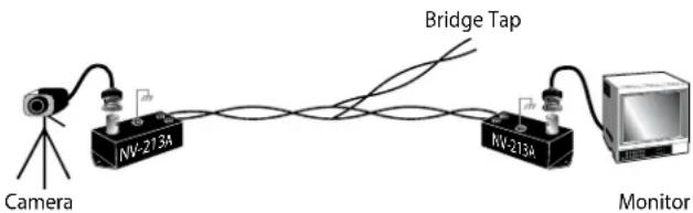
text_image
Camera NV-213A Bridge Tap NV-213A MonitorCABLE AND POWER GUIDELINES
This chart shows the proper current needed for power supplies for Warrior Series cameras. Use Class 2 Power only. Input voltage must be between 12-28 VDC or 15-28 VAC
| VOLTAGE | CURRENT | POWER |
| 12 VDC | 350mA | 4.2W |
| 24 VAC | 202mA | 4.8W |
Depending on the voltage being used, refer to one of the formulas below to select the correct power supply for cameras connected in parallel (positive to positive, negative to negative):
Total current for a 12 VDC system:
TOTAL CURRENT = (350mA x total number of cameras) Example: 350mA x 5 total cameras = 1750mA
Total current for a 24 VAC system:
TOTAL CURRENT = (202mA x total number of cameras) Example: 202mA x 5 total cameras = 1010mA
NOTE: If you're using a 12 VDC power supply and experience problems check the voltage at the camera's power input. This voltage should not
be less than 11 VDC. If you're measuring less than 11 VDC you'll need to use a power supply with a higher current rating.
Power Supply Cable Maximum Length (feet/meters)
| Total Load | Power Supply | 24 AWG | 22 AWG | 18 AWG | 16 AWG |
| 4.2W | 12 VDC | 55/16 | 88/26 | 223/67 | 355/108 |
| 4.8W | 24 VAC | 867/264 | 1380/420 | 3488/1063 | 5547/1690 |
NOTE: The above table is based on a "worst-case" power supply. Using a regulated or switching power supply can increase your cable distance. A CSA/UL listed Class 2 power supply must be used. Videolarm recommends its PS12 12 VDC 1000mA power supply for 12 VDC applications
Video Cable Maximum Length (feet/meters)
| Cable Type | RG-59 | RG-6 | RG-11 |
| Wire Gauge | 23 AWG* | 18 AWG* | 16 AWG* |
| Max. Length | 750/229 | 1500/457 | 1800/549 |
* Copper clad steel core, 95% braided shield
Maximum Length (feet/meters)
| AWG | 250/76 | 500/152 | 1000/305 | 1500/457 | 2000/610 | 3000/914 |
| 18 | 3Ω | 6Ω | 13Ω | 19Ω | 26Ω | 40Ω |
| 20 | 5Ω | 10Ω | 20Ω | 30Ω | 40Ω | 59Ω |
| 22 | 8Ω | 17Ω | 33Ω | 48Ω | 66Ω | 99Ω |
| 24 | 13Ω | 26Ω | 52Ω | 78Ω | 108Ω | 163Ω |
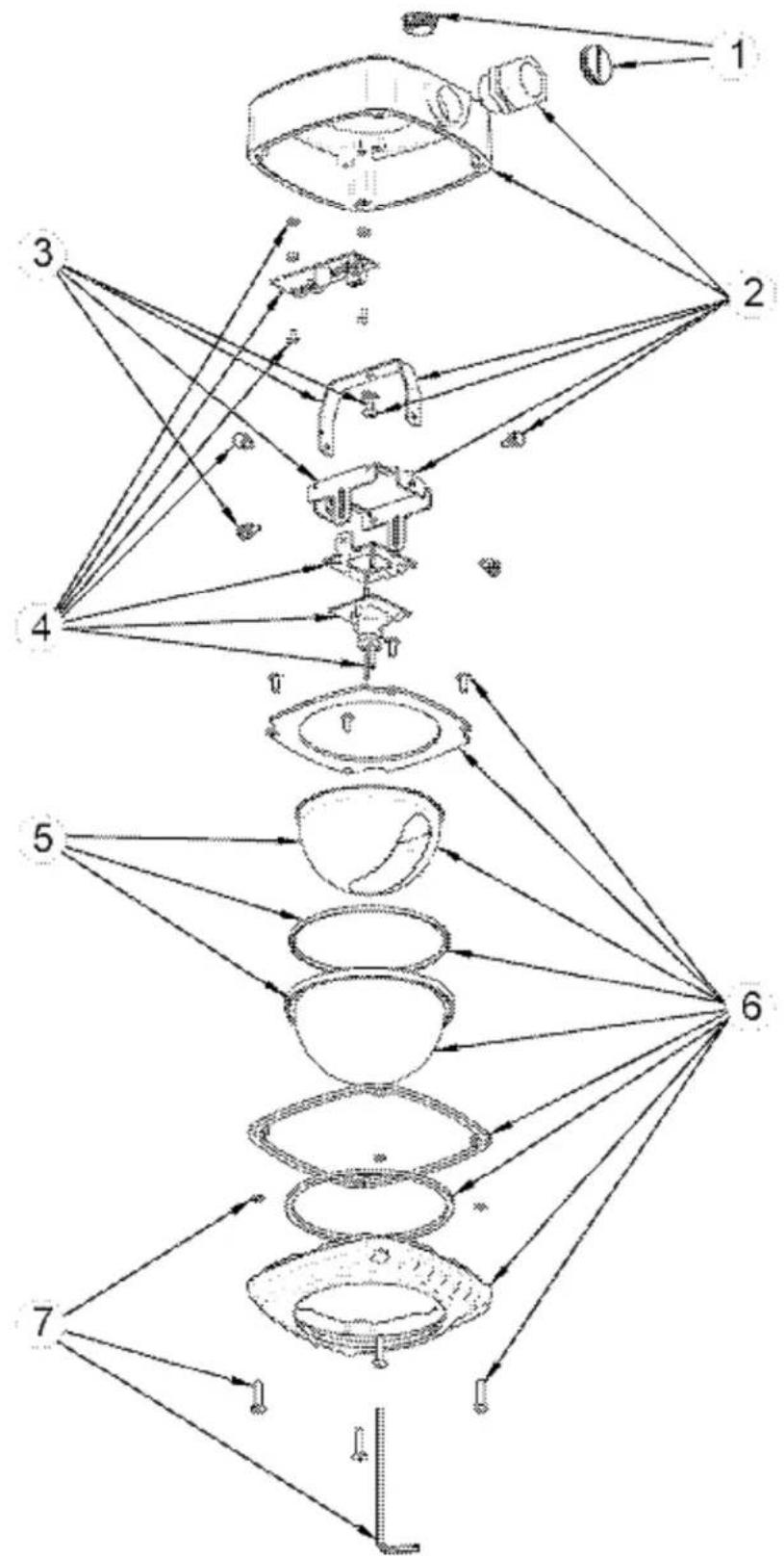
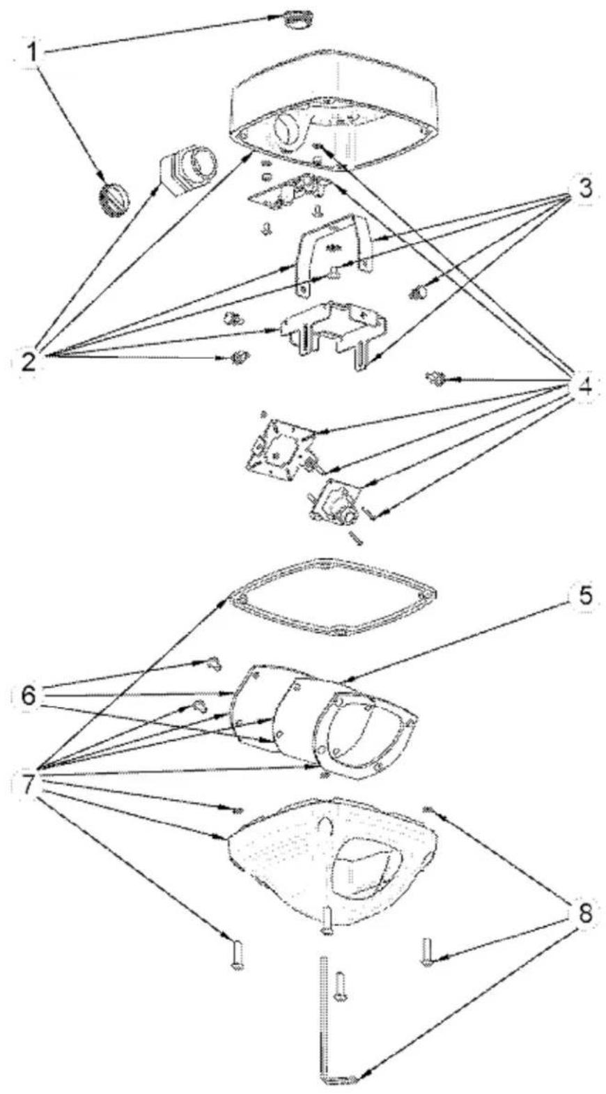
WS1 -
Exploded Diagram
flowchart
graph TD
    A["1"] --> B["2"]
    B --> C["3"]
    C --> D["4"]
    D --> E["5"]
    E --> F["6"]
    F --> G["7"]
    G --> H["Bottom Layer"]
    style A fill:#f9f,stroke:#333
    style B fill:#ccf,stroke:#333
    style C fill:#cfc,stroke:#333
    style D fill:#fcc,stroke:#333
    style E fill:#cff,stroke:#333
    style F fill:#ffc,stroke:#333
    style G fill:#cfc,stroke:#333
    style H fill:#fcc,stroke:#333
| Part Number | Description | |
| 1 RP | WS1010 PACKET | ASSEMBLY WARRIOR 1&3 HOUSINGS |
| 2 RP | WS1020 WARRIOR 1 & 3 BASE ASSEMBLY | |
| 3 RP | WS1030 WARRIOR 1 & 3 CARRIAGE ASSEMBLY KIT | |
| NTSC BOARD CAMERAS | ||
| 4 RP | WS1041F WARRIOR 1 & 2 STANDARD RES, BLACK & WHITE, FIXED CAMERA KIT | |
| RPWS1041V WARRIOR 1 & 2 STANDARD RES, BLACK & WHITE, VARIFOCAL CAMERA KIT | ||
| RPWS1043F WARRIOR 1 & 2 STANDARD RES, COLOR, FIXED CAMERA KIT | ||
| RPWS1043V WARRIOR 1 & 2 STANDARD RES, COLOR, VARIFOCAL CAMERA KIT | ||
| RPWS1043A WARRIOR 1 & 2 STANDARD RES, COLOR, AUTO-IRIS VARIFOCAL CAMERA KIT | ||
| RPWS1045F WARRIOR 1 & 2 HI-RES, COLOR, FIXED CAMERA KIT | ||
| RPWS1045V WARRIOR 1 & 2 HI-RES, COLOR, VARIFOCAL CAMERA KIT | ||
| RPWS1045A WARRIOR 1 & 2 HI-RES, COLOR, AUTO-IRIS VARIFOCAL CAMERA KIT | ||
| RPWS1046A WARRIOR 1 & 2 ULTRA HI-RES, COLOR, AUTO-IRIS VARIFOCAL CAMERA KIT | ||
| PAL BOARD CAMERAS | ||
| RPWS1041PF WARRIOR 1 & 2 PAL STANDARD RES, BLACK & WHITE, FIXED CAMERA KIT | ||
| RPWS1041PV WARRIOR 1 & 2 PAL STANDARD RES, BLACK & WHITE, VARIFOCAL CAMERA KIT | ||
| RPWS1043PF WARRIOR 1 & 2 PAL STANDARD RES, COLOR, FIXED CAMERA KIT | ||
| RPWS1043PV WARRIOR 1 & 2 PAL STANDARD RES, COLOR, VARIFOCAL CAMERA KIT | ||
| RPWS1043PA WARRIOR 1 & 2 PAL STANDARD RES, COLOR, AUTO-IRIS VARIFOCAL CAMERA KIT | ||
| RPWS1045PF WARRIOR 1 & 2 PAL HI-RES, COLOR, FIXED CAMERA KIT | ||
| RPWS1045PV WARRIOR 1 & 2 PAL HI-RES, COLOR, VARIFOCAL CAMERA KIT | ||
| RPWS1045PA WARRIOR 1 & 2 PAL HI-RES, COLOR, AUTO-IRIS VARIFOCAL CAMERA KIT | ||
| RPWS1046PA WARRIOR 1 & 2 PAL ULTRA HI-RES, COLOR, AUTO-IRIS VARIFOCAL CAMERA KIT | ||
| 5 | RPWS1050 | REPLACEMENT CAPSULE KIT FOR WARRIOR 1&2 (clear) |
| RPWS1051 | REPLACEMENT CAPSULE KIT FOR WARRIOR 1&2 (tinted) | |
| 6 | RPWS1060 | FRONT PLATE ASSEMBLY KIT WARRIOR 1 & 2 (CLEAR DOME) |
| RPWS1061 | FRONT PLATE ASSEMBLY KIT WARRIOR 1 & 2 (TINTED DOME) | |
| 7 RP | WS1070 WARRIOR 1-4 FACE PLATE FASTENER KIT | |
WS3
Exploded Diagram
| Part Number | Description | |
| 1 RP | WS1010 PACKET | ASSEMBLY WARRIOR 1 & 3 HOUSINGS |
| 2 RP | WS1020 WARRIOR 1 & 3 BASE ASSEMBLY | |
| 3 RP | WS1030 WARRIOR 1 & 3 CARRIAGE ASSEMBLY KIT | |
| NTSC BOARD CAMERAS | ||
| 4 RP | WS3041F WARRIOR 3 & 4 STANDARD RES, BLACK & WHITE, FIXED CAMERA KIT | |
| RPWS3041V WARRIOR 3 & 4 STANDARD RES, BLACK & WHITE, VARIFOCAL CAMERA KIT | ||
| RPWS3043F WARRIOR 3 & 4 STANDARD RES, COLOR, FIXED CAMERA KIT | ||
| RPWS3043V WARRIOR 3 & 4 STANDARD RES, COLOR, VARIFOCAL CAMERA KIT | ||
| RPWS3043A WARRIOR 3 & 4 STANDARD RES, COLOR, AUTO-IRIS VARIFOCAL CAMERA KIT | ||
| RPWS3045F WARRIOR 3 & 4 HI-RES, COLOR, FIXED CAMERA KIT | ||
| RPWS3045V WARRIOR 3 & 4 HI-RES, COLOR, VARIFOCAL CAMERA KIT | ||
| RPWS3045A WARRIOR 3 & 4 HI-RES, COLOR, AUTO-IRIS VARIFOCAL CAMERA KIT | ||
| RPWS3046A WARRIOR 3 & 4 ULTRA HI-RES, COLOR, AUTO-IRIS VARIFOCAL CAMERA KIT | ||
| PAL BOARD CAMERAS | ||
| RPWS3041PF WARRIOR 3 & 4 PAL STANDARD RES, BLACK & WHITE, FIXED CAMERA KIT | ||
| RPWS3041PV | WARRIOR 3 & 4 PAL STANDARD RES, BLACK & WHITE, VARIFOCAL CAMERA KIT | |
| RPWS3043PF WARRIOR 3 & 4 PAL STANDARD RES, COLOR, FIXED CAMERA KIT | ||
| RPWS3043PV | WARRIOR 3 & 4 PAL STANDARD RES, COLOR, VARIFOCAL CAMERA KIT | |
| RPWS3043PA WARRIOR 3 & 4 PAL STANDARD RES, COLOR, AUTO-IRIS VARIFOCAL CAMERA KIT | ||
| RPWS3045PF | WARRIOR 3 & 4 PAL HI-RES, COLOR, FIXED CAMERA KIT | |
| RPWS3045PV | WARRIOR 3 & 4 PAL HI-RES, COLOR, VARIFOCAL CAMERA KIT | |
| RPWS3045PA WARRIOR 3 & 4 PAL HI-RES, COLOR, AUTO-IRIS VARIFOCAL CAMERA KIT | ||
| RPWS3046PA WARRIOR 3 & 4 PAL ULTRA HI-RES, COLOR, AUTO-IRIS VARIFOCAL CAMERA KIT | ||
| 5 WS | 3PS WARRIOR 3 & 4 REPLACEMENT PAINT SHIELD | |
| 6 RP | WS3060 REPLACEMENT WINDOW KIT | |
| 7 RP | WS3070 WEDGE ASSEMBLY KIT | |
| 8 RP | WS1070 WARRIOR 1-4 FACE PLATE FASTENER KIT | |
IMPORTANT SAFEGUARDS SAFETY PRECAUTIONS
1 Read these instructions.
2 Keep these instructions.
3 Heed all warnings
4 Follow all instructions.
5 Do not use this apparatus near water.
6 Clean only with damp cloth.
7 Do not block any of the ventilation openings. Install in accordance with the manufacturers instructions.
8 Cable Runs- All cable runs must be within permissible distance.
9 Mounting - This unit must be properly and securely mounted to a supporting structure capable of sustaining the weight of the unit.
Accordingly:
a. The installation should be made by a qualified installer.
b. The installation should be in compliance with local codes.
c. Care should be exercised to select suitable hardware to install the unit, taking into account both the composition of the mounting surface and the weight of the unit.
10 Do not install near any heat sources such as radiators, heat registers, stoves, or other apparatus (including amplifiers) that produce heat.
11 Do not defeat the safety purpose of the polarized or grounding-type plug. A polarized plug has two blades with one wider than the other. A grounding type plug has two blades and a third grounding prong. The wide blade or the third prong are provided for your safety. When the provided plug does not fit into your outlet, consult an electrician for replacement of the obsolete outlet.
12 Protect the power cord from being walked on or pinched particularly at plugs, convenience receptacles, and the point where they exit from the apparatus.
13 Only use attachment/ accessories specified by the manufacturer.
14 Use only with a cart, stand, tripod, bracket, or table specified by the manufacturer, or sold with the apparatus. When a cart is used, use caution when moving the cart/ apparatus combination to avoid injury from tip-over.
15 Unplug this apparatus during lighting storms or when unused for long periods of time.
16 Refer all servicing to qualified service personnel. Servicing is required when the apparatus has been damaged in any way, such as power-supply cord or plug is damaged, liquid has been spilled of objects have fallen into the apparatus, the apparatus has been exposed to rain or moisture, does not operate normally, or has been dropped.
Be sure to periodically examine the unit and the supporting structure to make sure that the integrity of the installation is intact. Failure to comply with the foregoing could result in the unit separating from the support structure and falling, with resultant damages or injury to anyone or anything struck by the falling unit.
UNPACKING
Unpack carefully. Electronic components can be damaged if improperly handled or dropped. If an item appears to have been damaged in shipment, replace it properly in its carton and notify the shipper.
Be sure to save:
1 The shipping carton and packaging material. They are the safest material in which to make future shipments of the equipment.
2 These Installation and Operating Instructions.
SERVICE
If technical support or service is needed, contact us at the following number:
TECHNICAL SUPPORT
AVAILABLE 24 HOURS
1-800-554-1124
CAUTION
RISK OF ELECTRIC SHOCK DO NOT OPEN

CAUTION: TO REDUCE THE RISK OF ELECTRIC SHOCK, DO NOT REMOVE COVER ( OR BACK). NO USER- SERVICE-ABLE PARTS INSIDE. REFER SEVICING TO QUALIFIED SERVICE PERSONNEL.
The lightning flash with an arrowhead symbol, within an equilateral triangle, is intended to alert the user to the presence of non-insulated "dangerous voltage" within the product's enclosure that may be of sufficient magnitude to constitute a risk to persons.
The exclamation point within an equilateral triangle is intended to alert the user to presence of important operating and maintenance (servicing) instructions in the literature accompanying the appliance.
PRODUCTCATEGORY PARTS LABOR
| All Enclosures and Electronics | Five (5) Years | Five (5) Years | ||
| Pan/Tilts | Three (3) Years | **6 months if used in autoscan /tour operation | Three (3) Years | **6 months if used in autoscan /tour operation |
| Poles/PoleEvators | Three (3) Years | Three (3) Years | ||
| Warrior/Q-View/I.R. Illuminators | Five (5) Years | Five (5) Years | ||
| SView Series Five (5) Years | **6 months if used in autoscan /tour operation | Five (5) Years | **6 months if used in autoscan /tour operation | |
| Controllers | Five (5) Years | Five (5) Years | ||
| Power Supplies | Five (5) Years | Five (5) Years | ||
| Accessory Brackets | Five (5) Years | Five (5) Years |
During the labor warranty period, to repair the Product, Purchaser will either return the defective product, freight prepaid, or deliver it to Videolarm Inc. Decatur GA. The Product to be repaired is to be returned in either its original carton or a similar package affording an equal degree of protection with a RMA # (Return Materials Authorization number) displayed on the outer box or packing slip. To obtain a RMA# you must contact our Technical Support Team at 800.554.1124, extension 101. Videolarm will return the repaired Product freight prepaid to Purchaser. Videolarm is not obligated to provide Purchaser with a substitute unit during the warranty period or at any time. After the applicable warranty period, Purchaser must pay all labor and/or parts charges.
The limited warranty stated in these product instructions is subject to all of the following terms and conditions:
TERMS AND CONDITIONS
-
NOTIFICATION OF CLAIMS: WARRANTY SERVICE: If Purchaser believes that the Product is defective in material or workmanship, then written notice with an explanation of the claim shall be given promptly by Purchaser to Videolarm but all claims for warranty service must be made within the warranty period. If after investigation Videolarm determines that the reported problem was not covered by the warranty, Purchaser shall pay Videolarm for the cost of investigating the problem at its then prevailing per incident billable rate. No repair or replacement of any Product or part thereof shall extend the warranty period as to the entire Product. The specific warranty on the repaired part only shall be in effect for a period of ninety (90) days following the repair or replacement of that part or the remaining period of the Product parts warranty, whichever is greater.
-
EXCLUSIVE REMEDY: ACCEPTANCE: Purchaser's exclusive remedy and Videolarm's sole obligation is to supply (or pay for) all labor necessary to repair any Product found to be defective within the warranty period and to supply, at no extra charge, new or rebuilt replacements for defective parts.
-
EXCEPTIONS TO LIMITED WARRANTY: Videolarm shall have no liability or obligation to Purchaser with respect to any Product requiring service during the warranty period which is subjected to any of the following: abuse, improper use: negligence, accident, lightning damage or other acts of God (i.e., hurricanes, earthquakes), modification, failure of the end-user to follow the directions outlined in the product instructions, failure of the end-user to follow the maintenance procedures recommended by the International Security Industry Organization, written in product instructions, or recommended in the service manual for the Product. Furthermore, Videolarm shall have no liability where a schedule is specified for regular replacement or maintenance or cleaning of certain parts (based on usage) and the end-user has failed to follow such schedule; attempted repair by non-qualified personnel; operation of the Product outside of the published environmental and electrical parameters, or if such Product's original identification (trademark, serial number) markings have been defaced, altered, or removed. Videolarm excludes from warranty coverage Products sold AS IS and/or WITH ALL FAULTS and excludes used Products which have not been sold by Videolarm to the Purchaser. All software and accompanying documentation furnished with, or as part of the Product is furnished "AS IS" (i.e., without any warranty of any kind), except where expressly provided otherwise in any documentation or license agreement furnished with the Product.
-
PROOF OF PURCHASE: The Purchaser's dated bill of sale must be retained as evidence of the date of purchase and to establish warranty eligibility. DISCLAIMER OF WARRANTY
EXCEPT FOR THE FOREGOING WARRANTIES, VIDEOLARM HEREBY DISCLAIMS AND EXCLUDES ALL OTHER WARRANTIES, EXPRESS OR IMPLIED, INCLUDING, BUT NOT LIMITED TO ANY AND/OR ALL IMPLIED WARRANTIES OF MERCHANTABILITY, FITNESS FOR A PARTICULAR PURPOSE AND/OR ANY WARRANTY WITH REGARD TO ANY CLAIM OF INFRINGEMENT THAT MAY BE PROVIDED IN SECTION 2-312(3) OF THE UNIFORM COMMERCIAL CODE AND/OR IN ANY OTHER COMPARABLE STATE STATUTE. VIDEOLARM HEREBY DISCLAIMS ANY REPRESENTATIONS OR WARRANTY THAT THE PRODUCT IS COMPATIBLE WITH ANY COMBINATION OF NON-VIDEOLARM PRODUCTS OR NON-VIDEOLARM RECOMMENDED PRODUCTS PURCHASER CHOOSES TO CONNECT TO PRODUCT.
LIMITATION OF LIABILITY
THE LIABILITY OF VIDEOLARM, IF ANY, AND PURCHASER'S SOLE AND EXCLUSIVE REMEDY FOR DAMAGES FOR ANY CLAIM OF ANY KIND WHATSOEVER, REGARDLESS OF THE LEGAL THEORY AND WHETHER ARISING INTORT OR CONTRACT, SHALL NOT BE GREATER THAN THE ACTUAL PURCHASE PRICE OF THE PRODUCT WITH RESPECT TO WHICH SUCH CLAIM IS MADE. IN NO EVENT SHALL VIDEOLARM BE LIABLE TO PURCHASER FOR ANY SPECIAL, INDIRECT, INCIDENTAL, OR CONSEQUENTIAL DAMAGES OF ANY KIND INCLUDING, BUT NOT LIMITED TO, COMPENSATION, REIMBURSEMENT OR DAMAGES ON ACCOUNT OF THE LOSS OF PRESENT OR PROSPECTIVE PROFITS OR FOR ANY OTHER REASON WHATSOEVER.
Product Registration/Warranty
Thank you for choosing Videolarm. We value your patronage and are solely committed to providing you with only the highest quality products available with unmatched customer service levels that are second-to-none in the security industry.
Should a problem arise, rest assure that Videolarm stands behind its products by offering some of the most impressive warranty plans available: 3 Years on all Housings, Poles, Power Supplies, and Accessories and 5 Years on all camera systems (SView, QView, Warriors), and InfraRed Illuminators.

text_image
THREE YEAR 3 WARRANTY FIVE YEAR 5 WARRANTYRegister Your Products
Option 1: Online Option 2: Mail-In
Take a few moments and validate your purchase with our Online Product Registration Form at www.videolarm.com/productregistration.jsp or complete and mail-in the bottom portion of this flyer.
Register your recent Videolarm purchases and benefit from the following:
- Simple and Trouble-Free RMA process
- Added into customer database to receive product updates / news
- Eliminate the need to archive original purchase documents:
Receipts, Purchase Orders, etc...

Cut at the dotted Line
Place in envelope, affix stamp and mail to:
Videolarm ATTN: Warranty 2525 Park Central Ave. Decatur, GA 30035
Main Contact Info
First Name: Last Name:
Professional Title: ____ Company: ____
Address 1: Address 2:
City: State / Province/Country:
Zip / Postal Code: Phone Number: E-mail Address: ____
Product Information
Please Circle One: Business
Personal
Name & Location of Company / Store where Purchased:
(City, State, Country)
Videolarm Product ID Product Description
Serial #
(Available only for Camera Systems, IR Illuminators, Wireless Devices)
PO#