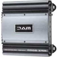
MPX 2000 - Receiver MAC AUDIO - Free user manual and instructions
Find the device manual for free MPX 2000 MAC AUDIO in PDF.



| Product type | 4-channel power amplifier for car radio |
| Brand | MAC AUDIO |
| Model | MPX 2000 |
| Maximum output power (stereo, 4 Ohm) | 4 x 180 W (1 kHz, burst) |
| RMS power (stereo, 4 Ohm) | 4 x 60 W (DIN 45324) |
| Maximum output power (bridged, 4 Ohm) | 2 x 500 W (1 kHz, burst) |
| RMS power (bridged, 4 Ohm) | 2 x 160 W (DIN 45324) |
| Speaker impedance (stereo) | 2 to 8 Ohm |
| Frequency response | 5 – 50,000 Hz (-3 dB) |
| Total harmonic distortion | < 0.05% (1 kHz) |
| Crosstalk attenuation | > 60 dB (1 kHz) |
| Signal-to-noise ratio | > 100 dB (IEC A) |
| Input sensitivity (LOW LEVEL) | 400 mV – 4 V |
| Input impedance (LOW LEVEL) | 20 kOhm |
| Low-pass filter | 40 – 300 Hz, 12 dB/octave, adjustable |
| High-pass filter | 40 – 300 Hz, 12 dB/octave, adjustable |
| Bass Boost | 0…12 dB at 45 Hz |
| Power supply | +12 V (9 – 15 V), negative ground |
| Fuse | 2 × 15 A |
| Operating modes | 4/3/2 channels, bridgeable, Tri mode |
| Protections | Short circuit, DC offset, thermal overload |
| LED indicators | Green (on), Red (overload) |
| Line outputs (LINE OUT) | Composite signal for external subwoofer amplifier |
| Maintenance | Clean with a dry cloth, avoid abrasive products |
| Warranty | 2 years (valid for the first owner) |
Frequently Asked Questions - MPX 2000 MAC AUDIO
User questions about MPX 2000 MAC AUDIO
0 question about this device. Answer the ones you know or ask your own.
Ask a new question about this device
Download the instructions for your Receiver in PDF format for free! Find your manual MPX 2000 - MAC AUDIO and take your electronic device back in hand. On this page are published all the documents necessary for the use of your device. MPX 2000 by MAC AUDIO.
USER MANUAL MPX 2000 MAC AUDIO
At the end of the product's useful life, please dispose of it at appropriate collection points provided in your country.
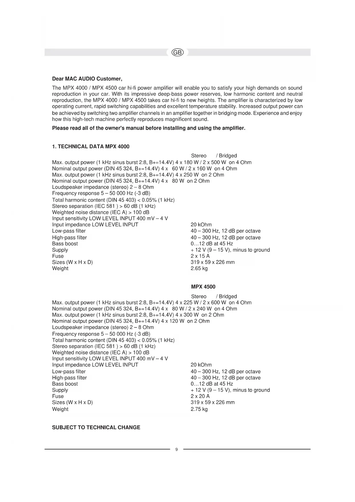
The MPX 4000 / MPX 4500 car hi-fi power amplifier will enable you to satisfy your high demands on sound reproduction in your car. With its impressive deep-bass power reserves, low harmonic content and neutral reproduction, the MPX 4000 / MPX 4500 takes car hi-fi to new heights. The amplifier is characterized by low operating current, rapid switching capabilities and excellent temperature stability. Increased output power can be achieved by switching two amplifier channels in an amplifier together in bridging mode. Experience and enjoy how this high-tech machine perfectly reproduces magnificent sound.
Please read all of the owner's manual before installing and using the amplifier.
1. TECHNICAL DATA MPX 4000
Stereo / Bridged
Max. output power (1 kHz sinus burst 2:8, B+=14.4V) 4 x 180 W / 2 x 500 W on 4 Ohm
Nominal output power (DIN 45 324, B+=14.4V) 4 x 60 W / 2 x 160 W on 4 Ohm
Max. output power (1 kHz sinus burst 2:8, B+=14.4V) 4 x 250 W on 2 Ohm
Nominal output power (DIN 45 324, B+=14.4V) 4 x 80 W on 2 Ohm
Loudspeaker impedance (stereo) 2 - 8 Ohm
Frequency response 5 – 50 000 Hz (-3 dB)
Total harmonic content (DIN 45 403) < 0.05% (1 kHz)
Stereo separation (IEC 581) > 60 dB (1 kHz)
Weighted noise distance (IEC A) > 100 dB
Input sensitivity LOW LEVEL INPUT 400 mV - 4 V
Input impedance LOW LEVEL INPUT
Low-pass filter
High-pass filter
Bass boost
Supply
Fuse
Sizes (W x H x D)
Weight
20 kOhm
40 – 300 Hz, 12 dB per octave
40 – 300 Hz, 12 dB per octave
0...12 dB at 45 Hz
+ 12 V (9 - 15 V), minus to ground
2 × 15 A
319 x 59 x 226 mm
2.65 kg
MPX 4500
Stereo / Bridged
Max. output power (1 kHz sinus burst 2:8, B+=14.4V) 4 x 225 W / 2 x 600 W on 4 Ohm
Nominal output power (DIN 45 324, B+=14.4V) 4 x 80 W / 2 x 240 W on 4 Ohm
Max. output power (1 kHz sinus burst 2:8, B+=14.4V) 4 x 300 W on 2 Ohm
Nominal output power (DIN 45 324, B+=14.4V) 4 x 120 W on 2 Ohm
Loudspeaker impedance (stereo) 2 - 8 Ohm
Frequency response 5 – 50 000 Hz (-3 dB)
Total harmonic content (DIN 45 403) < 0.05% (1 kHz)
Stereo separation (IEC 581) > 60 dB (1 kHz)
Weighted noise distance (IEC A) > 100 dB
Input sensitivity LOW LEVEL INPUT 400 mV - 4 V
Input impedance LOW LEVEL INPUT
Low-pass filter
High-pass filter
Bass boost
Supply
Fuse
Sizes (W x H x D)
Weight
20 kOhm
40 – 300 Hz, 12 dB per octave
40 – 300 Hz, 12 dB per octave
0...12 dB at 45 Hz
+ 12 V (9 - 15 V), minus to ground
2 × 20 A
319 × 59 × 226 mm
2.75 kg
SUBJECT TO TECHNICAL CHANGE
2. FEATURES
- Complementary push-pull final stage
· Automatic switching on/off via car radio
· Infinitely adjustable high pass and low pass filters
· Infinitely variable bass equalisation - Adjustable input sensitivity
· Bridgeable 4-/3-/2-channel mode - Tri-mode
- Electronic protective circuit against short circuiting, DC offset and excess temperature
- Mute switch for suppressing switch-on crackle interference
- Low-level outputs (cinch jacks) for connecting a subwoofer amplifier
- Status indicator (green LED) and overload indicator (red LED)
3. IMPORTANT INSTALLATION INFORMATION
· This appliance may only be connected to a 12 volt system with negative ground.
- The heat radiated when the amplifier is used means that sufficient air circulation is required at the place of installation. It is very important that the cooler's cooler ribs do not contact any metal plating or any surfaces which could impair air circulation. The amplifier may not be installed in small confined spaces or spaces without air circulation (e.g. spare wheel recess or under the vehicle carpeting). Installation in the boot is recommended.
- Install the amplifier in such a way that it is protected as far as possible against vibrations and dust and dirt.
- Make sure that the input/output cables are sufficiently distant from the power supply cables as otherwise interference may occur.
- Make sure that the fuse and operating elements are accessible after installation.
- The appliance's reliability and performance depend on the quality of installation. Preferably get an expert to install the system, particularly if you want to install several loudspeakers or a complex multi-way system.
4. CONNECTIONS
4.1 POWER SUPPLY AND AUTOMATIC SWITCHING ON
Important notice: Before commencing the installation, disconnect the plus terminals from the car battery in order to prevent short circuits.
The power cabling usually installed in on-board car networks is not sufficient for a power amplifier's demands. Make sure that the power lines to GND and to the +12 V terminal have been sufficiently specified. Acable cross-section of at least 12 mm^2 must be used to connect the battery to the amplifier's terminals.
First connect the amplifier's GND terminal to the battery's minus pole. It is very important that the connection is good. Dirt residues must be carefully removed from the battery's connection point. A loose connection may cause malfunctions or interference noise or distortion.
The +12 V amplifier connection must then be connected with a power cable possessing an integrated fuse to the battery's plus pole. The fuse should be located close to the battery; for safety reasons, the cable from the positive terminal of the battery to the fuse must not exceed 60 cm in length. Only insert the fuse when all installation work, including the connection of the loudspeakers, has been completed.
Now connect the car hi-fi receiver's remote control connection to the amplifier's REM control jack. A cable with a cross-section of 0.75 mm^2 is sufficient for connecting the amplifier's REMOTE connection and the control device.
4.2 AUDIO CABLES
When installing the audio cable between the cinch output of your car receiver and the cinch input of the amplifier inside your car, the audio and power supply cables should, wherever possible, not be routed along the same side of the vehicle. We recommend an isolated installation, e.g. routing the power cable through the cable duct on the left-hand side and the audio cable through the cable duct on the right-hand side or vice versa. This reduces interference due to crosstalk into the audio cables.
4.3 LOUDSPEAKER CONNECTIONS
- In normal operating mode (i.e. one loudspeaker on each individual amplifier channel), the lowest terminal resistance is 2 ohm per channel.
- In bridging mode (two amplifier outputs combined) the lowest terminal resistance doubles to 4 ohm.
· The impedance in tri-mode may not fall below 2 ohm per channel. - Never connect the loudspeakers' minus terminals to the vehicle chassis.
- Never connect the +12 V supply voltage to a loudspeaker output as this would destroy the amplifier final stage.
If the amplifier is operated with lower terminal resistances or incorrectly used as described above, both the amplifier and the loudspeakers may be damaged. The warranty becomes void in such cases.
5. OPERATING ELEMENTS AND IN/OUTPUTS
5.1 SETTING THE INPUT SENSITIVITY
The input sensitivity may be adapted to any car radio or tape deck. Turn the volume control of your radio to its central position and then adjust the input-level controls (3) and (4) to produce an average medium volume. This setting usually provides sufficient power reserves at optimum weighted noise voltage.
ATTENTION: only reproduce loud test noises briefly to prevent damaging the loudspeakers.
5.2 LOW-PASS FILTER WITH ADJUSTABLE CROSS-OVER FREQUENCY
If the amplifier is used as a subwoofer amplifier, set the switch (9)/(10) to "LPF". Set the desired cross-over frequency using the control (7)/(8). This makes the filter adaptable to the installed woofer's sound requirements. The filter's high edge steepness is responsible for the precision reduction of medium and high frequency ranges.
5.3 HIGH-PASS FILTER WITH ADJUSTABLE CROSS-OVER FREQUENCY
If the amplifier is to be used as an amplifier for satellite loudspeakers (mid-range/tweeter loudspeakers), set switch (9)/(10) to "HPF". Set the desired cross-over frequency using the control (11)/(12). Only the frequencies above the set cross-over frequency will then be amplified. This effectively minimizes distortions caused by excessive membrane movement at low frequencies and small satellite loudspeakers without reducing the bass level.
5.4 BASS-BOOST
The bass-boost function (5/6) is used to increase or equalize the lower bass frequencies.
5.5 OUTPUTS FOR CONNECTING ADDITIONAL AMPLIFIERS
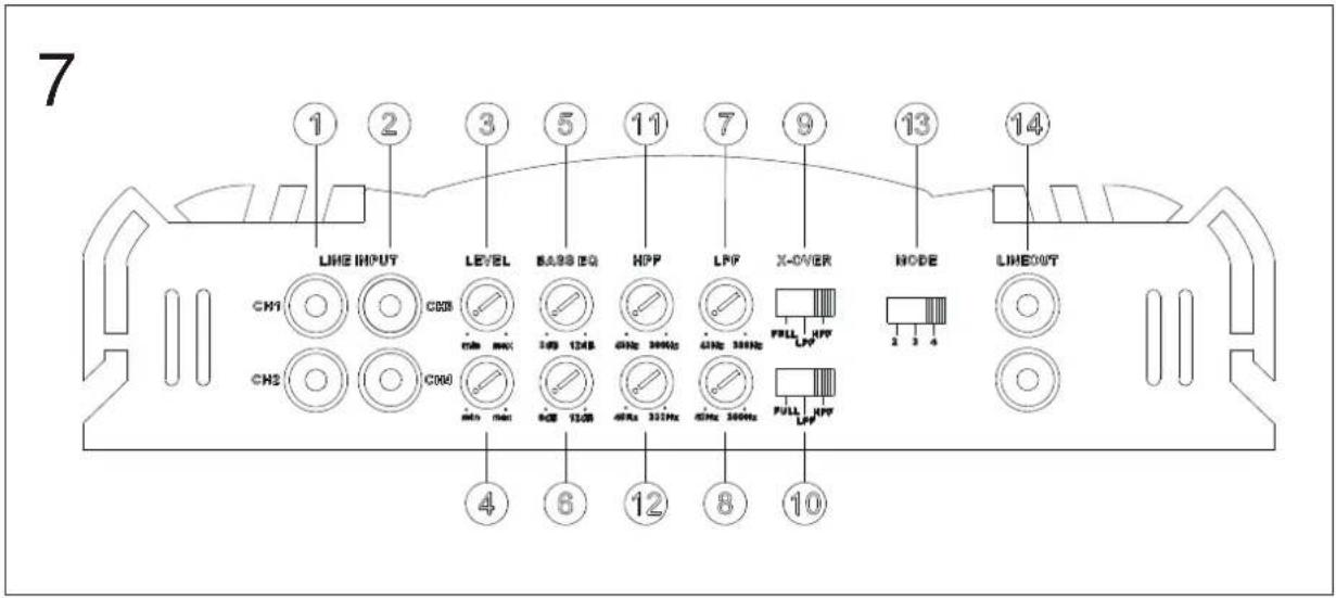
The input signal of the LINE INPUT connections CH1, CH2, CH3, CH4 (1 and 2, Fig. 7) is accumulated and forwarded directly to the LINE OUT (14) jacks. The LINE OUT connections allow the use of a subwoofer amplifier without requiring additional T-plugs and cables.
FIG. 1 POWER SUPPLY / REMOTE SWITCH-ON CONNECTIONS
(1) GND terminal for the ground, to the battery's minus pole
(2) REM terminal for remote switch-on
(3) Terminal for + 12 V battery voltage
(4) Battery
(5) Cable fuse
(6) To your car radio's automatic aerial connection
If your car is not equipped with an automatic aerial connection, connect this cable's plus pole (+) to the ignition lock. An on/off switch should be inserted in this case. Make sure that this switch is switched off if the amplifier is not used.
FIG. 2 4-CHANNEL MODE
Connect and set the amplifier as shown in Fig. 2 if it is to be controlled by a car radio with four output channels and used with four loudspeakers:
(1) To the car radio, front left output
(2) To the car radio, front right output
(3) To the car radio, rear left output
(4) To the car radio, rear right output
(5) Front left loudspeaker
(6) Front right loudspeaker
(7) Rear left loudspeaker
(8) Rear right loudspeaker
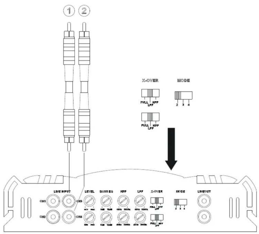
FIG. 3/4 3-CHANNEL MODE
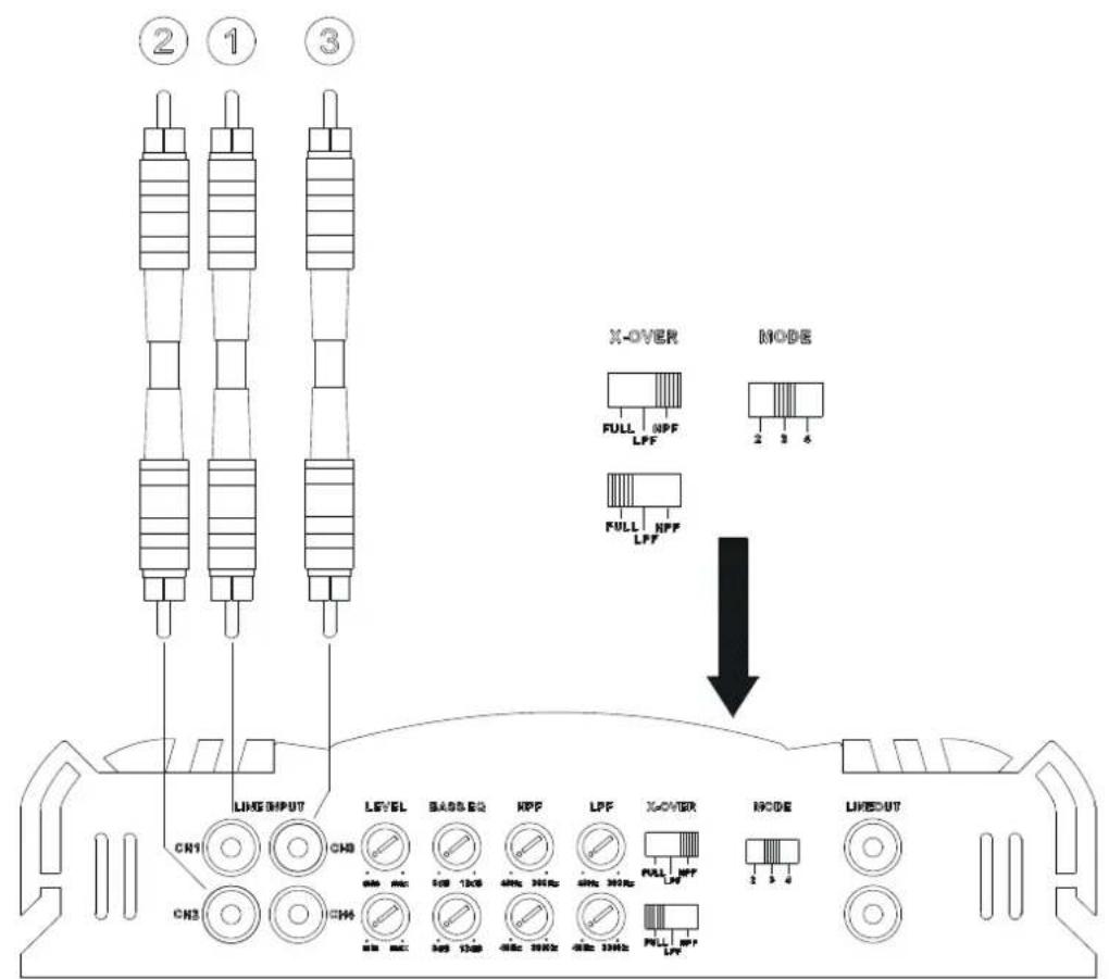
The 3-channel mode uses the high-pass filter for channels 1/2 and the low-pass filter for Channels 3/4. Section 5 describes how they are used.
FIG. 3
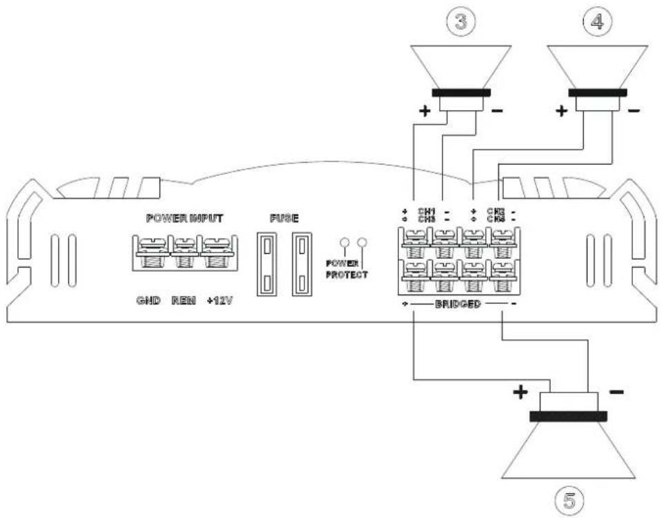
Connect and set the amplifier as shown in Fig. 3 if it is to be controlled by a car radio with stereo output and used with stereo satellite loudspeakers and a subwoofer.
(1) To the car radio, left output
(2) To the car radio, right output
(3) Left satellite loudspeaker
(4) Right satellite loudspeaker
(5) Subwoofer
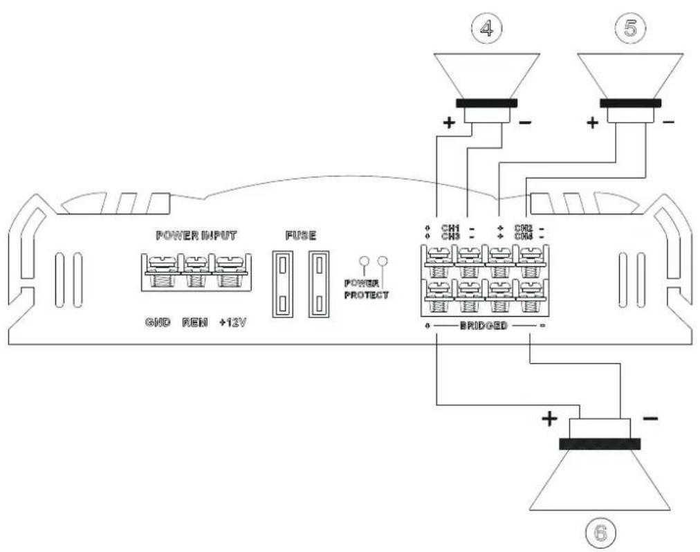
FIG. 4
Connect and set the amplifier as shown in Fig. 4 if it is to be controlled by a car radio with stereo receiver and separate subwoofer output and used with stereo satellite loudspeakers and a subwoofer.
(1) To the car radio, left output
(2) To the car radio, right output
(3) To the car radio, subwoofer output
(4) Left satellite loudspeaker
(5) Right satellite loudspeaker
(6) Subwoofer
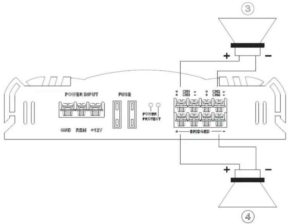
FIG. 5 2-CHANNEL MODE
If the amplifier has to generate more power to operate two subwoofers, connect and set it as shown in Fig. 5. The use of the low-pass filter used is described in Chapter 5.
(1) To the car radio, left output
(2) To the car radio, right output
(3) Subwoofer
(4) Subwoofer
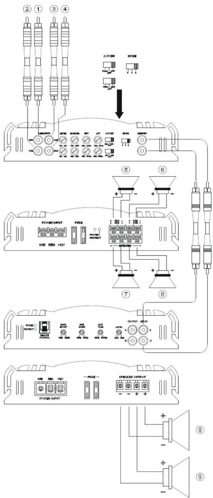
FIG. 6 USE AS AN AMPLIFIER FOR 4 SATELLITE LOUDSPEAKERS AND A SUBWOOFER USING AN ADDITIONAL 1-CHANNEL AMPLIFIER (MPX MONO)
(1) To the car radio, front left output
(2) To the car radio, front right output
(3) To the car radio, rear left output
(4) To the car radio, rear right output
(5) Front left loudspeaker
(6) Front right loudspeaker
(7) Rear left loudspeaker
(8) Rear right loudspeaker
(9) Subwoofer
FIG. 7 OPERATING ELEMENTS AND IN/OUTPUTS
(1) Low-level inputs (channel 1/2, front)
(2) Low-level inputs (channel 3/4, rear)
(3) Input-level control channel 1/2
(4) Input-level control channel 3/4
(5) Bass-booster control (channel 1/2, front)
(6) Bass-booster control (channel 3/4, rear)
(7) FULL / LPF (low pass filter) / (HPF) high pass filter option switch for channel 1/2
(8) FULL / LPF (low pass filter) / (HPF) high pass filter option switch for channel 3/4
(9) Low-pass selector ON/OFF for channel 1/2
(10) Low-pass selector ON/OFF for channel 3/4
(11) Cross-over frequency control for the high pass (channel 1/2)
(12) Cross-over frequency control for the high pass (channel 3/4)
(13) Channel mode selector switch
(14) Low level outputs (Compound signal from CH1, CH2, CH3 and CH4)
Cher client de MAC AUDIO,
Dimensions (L x H x P))
319 x 59 x 226 mm
Poids
2,65 kg
MPX 4500
Stéréo / ponté
Dimensions (L x H x P))
319 x 59 x 226 mm
Poids
2,75 kg
SOUS TOUTES RESERVES DE MODIFICATIONS TECHNIQUES
2. PARTICULARITES
Dimensioni (L x A x P)
319 x 59 x 226 mm
Peso
2,65 kg
MPX 4500
Stereo / a ponte
Dimensioni (L x A x P)
319 x 59 x 226 mm
Peso
2,75 kg
CON RISERVA DI APPORTARE MODIFICHE TECNICHE
2. PARTICOLARITÀ
4.3 HÖGTALARANSLUTNINGAR
4
5
6
D
GB Congratulations! You have made a wise selection in becoming the owner of a MAC AUDIO HiFi equipment. Due to high quality MAC AUDIO products have earned an excellent reputation through the western world. And this high quality standard enables us to grant a 2-years warranty for Mac audio HiFi-electronic components.
The equipments are checked and tested continuously during the entire production process. In case you have problems with your MAC AUDIO HiFi equipment, kindly observe the following:
- The guarantee period commences with the purchase of the component and is applicable only to the original owner.
- During the guarantee period we will rectify any defects due to faulty material or workmanship by replacing or repairing the defective part at our discretion. Further claims, and in particular those for price reduction, cancellation of sale, compensation for damages or subsequential damages, are excluded. The guarantee period is not altered by the fact that we have carried out guarantee work.
- Unauthorized tampering with the equipment will invalidate this guarantee.
- Consult your authorized dealer first, if guarantee service is needed. Should it prove necessary to return the component to the factory, please insure that • the component is packed in original factory packing in good condition • the quality control card has been filled out and enclosed with the component, • your enclose your receipt as proof of purchase.
- Excluded from the guarantee are: • Illuminates • Wear parts • Shipping damages, either readily apparent or concealed (claims for such damages must be lodged immediately with forwarding agent, the railway express office or post office). • Scratches in cases, metal components, front panels, etc. (You must notify your dealer directly of such defects within three days of purchase.) • Defects caused by incorrect installation or connection, by operation errors (see operating instructions), by overloading or by external force. • Equipments which have been repaired incorrectly or modified or where the case has been opened by persons other than us. • Consequential damages to other equipments. • Reimbursement of cools, without our prior consent, when repairing damages by third parties.
F
Toutes nos félicitations!



- TECHNICAL DATA MPX 4000
- MPX 4500
- SUBJECT TO TECHNICAL CHANGE
- FEATURES
- IMPORTANT INSTALLATION INFORMATION
- CONNECTIONS
- POWER SUPPLY AND AUTOMATIC SWITCHING ON
- AUDIO CABLES
- LOUDSPEAKER CONNECTIONS
- OPERATING ELEMENTS AND IN/OUTPUTS
- SETTING THE INPUT SENSITIVITY
- LOW-PASS FILTER WITH ADJUSTABLE CROSS-OVER FREQUENCY
- HIGH-PASS FILTER WITH ADJUSTABLE CROSS-OVER FREQUENCY
- BASS-BOOST
- OUTPUTS FOR CONNECTING ADDITIONAL AMPLIFIERS
- 1 POWER SUPPLY / REMOTE SWITCH-ON CONNECTIONS
- 2 4-CHANNEL MODE
- 3/4 3-CHANNEL MODE
- 3
- 4
- 5 2-CHANNEL MODE
- 6 USE AS AN AMPLIFIER FOR 4 SATELLITE LOUDSPEAKERS AND A SUBWOOFER USING AN ADDITIONAL 1-CHANNEL AMPLIFIER (MPX MONO)
- 7 OPERATING ELEMENTS AND IN/OUTPUTS
- Cher client de MAC AUDIO,
- PARTICULARITES
- PARTICOLARITÀ
- HÖGTALARANSLUTNINGAR
- D
- F
Brand : MAC AUDIO
Model : MPX 2000
Category : Receiver